GE Energy EPM 4500 User manual

GE Energy
Industrial Solutions
Instruction Manual
Manual P/N: 1601-0157-A9
Manual Order Code: GEK-106555I
Copyright © 2010 GE Energy
GE Energy
Industrial Solutions
41 Woodford Avenue
Plainville, CT 06062
Internet: http://www.geindustrial.com
EPM 4500
SUB METER


EPM 4500 SUB METER – INSTRUCTION MANUAL TOCTOC–I
Table of Contents
1: OVERVIEW GETTING STARTED ........................................................................................................................... 1-1
DESCRIPTION ........................................................................................................................ 1-1
APPLICATIONS ................................................................................................................................... 1-2
STAND-ALONE METER ........................................................................................................ 1-2
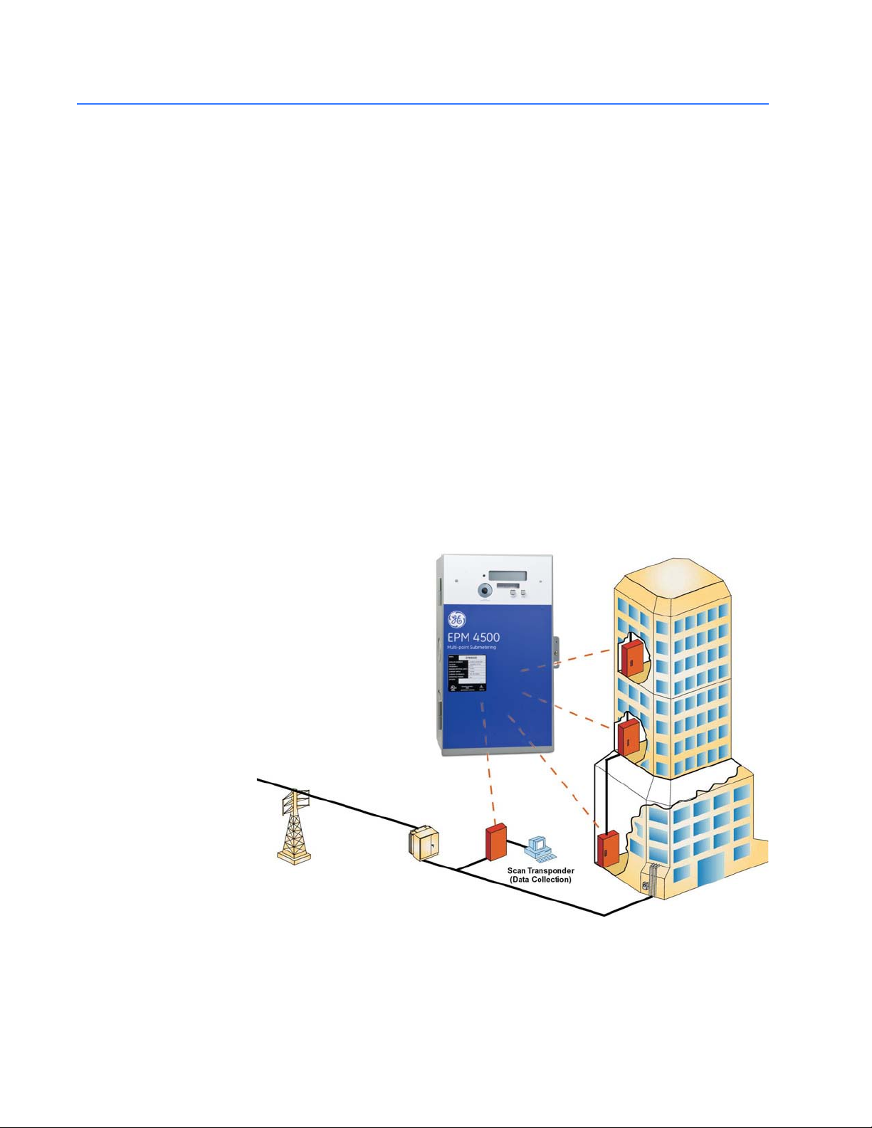
METERING SYSTEM .............................................................................................................. 1-2
INTERIOR VIEW .................................................................................................................... 1-3
CAUTIONS AND WARNINGS ............................................................................................... 1-3
PROTECTIVE CONDUCTOR TERMINAL ............................................................................... 1-4
PREVENTIVE MAINTENANCE ............................................................................................... 1-4
SPECIFICATIONS ............................................................................................................................... 1-5
MONITORING ........................................................................................................................ 1-5
POWER SUPPLY ................................................................................................................... 1-5
METERING ............................................................................................................................. 1-5
INPUTS .................................................................................................................................. 1-6
COMMUNICATIONS .............................................................................................................. 1-6
PHYSICAL .............................................................................................................................. 1-6
TYPE TESTS AND APPROVALS ............................................................................................ 1-6
ORDERING ........................................................................................................................................... 1-8
EPM4500 RESIDENTIAL .................................................................................................... 1-8
EPM4500 COMMERCIAL ................................................................................................... 1-8
OPTIONS ...............................................................................................................................1-8
CURRENT TRANSFORMERS (0.1 A SECONDARY) ............................................................. 1-9
TRANSPONDER MODELS ..................................................................................................... 1-9
PULSE INPUTS ...................................................................................................................... 1-9
2: INSTALLATION GETTING READY ................................................................................................................................ 2-1
DETERMINATION OF METERING SYSTEM REQUIREMENTS .............................................. 2-1
PHASE ASSOCIATION ........................................................................................................... 2-1
WIRING ................................................................................................................................................. 2-2
OVERVIEW OF METER WIRING .......................................................................................... 2-2
WIRING OVERVIEW ............................................................................................................. 2-2
THREE-PHASE FOUR-WIRE WYE WIRING ....................................................................... 2-3
SINGLE-PHASE, THREE-WIRE 120 V WIRING ............................................................... 2-6
THREE-PHASE, THREE-WIRE DELTA WIRING ................................................................. 2-9
SINGLE-PHASE, THREE-WIRE WIRING ............................................................................. 2-12
INSTALLATION OF METER, MCI BOARD, AND CTS ............................................................. 2-15
PROCEDURE .......................................................................................................................... 2-15
INSTALLING THE SCAN TRANSPONDER ................................................................................. 2-18
PROCEDURE .......................................................................................................................... 2-18
3: USING THE METER MENU NAVIGATION ........................................................................................................................ 3-1
USER INTERFACE .................................................................................................................. 3-1
CT MULTIPLIER TABLE .................................................................................................................... 3-4
CT MULTIPLIERS .................................................................................................................. 3-4
VERIFYING METER FUNCTIONALITY ......................................................................................... 3-5
OVERVIEW ............................................................................................................................ 3-5

TOCTOC–II EPM 4500 SUB METER – INSTRUCTION MANUAL
VERIFYING VOLTAGE ........................................................................................................... 3-5
VERIFYING KWHREADING ................................................................................................. 3-5
VERIFYING CURRENT AND ENERGY ................................................................................... 3-6
RESETTING THE DEMAND VALUES ........................................................................................... 3-7
PROCEDURE .......................................................................................................................... 3-7
4: COMMUNICATIONS MODBUS COMMUNICATIONS ..................................................................................................... 4-1
RS485 WIRING FOR MODBUS ......................................................................................... 4-1
RS232 WIRING FOR MODBUS ......................................................................................... 4-2
MODBUS COMMANDS ......................................................................................................... 4-2
FIXED MODBUS VALUES ..................................................................................................... 4-2
MODBUS DATA REGISTER (R4 TYPE) GROUPS ................................................................ 4-3
INSTANTANEOUS DATA ITEMS ............................................................................................ 4-3
32-BIT LONG AND FLOAT DATA FORMATS ..................................................................... 4-4
MODBUS ACTIVATION .................................................................................................................... 4-5
OVERVIEW ............................................................................................................................ 4-5
CONFIGURING ANEW HYPERTERMINAL SESSION .......................................................... 4-5
CONFIRMING CONNECTION TO THE EPM4500 ............................................................. 4-6
LOGGING INTO THE METER ................................................................................................ 4-6
ACTIVATING MODBUS COMMUNICATIONS ....................................................................... 4-7
CHANGING MODBUS SETTINGS ......................................................................................... 4-8
LOGGING OUT ...................................................................................................................... 4-8
DISABLING MODBUS COMMUNICATIONS ......................................................................... 4-8
MODBUS MEMORY MAP ................................................................................................................ 4-9
MEMORY MAP ...................................................................................................................... 4-9
5: MISCELLANEOUS REVISION HISTORY .......................................................................................................................... 5-1
RELEASE DATES ................................................................................................................... 5-1
CHANGES TO THE MANUAL ................................................................................................ 5-2
WARRANTY ......................................................................................................................................... 5-4
GE ENERGY WARRANTY ..................................................................................................... 5-4

EPM 4500 SUB METER – INSTRUCTION MANUAL 1–1
EPM4500 Sub Meter
Chapter 1: Overview
GE Energy
Industrial Solutions
709710A1.CDR
Over view
1.1 Getting Started
1.1.1 Description
Thank you for purchasing the GE Energy EPM4500 24-point sub-meter to monitor energy
for your residential, commercial, or industrial applications. At GE Energy, we pride
ourselves by providing our customers with best-in-class products, which have been
carefully selected by GE to best serve your solution needs.
The EPM4500 is sold in KWh or Demand meter versions and is available for 120/208V and
277/480V applications. An integrated liquid crystal display (LCD) is standard on all versions,
providing local access to real-time and historical data. The meter provides two standard
communication modes: power line communications (PLC), which utilizes existing AC power
lines as the communication medium, eliminating dedicated wiring, and Modbus (RS232,
RS485, and modem).
The EPM4500 is packaged with either solid or split-core CTs in various amperages to suit
both new construction and retrofit applications.
Note The EPM4500 is primarily used for commercial and industrial applications and is
available in voltages ranging from 120 to 600 V in both wye and delta forms. The
following installation instructions are applicable to the EPM4500 meter only.

1–2 EPM 4500 SUB METER – INSTRUCTION MANUAL
APPLICATIONS CHAPTER 1: OVERVIEW
1.2 Applications
1.2.1 Stand-Alone Meter
The GE Energy EPM4500 can be installed as a stand-alone device that is locally accessed
via the LCD or remotely accessed via modem. A modem can be installed in each meter
allowing the meter(s) to be read remotely.
1.2.2 Metering System
The GE Energy EPM4500 family of meters are ideally designed to comprise a metering
system within a residential/commercial building or industrial site. This metering system
can measure electrical usage for each tenant, cost center, or common area space and
communicate this information over the building's power wires or dedicated
communication wiring (RS485). A metering system is comprised of two or more EPM4500
meters and at least one communication transponder (see figure below). The transponder
collects metering data from multiple meters via AC power lines. For larger sites, additional
transponders may be required. Multiple transponders can communicate via a data link
network using RS485 or via a wireless network.
The metering data can be accessed from the transponder or network of transponders
using a telephone modem or local RS232 connection to a PC for data transfers.
FIGURE 1–1: Overview of Scan Transponder Functionality
709712A1.CDR

CHAPTER 1: OVERVIEW APPLICATIONS
EPM 4500 SUB METER – INSTRUCTION MANUAL 1–3
1.2.3 Interior View
The interior of the EPM4500 is shown below.
FIGURE 1–2: Interior View of the EPM4500
Note Where the and symbols are seen on the EPM4500 meter, the manual must be
consulted to determine the nature of any potential hazard and/or actions to be taken.
1.2.4 Cautions and Warnings
• Do not install if the device is damaged. Inspect the housing for obvious defects
such as cracks in the housing.
• If the device is installed or used in a manner not specified by accompanying
documents, the protection of the device may be impaired.
• If the device functions abnormally, proceed with caution. The protection of the
device may be impaired.
• Do not install the meter around combustible gas or gas vapor.
• Do not install the meter in an electrical service with current or voltage outside of
the specified limit of the device.
• Do not operate the meter with the cover removed.
• To avoid electric shock, disconnect mains before replacing fuses!
• See instructions for connection diagram.
• Risk of electric shock. Beware of working around this meter when the voltage is
live.
• For continued protection against fire, replace only with fuses of specified voltage
and current rating.
709711A1.CDR
WARNING
CAUTION

1–4 EPM 4500 SUB METER – INSTRUCTION MANUAL
APPLICATIONS CHAPTER 1: OVERVIEW
1.2.5 Protective Conductor Terminal
Securely fasten one end of the earthing wire so that the screw cuts the paint on the back
box. Securely fasten other end of the wire to a true earth ground connection. When
earthing to the electrical conduit, use continuous pipes, bending when necessary instead
of using couplers.
1.2.6 Preventive Maintenance
There are no necessary preventative maintenance or inspection.
A Toshiba CR2032 coin battery is used in each device and is intended to be good for
decades before replacement. Return to manufacturer for replacement.

CHAPTER 1: OVERVIEW SPECIFICATIONS
EPM 4500 SUB METER – INSTRUCTION MANUAL 1–5
1.3 Specifications
1.3.1 Monitoring
DEMAND
Consumption and demand: .....................kW and kWh
Demand reset: .................................................allows local reset of peak demand register
INTERVAL DATA AND PEAK DEMAND
Commercial:......................................................15 minute block demand interval and peak demand with
date and time stamp
Residential:........................................................1 hour block demand interval
DATA LOGGER
Duration:.............................................................120 days with kW and kWh
Battery:................................................................internal battery maintains time and current interval
metering data during power outage only
1.3.2 Power Supply
CONTROL POWER
Input:....................................................................120 V phase A to neutral
277 V phase A to neutral
480 V phase to phase
(internally powered through metered voltage; no external
source is required)
Frequency:.........................................................50 to 60 Hz
Operating power: ...........................................2 watts for 120 V
5 watts for 277 V and 480 V
Fuses:...................................................................1 - Buss fuse 250 V / 500 V 0.25 A / 0.125 A slow-acting
3 - Buss fuse 250 V /600 V 4.0 A fast-acting
1.3.3 Metering
MEASURED VALUES
Real time per phase:.....................................voltage, current, kW, kvar, kVA, power factor, frequency,
phase angle
Data logging:....................................................kWh, kW demand
METER ACCURACY
Accuracy: ...........................................................0.5 class accuracy
±0.5% unity and 50% power factor, 1 to 100% of full-
scale
Standards: .........................................................meets revenue certifiable ANSI C12.1 and C12.16
accuracy standards
LIQUID CRYSTAL DISPLAY (LCD)
Display size:.......................................................32-digit LCD, 16 digits in two rows
Data digit height:............................................0.31"
Consumption register: .................................6 digits

1–6 EPM 4500 SUB METER – INSTRUCTION MANUAL
SPECIFICATIONS CHAPTER 1: OVERVIEW
1.3.4 Inputs
AC CURRENT INPUTS
CT input:..............................................................50 to 800 A primary available
Secondary inputs: ..........................................0.1 A or 5 A
AC VOLTAGE INPUTS
Metered voltage:.............................................120/208 V wye, 277/480 V wye, or 600 V delta
at 50 to 60 Hz
Rated voltage:..................................................90 to 110%
PULSE INPUTS
Inputs:..................................................................up to 48 form-A pulse inputs logged in programmable
intervals also count during power outage
Minimum wire gauge:...................................20 AWG
Maximum wire length: .................................300 ft.
Maximum rate: ................................................5 transitions/second
Minimum pulse width:..................................100 ms
1.3.5 Communications
EPM4500 COMMUNICATIONS
Protocols:............................................................Power line communications (PLC)
RS485 Modbus (2-wire, half-duplex, isolated)
Ports: ....................................................................IEC front optical point-of-access (POA) port
1.3.6 Physical
ENVIRONMENT
Usage:..................................................................For indoor use only
Enclosure:...........................................................NEMA 1 rated
Temperature:....................................................–20°C to +60°C
Humidity:............................................................0 to 95% relative humidity (non-condensing)
Pollution degree:.............................................1
Maximum altitude:.........................................2000 m
DIMENSIONS
Meter enclosure:.............................................13.5"H ×8.5"W ×4.5"D
CT terminal board enclosure: 13.5"H ×8.5"W ×4.5"D
SHIPPING
Shipping weight: .............................................1 meter assembly 34 lbs. (total weight)
Shipping dimensions: ...................................2 enclosures, each 13.5"H ×8.5"W ×4.5"D
1.3.7 Type Tests and Approvals
TYPE TESTS
Transient/surge suppression: ANSI C37.90.1-1989
Installation category:....................................III. This product falls under Installation Category III
because of its distribution level, fixed installation and has
smaller transient overvoltages than an Installation
Category IV.

CHAPTER 1: OVERVIEW SPECIFICATIONS
EPM 4500 SUB METER – INSTRUCTION MANUAL 1–7
APPROVALS
ANSI: .....................................................................C12.1 and C12.16 accuracy
UL and CUL: ......................................................recognized under E204142
Industry Canada:............................................MC#AE-1148

CHAPTER 1: OVERVIEW
1.4 Ordering
1.4.1 Enclosure
Step 1: Select Enclosure
Family Back Box Voltage Options Description
PL4500 BBA * * Back Box Assembly
120V 120/208V 3 phase, 4 wire
208V 208V 3 phase 3 wire
240V 120/240V, 1 phase, 3 wire
277V 277/480V 3 phase, 4 wire
347V 347/600V 3 phase, 4 wire
480V 480V 3 phase 3 wire
E Future Communications Provision
1.4.2 EPM 4500 Residential
The EPM 4500 residential package is available in single-phase 120/208 V or 120/240 V connections.
Residential use measures kWh only (no demand measurement).
Step 2: Select required meter head
Residential
Family Voltage Phase Wires Application Metering Points CTs Options Description
PL4500 * * * * * * *
120 3 4 R 120/208V 3 phase, 4 wire
03 3 Points
06 6 Points
09 9 Points
12 12 Points
24 24 Points
L 0.1 Amps Secondary Input
H 5 Amps Secondary Input
P Pulse Data Input Module
240 1 3 R 120/240V, 1 phase, 3 wire
12 12 Points
24 24 Points
L 0.1 Amps Secondary Input
H 5 Amps Secondary Input
P Pulse Data Input Module
277 277/480V 3 phase, 4 wire
347 347/600V 3 phase, 4 wire
3 4 R 24 L 24 points, 0.1 secondary CTs
1.4.3 EPM 4500 Commercial 4-Wire
The EPM 4500 commercial package is available in three-phase 120/208 V, 277/480 V, or 347/600 V
connections (delta optional). Commercial use measures kWh and kW demand.
Commercial 4-Wire
Family Voltage Phase Wires Application Metering Points CTs Options Description
PL4500 * * * * * * *
120 120/208V 3 Phase
277 277/480V 3 Phase
347 347/600V 3 Phase
3 4 C 3 Phase 4 wire Commercial
06 6 Points
08 8 Points
L 0.1 Amps Secondary Input
H 5 Amps Secondary Input
P Pulse Data Input Module
M Modem
RS RS485 Connection
MOD Modbus Communication
1–8
ORDERING
EPM 4500 SUB METER – INSTRUCTION MANUAL

2. Order Transponder Model with options
Description Cat. No.
120/208V with modem TRANS120M
120/208V with RS485 and RS2332 connections TRANS120RS
277/480V with modem TRANS277M
277/480V with RS485 and RS232 connections TRANS277RS
347/600V with modem TRANS347M
347/600V with RS485 and RS 232 connections TRANS347RS
1. Order Back Box
Description Cat. No.
120V service back box TRANS BBA 120V
277V service back box TRANS BBA 277V
347V service back box TRANS BBA 347V
EPM 4500 SUB METER – INSTRUCTION MANUAL
ORDERINGCHAPTER 1: OVERVIEW
1–9
1.4.4 EPM 4500 Commercial 3-Wire
Commercial 3-Wire
Family Voltage Phase Wires Application Metering Points CTs Options Description
PL4500 * * * * * * *
208 208V 3 phase 3 wire
480 480V 3 phase 3 wire
3 3 C 12 12 points
L 0.1 Amps Secondary Input
P Pulse Data Module
M Modem
RS RS485 Connection
MOD Modbus Communication
1.4.5 Current Transformers (0.1 A Secondary)
CTs
Type Description Cat. No.
Solid Core - 0.1 A Secondary
CT-50 (50/0.1A) PLSUBCTSL050
CT-1 (100/0.1A) PLSUBCTSL101
CT-2 (200/0.1A) PLSUBCTSL201
CT-4 (400/0.1A) PLSUBCTSL401
Solid Core - Canadian CT-2/5DARL (200A/5A) PLSUBCTSL201CDN
Split Core - 0.1 A Secondary
CTSP-50 (50/0.1A) PLSUBCTSP050
CTSP-1 (100/0.1A) PLSUBCTSP101
CTSP-2 (200/0.1A) PLSUBCTSP201
CTSP-4 (400/0.1A) PLSUBCTSP401
CTSP-8 (800/0.1A) PLSUBCTSP801
CTSP-12 (1200/0.1A) PLSUBCTSP1201
CTSP-20 (2000/0.1A) PLSUBCTSP2001
CTSP-30 (3000/0.1A) PLSUBCTSP3001
CTSP-40 (4000/0.1A) PLSUBCTSP4001
1.4.6 Transponder Models
To order: Select Back Box, then select transponder model with options.
1.4.7 Pulse Inputs
The order codes for the pulse inputs are indicated below.
Cat. No.
PL4500PULSINA
PL4500PULSINB
PL4500PULSINC
PL4500PULSIND
For additional information on pulse inputs, please contact GE Energy.

1–10 EPM 4500 SUB METER – INSTRUCTION MANUAL
ORDERING CHAPTER 1: OVERVIEW

EPM 4500 SUB METER – INSTRUCTION MANUAL 2–1
EPM4500 Sub Meter
Chapter 2: Installation
GE Energy
Industrial Solutions
709710A1.CDR
Instal lation
2.1 Getting Ready
2.1.1 Determination of Metering System Requirements
Determine if the application is for a metering system or for a stand-alone meter. If the
application is for a stand-alone meter, please read Overview of Meter Wiring on page 2–2.
If the application is for a metering system, then also read Installing the Scan Transponder
on page 2–18.
2.1.2 Phase Association
As shown in Table 2–1: Wiring Diagram / Model Reference on page 2–3, there are four
wiring types for the EPM4500 meter. Each wiring type has a specific phase association
table to ensure that current transformers are in-phase with the reference voltage. These
phase association tables must be followed for the meter to function properly with the
chosen wiring type.
The phase association of the current transformers must be followed or meter will not
be installed correctly.

2–2 EPM 4500 SUB METER – INSTRUCTION MANUAL
WIRING CHAPTER 2: INSTALLATION
2.2 Wiring
2.2.1 Overview of Meter Wiring
Although this document treats the installation and certification stages separately, this
does not imply that the recommended procedure is to install the entire system at once and
then proceed to certification.
The recommended procedure is to install and certify the system in stages. By doing this,
systematic error can be corrected before it propagates through the entire installation. To
follow the recommended procedure, divide the job up into manageable stages and install
and certify at each stage before proceeding to the installation of the next stage.
For the purposes of this discussion, the colors black, red and blue have been chosen to
distinguish among the three phases of a three-phase network. White is the designated
color of neutral and green is the color of earth ground. Please substitute the correct color
according to local electrical code. For a two-phase installation, ignore the third phase (the
blue phase in the following description).
Failure to follow the proper procedures and reference the correct wiring diagram can
result in damage to the equipment and/or physical harm.
FIGURE 2–1: Vertical Mounting Option
2.2.2 Wiring Overview
Review the following wiring types and select the one that matches your installation
requirements and part number using the following table.
709714A1.CDR

EPM 4500 SUB METER – INSTRUCTION MANUAL
WIRINGCHAPTER 2: INSTALLATION
2-3
Table 2–1: Wiring Diagram / Model Reference
Section
Three-Phase Four-Wire Wye Wiring on page 2–3
Single-Phase, Three-Wire 120 V Wiring on page 2–6
Three-Phase, Three-Wire Delta Wiring on page 2–9
Single-Phase, Three-Wire Wiring on page 2–12
2.2.3 Three-Phase Four-Wire Wye Wiring
The phase association and polarity of the current transformers must be followed or
the meter will not be correctly installed.
1. Current transformers must be in-phase with the reference voltage. The MCI board
runs in an A-B-C phase rotation (see table below) and each of the three CT
connections repeat an A-B-C order.
For example, a current transformer installed in-phase with reference voltage A must
be installed on CT1, CT4, CT7, etc. Current transformers installed in-phase with
reference voltage B must be installed on CT2, CT5, CT8, etc. Likewise, current
transformers installed in-phase with reference voltage C must be installed on CT3,
CT6, CT9, etc.
2. For the “C” or commercial 3-phase/4-wire model, each A-B-C combination is a single
meter point (see the following table for full listing). That is,
3. – Meter 1 (M#1) is CT1, CT2, and CT3
– Meter 2 (M#2) is CT4, CT5, and CT6
– Repeated for M#3 to M#8
4. After completing all current transformer terminations, connect four (4) current
connectors and then remove the twenty-four (24) shorting links.
5. Follow all local codes for installation requirements; e.g. conduit, fused disconnect,
distance, and wiring.
6. Installation of “L” (0.1 A inputs) and “H” (CL10 or 5A inputs) are the same. For 6 point
models, use meter points M#1 to M#6; M#7 and M#8 are not functional.
If breakers are energized, shorting links must be installed before:
1. disconnecting the CT headers
2. replacing or installing meter heads on the panel.
Bodily injury may result if shorting links are not installed!

2–4 EPM 4500 SUB METER – INSTRUCTION MANUAL
WIRING CHAPTER 2: INSTALLATION
Table 2–2: Phase Association Table for 3-Phase 4-Wire Wye Wiring
Mete
r
MCI Board CT Voltage
Phase
Mete
r
MCI Board CT Voltage
Phase
1
1A
5
13 A
2B 14B
3C 15C
2
4A
6
16 A
5B 17B
6C 18C
3
7A
7
19 A
8B 20B
9C 21C
4
10 A
8
22 A
11 B 23 B
12 C 24 C

CHAPTER 2: INSTALLATION WIRING
EPM 4500 SUB METER – INSTRUCTION MANUAL 2–5
FIGURE 2–2: 3-Phase 4-Wire Wye Wiring
709701A3.CDR
ØAØB ØCIA IB IC
NA NB NC N
120/208V
277/480V
347/600V
Ferrite
Beads
Power Header
MC-5
CT3 CT1
CT4 CT2
MCI INTERFACE
TENANT BREAKER PANEL
Tenant Breaker Panel
Conduit
RECOMMENDED:
Service Disconnect Switch
15A Fast Acting Only
Neutral
Phase A (ØA)
Phase B (ØB)
Phase C (ØC)
BL RD
BK WH
BK
RD
BL
WH
BK
RD
BL
WH
BK RD
BL
WH
To CT1 To CT3
To CT2 To CT4
CT Header CT Header
CT Header CT Header
WH
RD
BL
BK
BK RD BL WH
WH
WH
WH
BL
BK
RD
ØA
ØB
ØC
Shorting Links
WH
BK
WH
RD
WH
BL
WH
BK
WH
RD
WH
BL
WH
BK
WH
RD
WH
BL
WH
BK
WH
RD
WH
BL
WH
BK
WH
RD
WH
BL
WH
BK
WH
RD
WH
BL
WH
BK
WH
RD
WH
BL
WH
BK
WH
RD
WH
BL
Diagram 2. Shorting Links. See
Installation Notes for details.
Meter #1Meter #2Meter #3
Meter #4
Meter #1
Meter #8 Meter #7 Meter #6 Meter #5
Power
Source
Connect CT Header to
meterhead
A
B
C
N
Load
Load
Load
Diagram 3. CT Phasing.
Dot or H1 should point
towards the line or
source.
Reference Voltage
CRITICAL - Current Transformers (CT) must be
installed correctly. See Diagram 1 for CT installation
for each meter point. See Diagram 3 for CT polarity
and Table 1 for Phase Association relationships.
Diagram 1. Current Transformers installed
inside tenant breaker panel.
LINE SOURCE
BK/RD/BL
WHITE
Dot
H1
RD
BK
Meter #2
ØB
ØA
WH
WH
BL
ØC
BL
WH
RD
BK
WH

CHAPTER 2: INSTALLATION
2-6 EPM 4500 SUB METER – INSTRUCTION MANUAL
WIRING
2.2.4 Single-Phase, Three-Wire 120 V Wiring
The phase association and polarity of the current transformers must be followed or
the meter will not be correctly installed.
1. Current transformers must be in-phase with the reference voltage. The MCI board
runs in an A-B-C phase rotation (see table below) and each of the three CT
connections repeat an A-B-C order.
For example, a current transformer installed in-phase with reference voltage A must
be installed on CT1, CT4, CT7, etc. Current transformers installed in-phase with
reference voltage B must be installed on CT2, CT5, CT8, etc. Likewise, current
transformers installed in-phase with reference voltage C must be installed on CT3,
CT6, CT9, etc.
2. For the “R” or residential 3-phase/3-wire model, each A-B, C-A, and B-C combination
is a single meter point (see the table below for full listing). That is,
3. – Meter 1 (M#1) is CT1 and CT2
– Meter 2 (M#2) is CT3 and CT4
– Repeated for M#3 to M#12
4. After completing all current transformer terminations, connect four (4) current
connectors and then remove the twenty-four (24) shorting links.
5. Follow all local codes for installation requirements; e.g. conduit, fused disconnect,
distance, and wiring.
6. Installation of “L” (0.1 A inputs) and “H” (CL10 or 5 A inputs) are the same. For the 3,
6 and 9 point models, use meter points M#1 to M#3, M#1 to M#6, and M#1 to M#9,
respectively. M#4 to M#12, M#7 to M#12, and M#10 to M#12 are not functional for
the 3, 6 and 9 point models, respectively.
If breakers are energized, shorting links must be installed before:
1. disconnecting the CT headers
2. replacing or installing meter heads on the panel.
Bodily injury may result if shorting links are not installed!
Table of contents