GE Lighting Tetra Contour User manual

Tools required:
Components required:
UL approved 18 AWG (0.82mm
2
) supply
wire
End caps
Light guide connectors
Mounting clips
Weather box
22 AWG (0.33mm2) tie-wire
#8 & #10 (M3 or M4) self drilling pan
head screws
#6 (M2) screws
UL approved 22-14 AWG (0.33-2.08mm
2
)
twist-on wire connectors
Tetra 24 Volt Power Supply
Tetra Contour light engine
Tetra Contour light guide
Tools and Components
1
2
3
4
5
6
7
8
* NOTE: xx = color code
9
10
11
12
(GERDXNLE1, GERCXNLE1, GEYAXNLE1, GEGLXNLE1, GEBLXNLE1, GEWHXNLE1, GEWWXNLE1)
Installation Guide
Tetra®Contour
LED Lighting System
GE
Lighting Solutions 24
Volt
imagination at work
)m
4
4
.
2
(
t
e
e
f
8
1 2 4
7 9
5
)m
4
4
.2
(
t
e
e
f
8
3
10
11
12
8
1 2
4
3 5
Wire stripper/cutter
Tape measure
Screwdriver
Electrical grade silicone
Cordless drill
1
2
3
4
5
®
6

Attaching Light Engines
1 Push each 16 in. (406mm) light engine
segment into the clips. Fold loose
wires behind light engines.
2
Install a mounting clip, using #6 (M2)
counter sink screws, every 5–8 inches
(127–203mm) on center until the end
of the run is reached.
5-8 in. (127-203mm)
Electrical grade silicone
31 Push the light engine segments down
into the light guide.
Install a minimum of one clip per 18 in.
(457mm) using #10 (M4) screws.
NOTE: Standard neon hardware can
also be used.
Plan the layout by measuring the design layout and dividing by 8 ft. (2.44m) to
determine the required quantity of Tetra Contour. Refer to the Cutting Resolution Chart
at right when cutting any Tetra Contour section.
NOTE: Do not use more than one suffix code for each respective application, as mixing
suffix codes may result in appearance variation. Suffix code can be found on the
packaging label.
METHOD A - without light guides
If required, cut wire loops between
sections or through light engine in the
appropriate area (refer to the Cutting
Resolution table above).
3
Use twist-on wire connectors to join
cut wires together. Fold wires behind
light engines.
65 CAUTION: Anytime light engine or
supply wire is cut and wire is exposed,
electrical grade silicone must be
applied (see list on the next page for
recommendations).
METHOD B - with light guides
2
Push into clips
If required, cut wire loops between
sections or through light engine (refer
to the Cutting Resolution table above).
NOTE: Installation methods shown are for straight runs. For custom shapes, refer to the Light Guide Forming Instructions.
18 in. (457mm)
Connect two
negatives (–)
Connect four
positives (+)
NOTE: Installation methods shown are for straight runs. For custom shapes, install
mounting clips at regular intervals throughout the shape to provide adequate
support for the light engine.
NOTE: DO NOT bend the light engine to an inside radius that is tighter than 5/8 in.
(16mm). The light engine is not intended for excessive or repetitive bending.
Cutting Resolution Table
4 Separate wires and identify outer
conductors as positive (+) and
middle conductors as negative (–).
Strip ends back 0.5 in. (13mm).
+ +
+ + –
–
Separate wires
CAUTION
Risk of damage. Light engine by itself is intended
for use in dry indoor application only.
Light Engine Color Cutting Resolution
Red 2.67 in. (68mm)
Red-Orange 2.67 in. (68mm)
Amber 2.67 in. (68mm)
Green 2.00 in. (51mm)
Blue 2.00 in. (51mm)
White 2.00 in. (51mm)
Warm White 2.00 in. (51mm)

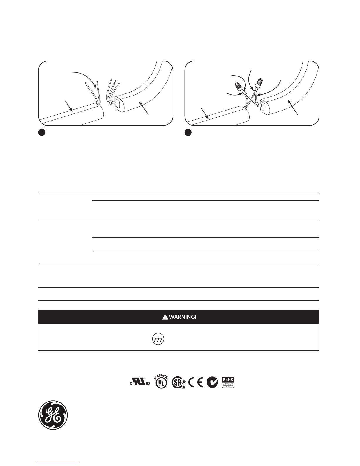
Connect the two outer wires (+) from
the LED strip to the red wire (+) of the
power supply. Connect the middle
wire (-) from the LED strip to the black
wire (-) of the power supply.
NOTE: Grounding and bonding must
be done in accordance with National
Electrical Code (Article 600). See
power supply instructions.
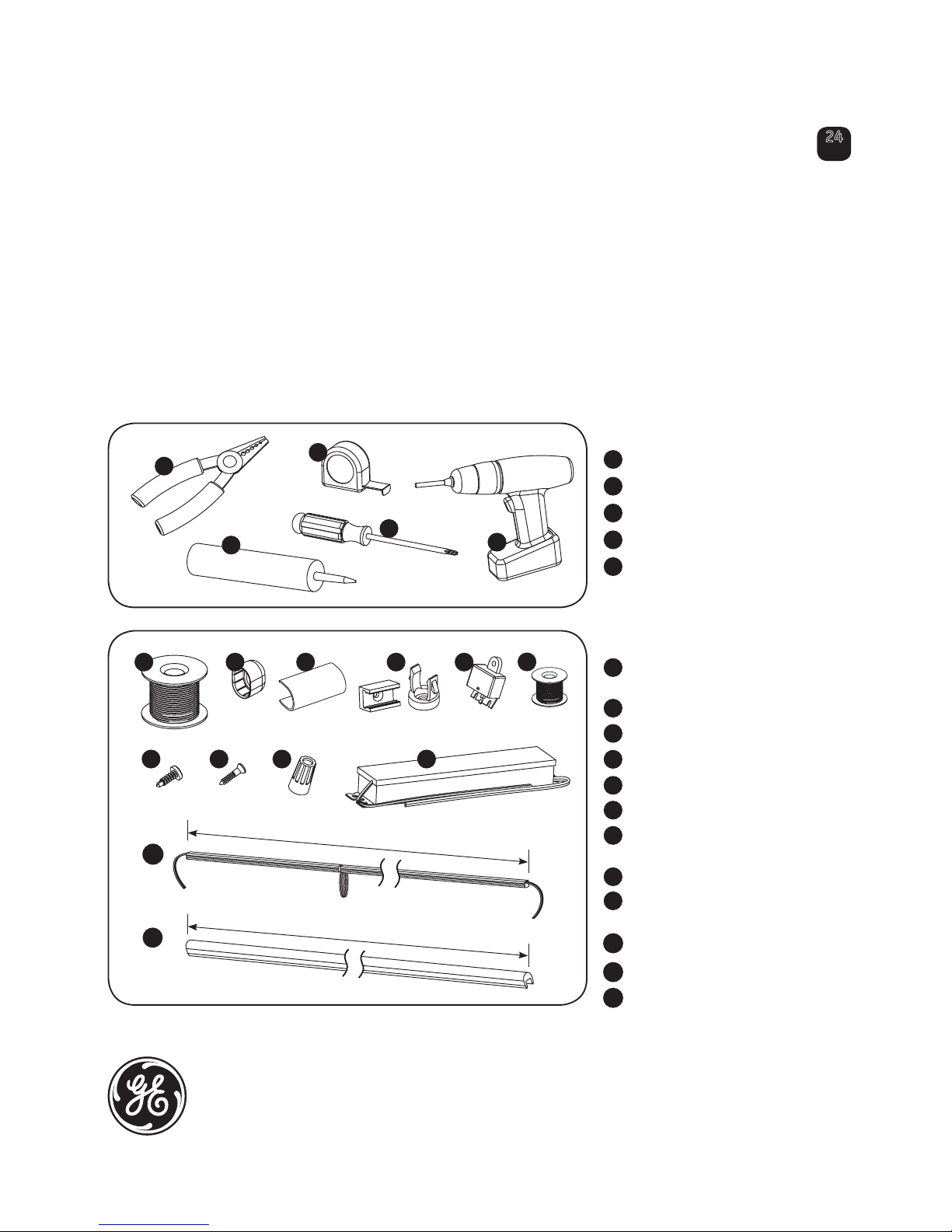
4 Attach Tetra Contour to the mounting
clips, leaving a 3/8 in. (10mm) gap
between sections to allow for expansion
or contraction. Secure light guide by
twisting tie-wire around the mounting
clip and light guide.
8 At any open end, apply electrical
grade silicone and press fit a
GExxLGEC15 light guide end cap to
the Tetra Contour.
9
Electrical grade silicone
At each gap between Tetra Contour
sections, snap on a GExxLGC15 light
guide connector.
3/8in. (10mm)
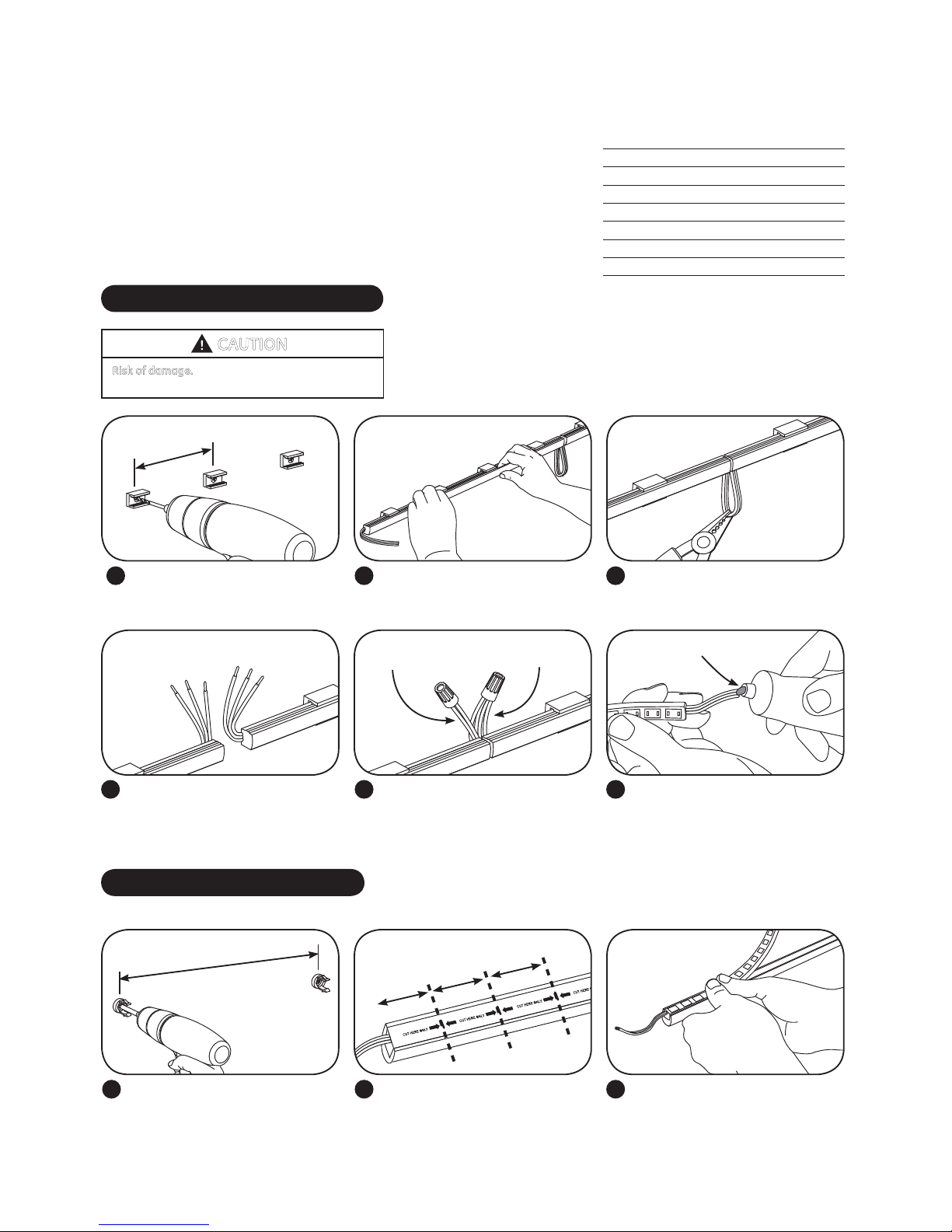
6 Use twist-on wire connectors to join
wires together. Fold wires behind
light engines.
5 Separate wires and identify outer
conductors as positive (+) and
middle conductors as negative (–).
Strip ends back 0.5 in. (13mm).
+ +
+ + –
–
Electrical grade silicone
Connect two
negatives (–)
Connect four
positives (+)
Separate wires
7 Insert wire connectors into weather
box. Fill with electrical grade silicone
and close box. Weather box can be
mounted using #8 (M3) screws.
NOTE: Weather box is required for all
outdoor electrical connections.
Weather box can be painted
Connect Power Supply
Run a wire from the power supply to
a section of Tetra Contour.
NOTE: Power supply connection
must be completed in an acceptable
UL/NEMA enclosure.
NOTE: Power supply loading is
described in the power supply
installation instructions.
Separate wires and identify outer
conductors as positive (+) and middle
conductor as negative (-). Strip ends
back 0.5 in. (13mm).
1 2
WARNING
Risk of electrical shock. Turn power OFF
before inspection, installation or removal.
Example electrical grade silicones include: GE RTV 6700 Series Silicone Rubber Adhesive Sealant, GE White Blanc RTV 162 Silicone
Rubber Adhesive Sealant-Electrical Grade, Dow Corning 3140 - Non-Corrosive Flowable (clear), Dow Corning 3145 - Non-Corrosive
Nonflowable (clear or gray) & Dow Corning RTV 748 Non-Corrosive Sealant-White
+
+
–
Power
supply
To Tetra Contour
Red (+)
Black (-)
3
To power supply
Black (-) Red (+)
Middle wire (-)
Outer wires (+)

ARCH002-R120210
Symptom Condition
All LEDs are OFF
Some LEDs
appear dim
Some of the sections are
not illuminated
Light/dark banding
along a section
Solution
No AC input. Attach AC input and/or check circuit breaker.
Check wire connection(s) at the Tetra Contour LED light engine and
power supply for improper connections or short circuits. Make sure you
have positive to positive and negative to negative wire connections.
Incorrect wire attachment.
Overload (maximum load exceeded). Ensure the overall length of Tetra Contour LED light engine does not
exceed the maximum load as detailed in the Tetra Power Supply
Installation Instructions.
Maximum recommended supply wire
length exceeded.
Reduce the length of supply wire equal to or below the
recommended maximum.
Mixed Suffix Codes of LED light engine
within an application.
Make sure that all LED light engines have the same Suffix Code (Suffix
Code is located on each packaging label).
Incorrect wire attachment. Check the wire connections at the Tetra Contour LED light engine for
improper connections. Make sure you have positive to positive and
negative to negative wire connections. Check for improper cutting
resolution locations (see Method B step 2).
LED light engine stretched during installation. Remove LED light engine and properly install.
Troubleshooting
Conforms to the following standards:
RISK OF ELECTRIC SHOCK:
~Turn power OFF before inspection, installation or removal.
~?roperly ground Tetra Power Supply enclosure.
~BWdc^UU_^wer at fuse box or circuit breaker before installation.
RISK OF FIRE:
~5^[[^fP[[=42P]S[^RP[R^STb.
~DbT^][hD;P__roved wire for input/output connections. Minimum size 18 AWG (0.82mm
2
)
Optional–Attaching Tetra Contour to Tetra Contour LS
2 Splice the white wire with red stripe (+) of Tetra Contour LS
to the two outside wires (+) of Tetra Contour and splice the
white wire (-) of Tetra Contour LS to the center wire (-) of
Tetra Contour. Insert wire connectors into weather box. Fill
with electrical grade silicone and close box.
Tetra Contour LS
Tetra Contour
Outside wires (+)
Center wire (-)
1 Tetra Contour LS can be connected to formable Tetra
Contour for custom shapes. Separate wires and identify
conductors as positive (+) and negative (–). Strip ends back
0.5 in. (13mm).
Tetra Contour LS
+
+ + –
–
Tetra Contour
White wire with
red stripe
White wire with red stripe (+)
White wire (-)
GE Lighting Solutions ~ '''<Y-GE-LED ~fww.gelightingsolutions.com
1 - 8 8 8 - 6 9 - 4 3 - 5 3 3
GE Lighting Solutions is a subsidiary of the General Electric Company. Tetra is a trademark of GE Lighting Solutions. The GE brand and logo are trademarks of the General Electric Company.
© 2011 GE Lighting Solutions. Information provided is subject to change without notice. All values are design or typical values when measured under laboratory conditions.
This device complies with Part 15 of the FCC Rules. Operation is subject to the following two conditions: (1) this device may not cause harmful interference, and (2) this device must accept any interference
received, including interference that may cause undesired operation. This Class [A] RFLD complies with the Canadian standard ICES-005. Ce DEFR de la classe [ A ] est conforme à la NMB-005 du Canada.
This manual suits for next models
7
Table of contents
Popular Landscape Lighting manuals by other brands

Enchanted Garden
Enchanted Garden 343-1786 installation instructions

Essential Garden
Essential Garden 3705MR20 owner's manual

GE
GE StayBright 72232 Assembly instructions

Westinghouse
Westinghouse W-038 owner's manual

AMP Lighting
AMP Lighting AAL-1015-40-B-BZ Installation & maintenance guide

STEINEL
STEINEL Spot Way Sensor Connect instructions

Intermatic
Intermatic Malibu CL501 quick start guide

BSi
BSi iOMNI installation guide

COLORKINETICS
COLORKINETICS Flood MP G2 installation instructions

Delta Light
Delta Light CITYSCAN 525 E14 A installation instructions

Delta Light
Delta Light Tweeter X P 30 manual

HAMPTON BAY
HAMPTON BAY HD22105 instructions