515 BLOCKING AND TEST SYSTEM – INSTRUCTION MANUAL 1
GE
Grid Solutions
Overview
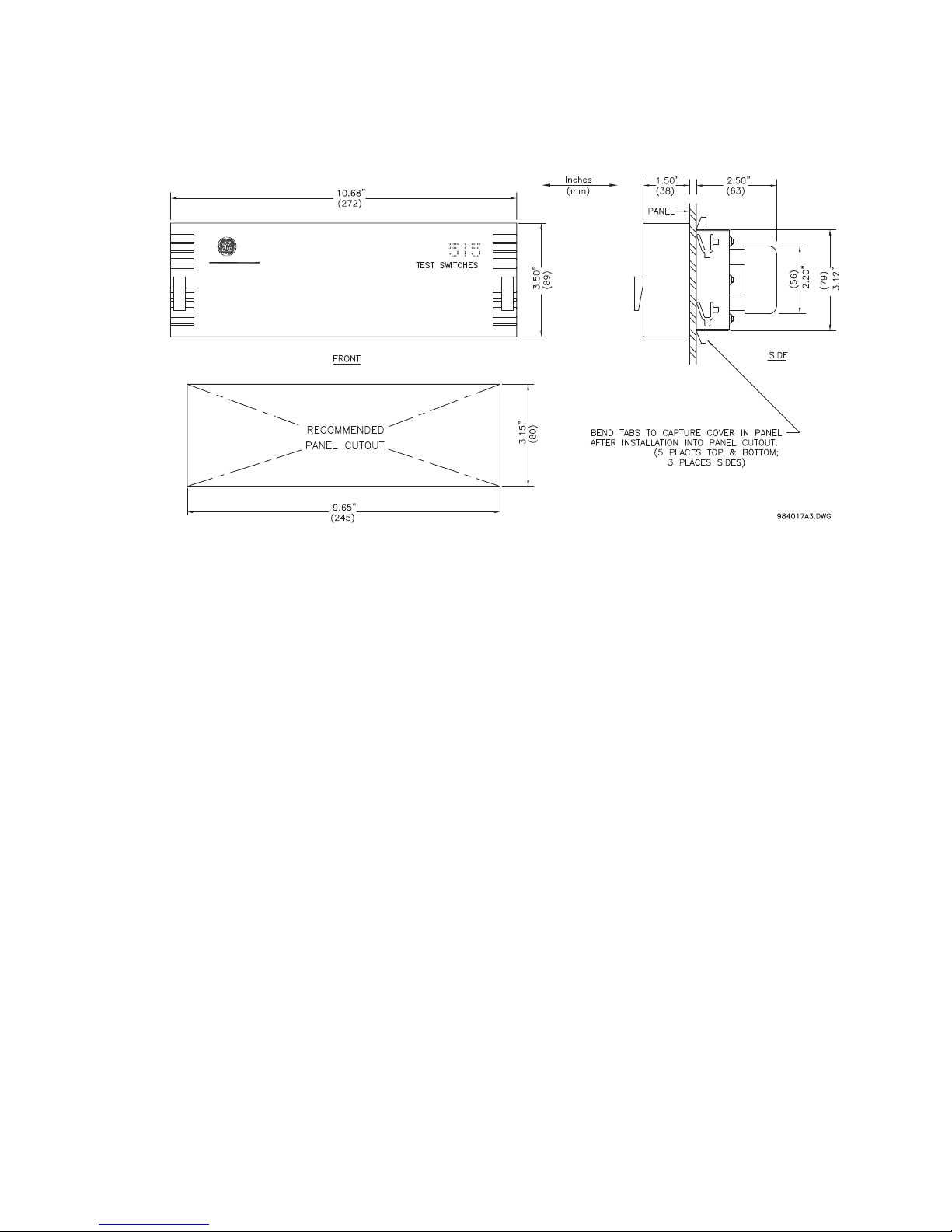
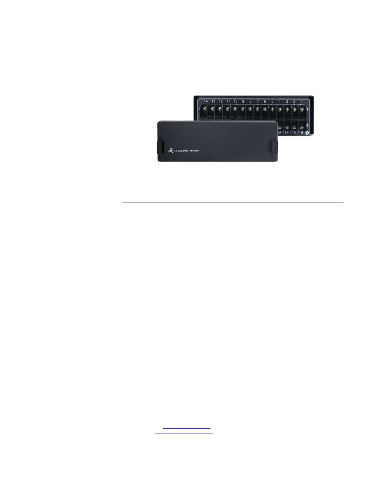
515 Features The GE Multilin 515 Blocking and Test Module has the following features:
• 14 Pole switchbank
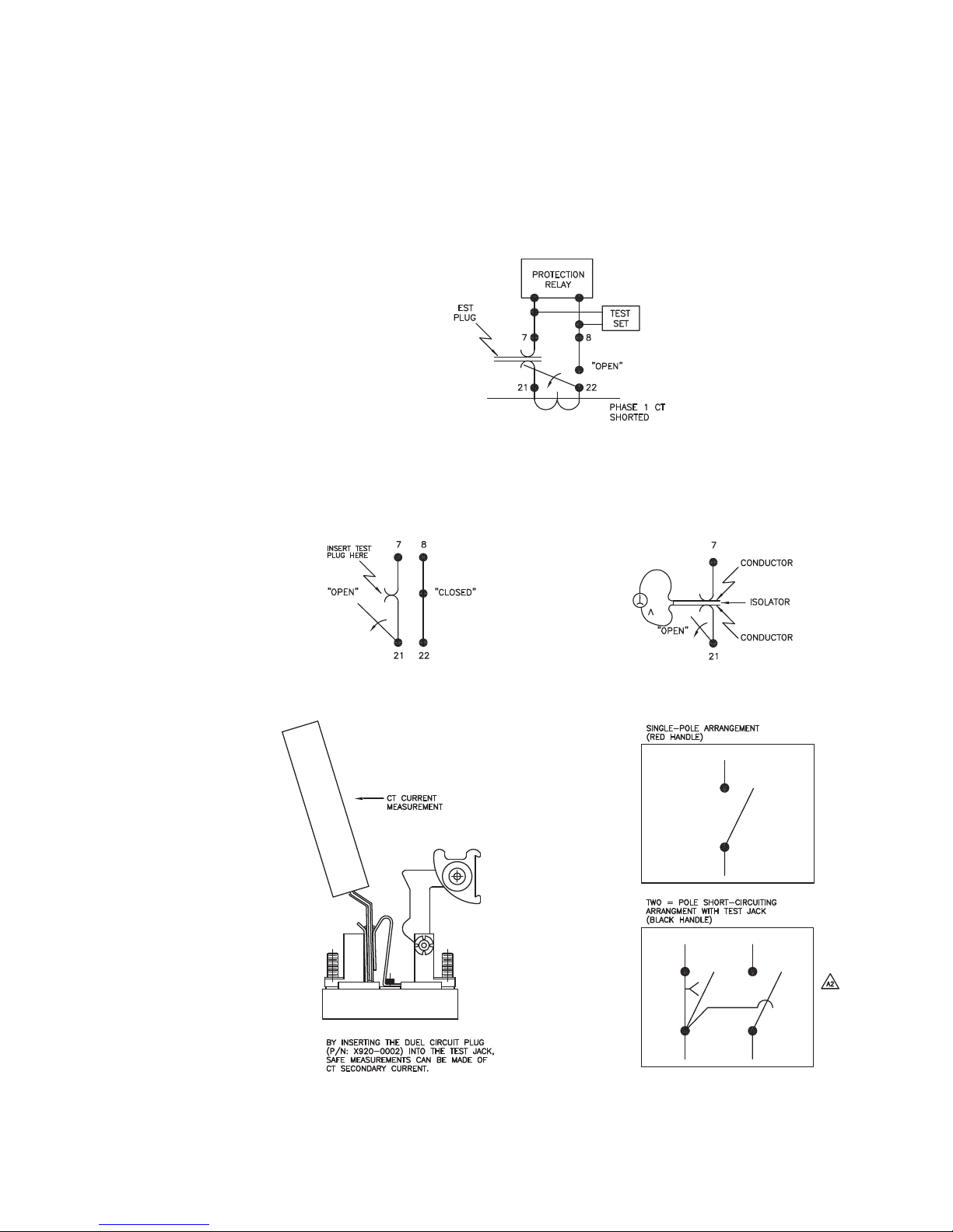
• CT inputs short when current switches are opened
• Current injection for each phase
• Ground terminal
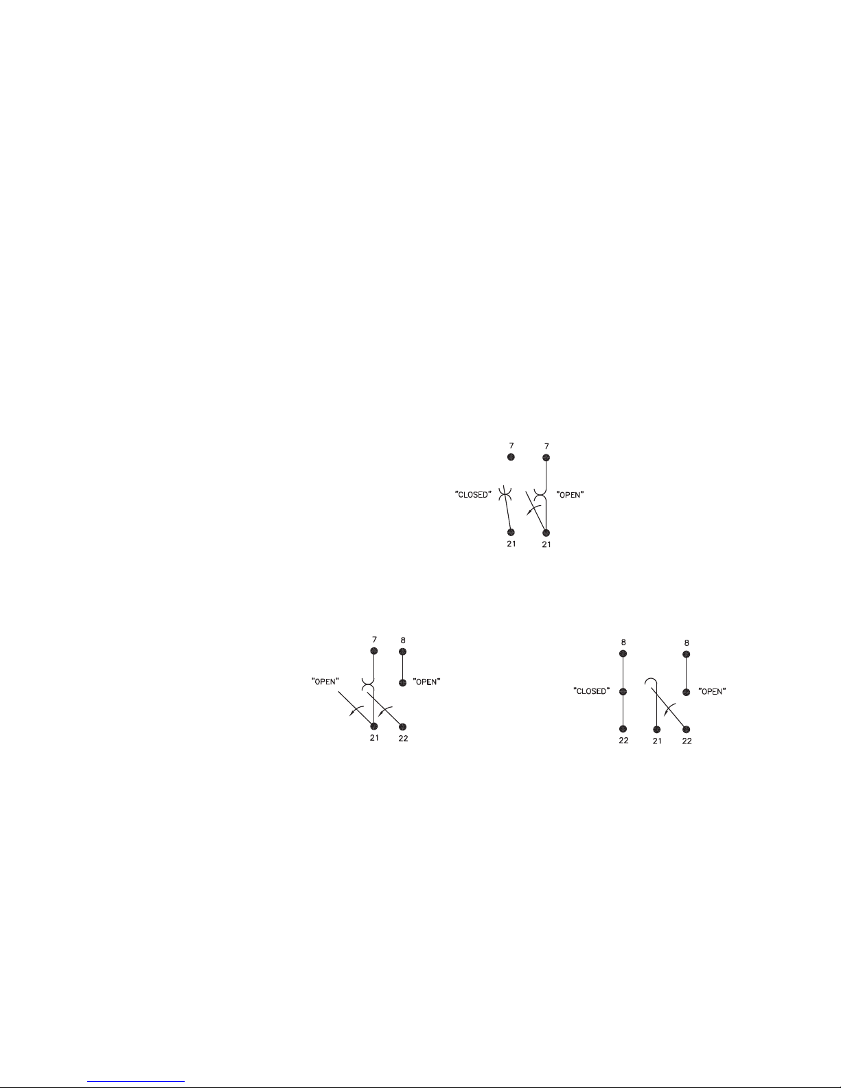
• Ability to visually isolate (open) trip relay output circuits
• Cover provided
• Suitable for utility and industrial use
• 515 test plugs available.
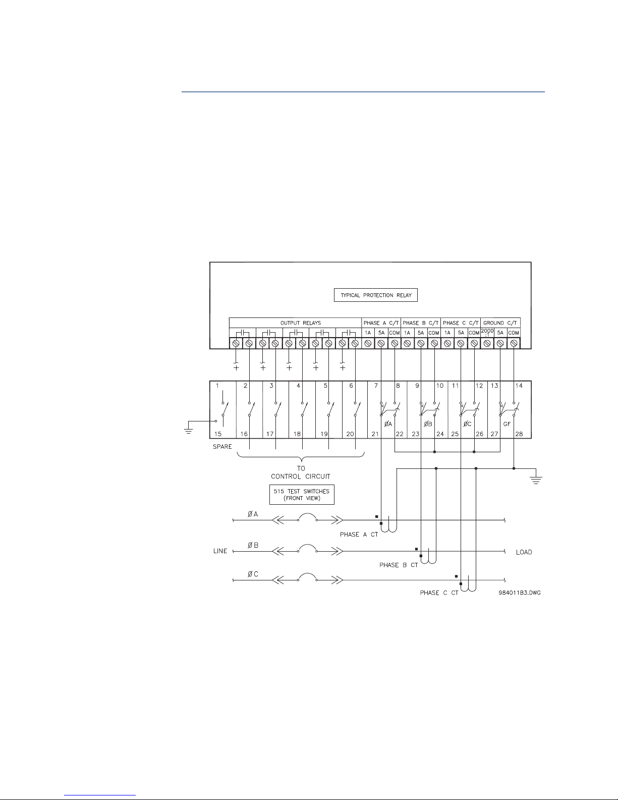
Description The 515 Blocking and Test Module provides an effective means of trip blocking, relay
isolation and testing of GE Multilin relays. By opening the switches and inserting test plugs,
phase and residual currents from the primary CTs can be monitored. Currents can be
injected into the relay from a secondary injection test set during commissioning.
Prior to testing, the trip and auxiliary circuits must first be opened to prevent nuisance
tripping; CTs can then be shorted. Conversely, when the test is complete and the relay put
back into operation, the CT switches should be closed first to ensure normal operation of
the relay, prior to closing the trip and auxiliary circuits.
Further Assistance For product support, contact the information and call center as follows:
GE Grid Solutions Worldwide telephone: +1 905 927 7070
650 Markland Street Europe/Middle East/Africa telephone: +34 94 485 88 54
Markham, Ontario North America toll-free: 1 800 547 8629
Canada L6C 0M1 Fax: +1 905 927 5098
Website: http://www.gegridsolutions.com/multilin
515 Blocking and Test System
Instruction Manual
GE Publication Number: 1601-0024-A6
Copyright © 2017 GE Multilin Inc.