GE JGP989 How to use

C
C
PUB # 31-9080 06/01
MODEL SERIES:
JGP989
TECHNICAL SERVICE GUIDE
GE Consumer Home Services Training
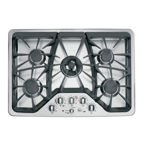
Profile
Gas-on-Glass
Cooktop

IMPORTANT SAFETY NOTICE
The information in this service guide is intended for use by
individuals possessing adequate backgrounds of electrical, elec-
tronic, and mechanical experience. Any attempt to repair a major
appliance may result in personal injury and property damage. The
manufacturer or seller cannot be responsible for the interpretation
of this information, nor can it assume any liability in connection
with its use.
WARNING
If the information in this manual is not followed exactly, a fire or
explosion may result causing property damage, personal injury or
death. If you smell gas:
- Do not try to light any appliance.
- Do not touch any electrical switch; do not use any phone in
the building.
- Immediately call the gas supplier from a neighbor’s phone.
Follow the gas supplier’s instructions.
- If you cannot reach the gas supplier, call the fire department.
WARNING
To avoid personal injury, disconnect power before servicing
this product. If electrical power is required for diagnosis or test
purposes, disconnect the power immediately after performing the
necessary checks.
RECONNECT ALL GROUNDING DEVICES
If grounding wires, screws, straps, clips, nuts, or washers
used to complete a path to ground are removed for service, they
must be returned to their original position and properly fastened.
GE Consumer Home Services Training
Technical Service Guide
Copyright © 2001
All rights reserved. This service guide may not be reproduced in whole or in
part in any form without written permission from the General Electric Company.
!

– 1 –
TableofContents
Table of Contents
Introduction . . . . . . . . . . . . . . . . . . . . . . . . . . . . . . . . . . . 2
Installation . . . . . . . . . . . . . . . . . . . . . . . . . . . . . . . . . . . 3
ConversiontoLP(Propane)Gas . . . . . . . . . . . . . . . . . . . . . . . 4
Specifications and Nomenclature5 . . . . . . . . . . . . . . . . . . . . . . 8
WarrantyInformation . . . . . . . . . . . . . . . . . . . . . . . . . . . . . . 9
Cooktop Features and Controls. . . . . . . . . . . . . . . . . . . . . . . . 10
MechanicalDisassembly . . . . . . . . . . . . . . . . . . . . . . . . . . . . 13
Troubleshooting . . . . . . . . . . . . . . . . . . . . . . . . . . . . . . . . 19
Component andConnectorLocator Views . . . . . . . . . . . . . . . . . . 21
Schematics . . . . . . . . . . . . . . . . . . . . . . . . . . . . . . . . . . . 22
Parts List . . . . . . . . . . . . . . . . . . . . . . . . . . . . . . . . . . . . 24
[[Title]]

– 2 –
Introduction
ThenewProfileGas-on-GlassDowndraftModel
cooktopsmakeaneloquentstatementofstyle,
convenience,andkitchenplanningflexibility.
Whetherchosenforitspurityofdesign,attention
todetail,orbothofthesereasons–you’llfindthese
downdraftgascooktops’superiorblendofform
andfunctionwillbeadelightforyearstocome.
Thesecooktopscontainseveralnewfeatures,
suchasglasscooktopsurfaces,sealedburners,
anda400-CFMdowndraftventingsystem.
Theinformationonthefollowingpageswillhelp
youservicethesecooktopseffectivelyand
efficiently.

– 3 –
Installation
WARNING:Beforebeginningtheinstallation,
switchpoweroffattheservicepanelandlockthe
servicedisconnectingmeans.Whentheservice
disconnectingmeanscannotbelocked,securely
fastenawarningtagtotheservicepanel.
BeforeYouBegin...
Note: The complete installation instructions
areinclosedwiththe
UseandCareManual
.
Carefully read and follow these instructions.
30-in.CooktopDimensions
Dimensionsforreferenceonly.
Unitshownfullyassembled.
Unitmustbeventedtotheoutside!
Never reuse old flexible
connectors. The use
of old flexible connectors
can cause gas leaks
and personal injury.
Always use NEW
flexible connectors
when installing a
gas appliance.
20
5
⁄
8
″
Cutout
20
5
⁄
8
″
Cutout
20
5
⁄
8
″
Cutout
6″Min.
Min.
Electrical
outlet:
12″ above
cabinet
floor
Electrical
outlet:
12″ above
cabinet
floor
Pressure
regulator
Pressure
regulator
Pressure
regulator
Electrical
outlet:
12″ above
cabinet
floor
6″Min.
Shut-off
valve
Shut-off
valve
Shut-off
valve
″Pipe
1
⁄
2
″Pipe
1
⁄
2
″Pipe
Electrical
cord
42″ long
Electrical
cord
42″ long
Electrical
cord
42″ long
Solid Pipe Connection Solid Pipe Connection with Elbow
Union
Elbow
Union
Flexible Connection
GasSupply
Thesecooktopsaredesignedtooperateonnatural
gasat4in.ofwatercolumnpressureoronLPgas
at10in.ofwatercolumnpressure.Forproper
operation,themaximuminletpressuretothe
regulatormustbenomorethan10in.of water
columnpressurefornaturalgasand14in.of
watercolumnpressureforLPgas.
GasSupplyShutoff Valve
Thecooktopitselfisnotequippedwithagasshut-
offvalve.Ifinstalledcorrectly,ashutoffvalvewillbe
inthemaingassupplyline“upstream”ofthe
appliancepressureregulator.
MeasuringtheGasPressure
SuppliedtotheBurners
Connectthetubingsuppliedwithamanometer
overoneendofthemanometer.Removeaburner
capandheadfromtheapplianceandplacethe
otherendofthetubingovertheburnerorifice.Turn
onthegastotheorificeyouaretestingandlightat
leastoneotherburnertoserveasaload.
21
7
⁄
8
″
20
1
⁄
2
″
19″
6″Dia.
29
7
⁄
8
″
6″
28
3
⁄
4
″
6”
1/2

– 4 –
PartsIncluded
PART QUANTITY
Brass orifices 4
Stick-on rating label 1
Installation instructions 1
GasSupply
Withtheinstallationofthisconversionkit,the
cooktopshouldoperateonLPgasat10in.of
watercolumnpressure.
Thepressureregulatormustbeconnectedin
serieswiththemanifoldofthecooktopandmust
remaininserieswiththesupplyline.Forproper
operation,themaximuminletpressuretothe
regulatormustbenomorethan14in.water
columnpressureforLPgas.
Whencheckingtheregulator,theinletpressure
mustbeatleast1in.greaterthantheregulator
outputsetting.Iftheregulatorissetfor10in.of
watercolumnpressure,theinletpressuremustbe
atleast11in.
Note:Disconnectthecooktopandtheindividual
shutoffvalvefromthegassupplypipingsystem
duringanypressuretestingofthatsystemattest
pressuresgreaterthan1/2psig.Isolatethe
cooktopfromthegassupplypipingsystemby
closingtheindividualmanualshutoffvalvetothe
cooktopduringanypressuretestingofthegas
supplypipingsystemattestpressuresequaltoor
greaterthan1/2psig.
ConversiontoLP(Propane)Gas
Note:Beforeyou begin, readthese
instructions completely and carefully.
Thecooktopisfactorysetfornaturalgas
operation.To useLP(propane)gas,theregulator
andburnerorificesmustbeconverted.TheLP
orificespudsforthecooktopburnerscanbe
locatedwithintheliteraturepackageshippedwith
theunit.
IfyouconverttoLPgas,keepinstructionsand
naturalgasorificestoconvertbackforusewith
naturalgas.
Productfailureduetoimproperinstallationisnot
coveredundertheGEAppliancesWarranty.
WARNING:IfyouareusingLP(propane)gas,all
adjustmentsdescribedinthefollowingstepsmust
bemadebeforeattemptingburneradjustmentsor
usingthecooktop.
WARNING: Thisconversionkitshallbeinstalled
byaqualifiedserviceagencyinaccordancewith
themanufacturer’sinstructionsandallapplicable
codesandrequirementsoftheauthorityhaving
jurisdiction.Iftheinformationintheseinstructions
is notfollowedexactly, afire,explosion,or
productionofcarbonmonoxidemayresult,
causingpropertydamage,personalinjury, or loss
oflife.Thequalifiedserviceagencyisresponsible
fortheproperinstallationofthiskit.Theinstallation
isnotproperandcompleteuntiltheoperationof
theconvertedapplianceischeckedasspecifiedin
themanufacturer’sinstructionssuppliedwiththe
kit.
ToolsYouWillNeed
Adjustable wrench 9/32″(7 mm) Nutdriver T15 Torx driver
Small, thin-blade flat screwdriver with approximately 1/8″
blade width is needed to access the calibration screw.

– 5 –
L
L
84
84
L
L
71
99
LP (Propane) Gas 10″W.C.P.
Burner Output Rating in BTU/HR
Location BTUs Orifice Size
LF, LR 8,500 0.84 Lmm
RR 5,500 0.71 Lmm
RF 11,000 0.99 Lmm
Front
Caution:Whenattachingtheburnerbasetothe
glasstopunit,tightento12in./lbsmaxtorque.
Overtighteningwillcausedamage.
4.Replacethegaskets,burnerbases,and
electrodes.Installthe2screwsineachburner
base.Donotovertighten.Themaximumtorque
is10in./lbs.Pushtheignitersallthewaydown
intotheburnerhead.
5.Installtheburnerheads,burnercaps,and
gratesintheiroriginalburnerpositions.
ConvertthePressureRegulator
1.Locatethepressureregulatorundertherearof
thecooktop.
Pressure
regulator
2.Removethenutfromthepressureregulator
withanadjustablewrench.
Natural gas
LP gas
Nut
TurnOFFGasandElectricSupply
Beforeyoubegin,turnOFFthegassupplyatthe
shut-offvalve.Disconnecttheelectricalsupply
fromthecooktop.
Shut-off valve
Electrical supply
ConvertSurface Burners
1.Firstremove,convert,andreplacetheleft-side
surfaceburnersandthentheright-sidesurface
burners.Removethegrates,burnercaps,and
burnerheads.Removethescrewssecuringthe
burnerbasestotheburners.Pulloutthe
electrodeswithoutremovingtheelectrodeleads.
Grate
Brass
locator foot
Burner cap
Electrode
Burner base
Burner head
Burner
base
screw (2)
2.Removethebrassorificespudinthechimney
ofeachburnerusinga9/32-in.(7mm)nutdriver.
Note:TheLPorificesareshorterthanthenatural
gasorifices.
3.InstalltheLPorificespudsintheircorrect
positionsbynumber.
Note:Foroperationatelevationsabove5000 ft.(1500 m),
equipmentratingsshall bereducedat arateof 2%foreach
1000ft.(300m)above sealevelbefore selecting
appropriatelysizedequipment,i.e.,usesmallerorifices.

– 6 –
3.Removetheplasticpinfromtheinsideofthe
nut,turnthepin180degreesandsnapthepin
backintothenut.
Natural gas LP gas
Nut
4.Reinstallthenutontotheregulator.
5.ApplytheLPconversionlabelnexttotherating
plate.
TestforLeaks
WARNING:Donot useaflametocheckforleaks!
Donot usethecooktopuntilallconnectionshave
beenleaktested.
Performleaktestperthefollowinginstructions:
1.Purchasealiquidleakdetectororpreparea
soapsolutionofonepartwater,onepartliquid
detergent.
2.Whenallconnectionshavebeenmade,make
sureallcooktopcontrolsareturnedtoOFFand
turnthegassupplyvalvetoON.
3.Applytheliquidleakdetectororthesoapsolu-
tionaroundallconnectionsfromtheshutoff
valvetothecooktop.
4.Aleakisidentifiedbyaflowofbubblesfromthe
areaoftheleak.
5.Ifaleakisdetected,turnthegassupplyoff.
Tightenthefitting.TurnthegasONandtest
again.Iftheleakpersists,turnthegassupply
OFFandcontactyourdealerforassistance.
Donot attempttooperatethecooktopifaleak
ispresent.
Check Ignition
1.Connectelectricalsupplycord.
2.Pushdownonecontrolknobandturntothe
LITEposition.Theigniterwillsparkandthe
burnerwilllight.Thefirsttestmayrequiresome
timewhileairisflushedoutofthegasline.
3.Checktodetermineifyourburnerflamesare
normal.IfburnerflameslooklikeA,callfor
service.Normalburnerflamesshouldlooklike
BorC,dependingonthetypeofgasyouuse.
WithLPgas,someyellowtippingonouter
conesisnormal.
A–Yellow flames
Call for service
B–Yellow tips
Normal for
LP gas
C–Soft blue flames
Normal for
natural gas
4.TurntheknobtoOFF.
5.Repeattheprocedureforeachburner.
AdjustingLowFlame(Simmer)Setting
WARNING: Thefollowingadjustmentsmustbe
madebeforeturningontheburner.Failuretodoso
couldresultinseriousinjury.Besurepressure
regulatorhasbeenconverted.
Note:Thetopburnervalveshavelowflame/
simmeradjustmentscrewsinthecenterofthe
controlshafts.Aflashlightmaybeneededto
locatethescrew. Asmallthin-bladescrewdriver
(approximately1/8-in.bladewidth)isneededto
accessthe screw.
1. Light2otherburnersandsettheknobstoa
MEDIUMtoHIsetting.
2. Lighttheburnertobeadjustedandturnthe
knobtoLOW.
3. Removetheknobandinsertascrewdriverinto
thevalveshaft.
4. Turntheadjustmentscrewuntiltheflame

– 7 –
reachesthedesiredsize.
5. Performaflamestabilitytestwiththedowndraft
fanonHIGH.
FlameAdjustments
Note:Theburnersdonothaveairshuttersadjust-
mentsandusenonadjustableorifices.Ifthe
flameliftsofftheburner,orifyouexperience
yellow-tippedflamesand/orsootintheflames,
besuretocheckthefollowing:
1. Gaspressure:4-in.W.C.P.(natural)and10-in.
W.C.P.(LP).
2. Inspectorificetobesureitisdrilledinthe
centerandfreeofdebrisorburrs.
3. Besurethecorrectsizeorificeisintheproper
location.
4. Makesurethecooktopwasproperlyconverted
ifonLP.
5. Ifthecauseofsootingcannotbefoundinthe
abovechecks,replacetheorificewithone
havingasmallerdiameteropening.
TestingFlameStability
1. WiththedowndraftventfanonHI,turnthe
burnerknobfromHItoLOWquickly.Ifthe LOW
flamegoesout,increasetheflamesizeand
testagain.
2. WiththeburnerontheLOWsetting,openand
closethecabinetdoorunderthecooktop.Ifthe
flameisextinguishedbytheaircurrentscre-
atedbythedoormovement,increasetheflame
heightandtestagain.
FlameRecheck
Aftertheadjustmentismade,turnallburnersOFF.
Igniteeachburnerindividually.Observetheflame
attheHIposition.RotatethevalvetotheLOW
positionandbesuretheflamesizedecreasesas
thevalveisrotatedcounterclockwise.
Note:Oncetheconversioniscompleteand
checkedOK,fillouttheLPstickerandinclude
yourname,organization,anddateconversionwas
made.Applythestickernearthecooktopgasinlet
openingtoalertothersinthefuturethatthis
appliancehasbeenconvertedtoLP.Ifconverting
backtonaturalgasfromLP,pleaseremovethe
stickersoothersknowtheapplianceissettouse
naturalgas.
ConvertingBacktoNaturalGas
ReversetheprocedureforconvertingtoLP,
locatingtheorificesasfollows:
N
N
150
150
N
N
122
169
Front
Natural Gas 4″W.C.P.
Burner Output Rating in BTU/HR
Location BTUs Orifice Size
LF, LR 9,100 1.50 Nmm
RR 5,500 1.22 Nmm
RF 11,500 1.69 Nmm
Note:Foroperationatelevationsabove5000ft.
(1500m),equipmentratingsshallbereducedata
rateof2%foreach1000ft.(300m)abovesea
levelbeforeselectingaproximatelysized
equipment,ie.,usesmallerorifices.

– 8 –
Specifications and Nomenclature
ModelNumber
SerialNumber
Thefirsttwocharactersoftheserialnumber
identifythemonthandyearofmanufacture.
Example: AA123456S=January,2001
A-JAN 2005-H
D - FEB 2004-G
F-MAR 2003-F
G -APR 2002-D
H-MAY 2001-A
L-JUN 2000-Z
M-JUL 1999-V
R -AUG 1998-T
S - SEP 1997-S
T - OCT 1996-R
V-NOV 1995-M
Z- DEC 1994-L
Theletterdesignatingthe
yearrepeatsevery12
years.
Example:
T-1974
T-1986
T-1998
J G P 9 8 9 B C B B
Product
J=GECookingProduct
Features
G=Gas
Configuration
P=Cooktop FeaturePack
Designatesfeatures–thehigher
thenumber,themorefeatures.
Color
BB=BlackonBlack
WW=Whiteon White
CC=BisqueonBisque
YearModelCreated
C=2000
ColorFamily
B=Black
T = TrueWhite
K = TrueBisque
Theserialplateofyourcooktopislocatedon
thebottomoftheburnerbox.Inadditionto
themodelandserialnumbers,ittellsyouthe
ratingsoftheburnersandthetypeoffuel
andpressurethecooktopwasadjustedfor
whenitleftthefactory.
ForburnerBTUrateandorificesize,refertothe
ConversiontoLP(Propane)Gas
chapter.
Thedowndraftventingsystemblowerisratedat400CFM.

– 9 –
Warranty Information
Warrantor:GeneralElectricCompany,Louisville,KY 40225
■Service trips to your home to teach you how to use
the product.
■Improper installation.
■Failure of the product if it is abused, misused, or used
for other than the intended purpose or used
commercially.
■Damage to the glass cooktop caused by the use of
cleaners other than the recommended cleaning creams.
■Damage to the glass cooktop caused by hardened
spills of sugary materials or melted plastic that are
not cleaned according to the directions in the
Owner’s Manual.
■Replacement of house fuses or resetting of circuit
breakers.
■Damage to the product caused by accident, fire, floods
or acts of God.
■Incidental or consequential damage caused by possible
defects with this appliance.
What GE Will Not Cover:
This warranty is extended to the original purchaser and any succeeding owner for products purchased for
home use within the USA. In Alaska, the warranty excludes the cost of shipping or service calls to your home.
Some states do not allow the exclusion or limitation of incidental or consequential damages. This warranty
gives you specific legal rights, and you may also have other rights which vary from state to state. To know
what your legal rights are, consult your local or state consumer affairs office or your state’s Attorney General.
For The Period Of: GE Will Replace:
One Year Any part
of the cooktop which fails due to a defect in materials or workmanship.
From the date of the
During this
full one-year warranty,
GE will also provide,
free of charge,
all labor
original purchase
and in-home service to replace the defective part.
Five Years A replacement glass cooktop
if it should crack or discolor.
From the date of the
During this
limited additional four-year warranty,
you will be responsible for any labor
original purchase
or in-home service to replace the defective part.
Salessliporcancelledcheckisrequiredasproofoforiginalpurchasedateto
obtain service under warranty.
AllwarrantyserviceisprovidedbyourFactoryServiceCentersoranauthorizedCustomer
Care®technician.

– 10 –
CooktopFeaturesand Controls
Throughoutthismanual,featuresandappearancesmayvaryfromthecustomer’smodel.
1
43
97
6
5
2
8
4
79
Feature Index
1. VentGrille
2. VentGrilleGasket
3. VentFilter(locatedundertheventgrille)
4. SimmerSpillproofBurner
5. SpillproofBurners
6. High-PowerSpillproofBurner
7. VentControl
8. SurfaceBurnerControl
9. GlassCooktopSurface
10. Cast-IronBurnerGrates
10 1098 8
7
6
45
5
123

– 11 –
IgnitionSystem
Thesurfaceburnersarelitbyelectricignition,
eliminatingtheneedforstandingpilotlightswith
constantlyburningflames.
Theignitionsystemconsistsof4spark
switches(1oneachvalve),4sparkelectrodes
(1oneachburner),andasparkmodule.
WARNING:All4electrodeswillsparkwhenany
burnercontrolknobisintheLITEposition.
Theburnercontrolknobmustbeturnedtothe
LITEpositiontolighttheburnerandoutofthe
LITEpositiontostopthesparkingafterthe
burnerhasbeenlit.
LightingaBurner
Pushthecontrolknobdownandturnit
counterclockwisetotheLITEposition.
Push the control knob in and turn it
to the LITE position.
Aftertheburnerlights,turntheknobtoadjust
theflametothedesiredsize.Toturnaburner
off,turntheknobclockwiseasfarasitwillgo,
totheOFFposition.
Incaseofapowerfailure,youcanlightthe
burnerswithamatch.Holdalitmatchtothe
burner, thenpushinandturnthecontrolknobto
theLITEposition.Useextremecautionwhen
lightingburnersthisway.Burnersinusewhen
anelectricalpowerfailureoccurswillcontinue
tooperatenormally.
Caution: Donotoperateaburnerforan
extendedperiodoftimewithoutcookwareon
thegrate.Thefinishonthegratemaychip
withoutcookwaretoabsorbtheheat.
SealedGasBurners
Therightrearburnerwillgivethebestsimmer
results.Theotherburnersarebestforgeneral
cookingandfastboiling.
SelectingFlameSize
WARNING:Forsafehandlingofcookware,never
lettheflameextendupthesidesofthecookware.
GEA00262
Watchtheflame,nottheknob,asyoureducethe
heat.Theflamesizeonagasburnershould
matchthecookwareyouareusing.Anyflame
largerthanthebottomofthecookwareiswasted
andonlyservestoheatthehandle.
Selecting Cookware
Aluminum:Medium-weightcookwareis
recommendedbecauseitheatsquicklyand
evenly. Mostfoodsbrownevenlyinanaluminum
skillet.Usesaucepanswithtight-fittinglidsfor
cookingwithminimumamountsofwater.
CastIron:Ifheatedslowly,mostskilletswillgive
satisfactoryresults.
Enamelware:Undersomeconditions,theenamel
ofsomecookwaremaymelt.Followcookware
manufacturer’srecommendationsforcooking
methods.
Glass:Therearetwotypesofglasscookware:
thoseforovenuseonlyandthoseforsurface
cooking(saucepans,coffeepots,andteapots).
Glassconductsheatveryslowly.
Heat-ProofGlassCeramic:Thiscanbeusedfor
eithersurfaceorovencooking.Itconductsheat
veryslowlyandcoolsveryslowly.Checkthe
cookwaremanufacturer’s directionstobesureit
canbeusedongascooktops.
StainlessSteel:Thismetalalonehaspoor
heatingpropertiesandisusuallycombinedwith
copper, aluminum,orothermetalsforimproved
heatdistribution.Combinationmetalskillets
generallyworksatisfactorilyiftheyareusedat
mediumheatasthemanufacturerrecommends.
Push the control knob down and
turn it to the LITE position.

– 12 –
TheWokHolderfitsontopofthecooktopgrateto
providesupportandproperaircirculationfor
traditionalround-bottomedwoksonly. Do not use
flat-bottomedwokswiththeWokHolder.
Recommended
WARNING:Donotusewoksthathavesupport
rings.Placingtheringovertheburnergratemay
causetheburnertoworkimproperly,resultingin
carbonmonoxidelevelsaboveallowablecurrent
standards.Thiscouldbeahealthhazard.Donot
trytousesuchwokswithouttheringunlessyou
areusingtheWokHolder.Seriousburnsmay
resultifthewokistippedover.
UsingStovetopGrills
WARNING:Donotusestovetopgrillsonyour
sealedgasburners.Usingthestovetopgrillon
thesealedgasburnerwillcauseincomplete
combustionandcanresultinexposuretocarbon
monoxidelevelsaboveallowablecurrent
standards.Thiscanbehazardoustothe
customer’s health.
HowtoOperatetheVentSystem
Tooperatethedowndraftventsystem,turnthe
ventfanspeedcontrolknobtoHI,MED,orLOW,
asneeded.
OFF
MED
HI
LO
GEA00186
Using Woks
Werecommendusingonlyaflat-bottomedwok,
availableatlocalretailstores,orusetheWok
Holderaccessorywithtraditionalround-bottomed
woks.TheWokHolderaccessorycanbe
orderedfromyourappliancedealer.
Not recommended
GEA00263

– 13 –
Table of Contents
Igniter Removal. . . . . . . . . . . . . . . . . . . . . . . . . . . . . . . . . . 14
Burner andTopRemoval . . . . . . . . . . . . . . . . . . . . . . . . . . . . 14
Jet Holder Removal . . . . . . . . . . . . . . . . . . . . . . . . . . . . . . . 14
Spark Module Removal . . . . . . . . . . . . . . . . . . . . . . . . . . . . . 15
Igniter Switch Removal . . . . . . . . . . . . . . . . . . . . . . . . . . . . . 15
ValveRemoval . . . . . . . . . . . . . . . . . . . . . . . . . . . . . . . . . . 16
Manifold Removal . . . . . . . . . . . . . . . . . . . . . . . . . . . . . . . . 16
Brace Removal . . . . . . . . . . . . . . . . . . . . . . . . . . . . . . . . . . 17
BlowerAssemblyReplacement . . . . . . . . . . . . . . . . . . . . . . . . . 17
Capacitor Replacement . . . . . . . . . . . . . . . . . . . . . . . . . . . . . 18
Mechanical Disassembly

– 14 –
BurnerandTopRemoval
Note:Thecooktopdoesnotneedtoberemoved
fromthecountertop.
1. Removealligniters(see
IgniterRemoval
).
Torx
Screw Igniter
2. Remove2Torx(T15)screwsfromeachburner
baseandremovetheburnerbases.
Caution:Whenreplacingburnerbaseson
glasstopmodels,donot overtightenscrews
(12 in./lbs.torque).
3. Removetheknobsfromthecooktop.
Caution: Liftthecooktopbytheglasssideedges.
Donot liftfromtheventopening.
4. Liftoffthecooktopandplaceitonaflat,pro-
tectedsurface.
Caution:Graphitegasketsareveryfragile.Care
mustbegiventoavoidbreaking.
5.Removethegraphitegasketsandsetaside.
Note:Whenreassembling,replacethetopbefore
replacingthegraphitegasketstoavoiddamageto
thegaskets.
JetHolderRemoval
1. Removetheburnersandtop(seeBurnerand
TopRemoval).
GEA00773
Graphite GasketGraphite Gasket
Jet HolderJet Holder
Igniter
Wire
Igniter
Wire
RetainerRetainer Burner Support
Burner Support
Burner Support
2. Removethegraphitegasketring.
3. Compressthelegsoftheburnersupportandlift
uptoremove.
WARNING:Disconnectelectricalpowertothe
cooktopandturnOFFgasatthemainvalvebefore
performinganyremovalprocedures.
Note:Thecooktopitselfisnotequippedwithagas
shutoffvalve.Ifinstalledcorrectly, a shutoffvalve
willbeinthemaingassupplyline“upstream”of
theappliancepressureregulator.
IgniterRemoval
1. Removetheburnergrate,burnercap,and
burnerheadfromthecooktop.Remove2Torx
screws(T15)fromtheburnerbase.
Grate Burner cap
Electrode
Burner base
Burner head
Burner base screw (2)
Brass
locator foot
2. Insertaflatscrewdriverbladebetweentheedge
oftheigniterandburnerbase.Pullontheigniter
whileliftingwiththescrewdriver.
Caution:Whenremovingthewirefromtheigniter,
makesureyoudonotdamagetheheatshrink
insulationonthewire.Ifdamaged,repairthewire
insulationwithfiberglasstape.
3. Unplugthewirefromthebaseoftheigniter.
Note:Whenassembling,checktheintegrityofthe
heatshrinkontheigniterleadsgoingtothe
electrodes.Ifdamaged,properignitionmaynot
occur.Repairthewireinsulationwithfiberglass
tape.
Igniter

– 15 –
GEA00774
1/4-in. Screw
1/4-in. Screw
1/4-in. Screw
1/2-in. Nut
1/2-in. Nut
1/2-in. Nut
4. Removethe1/2-in.nutonthegaslinetothejet
holder.
5. Remove2screws(1/4-in.)andtheigniterwire
fromthejetholder.
Note:Wheninstalling,besuretheigniterwireis
placedthroughtheholewiththeretainerclip.
SparkModuleRemoval
Note:ServicingtheSparkModulefromthebottom
saveswearontheignitorcircuitandisstrongly
recommended.
1. Fromunderthecounter,supporttheblower
assemblyandductwork.
2. Removefour7/16-in.nuts(A)frominsidethe
plenumtoseparatetheblowerassemblyfrom
theplenum.
GEA01176
A
3. Fromunderthecounter,removetheright
bottomaccesscoverandremovethehold-
downbracketsfromtheburnerbox.
4. Placeprotectivematerialonthecountertop,lift
thecooktopoutofthecutout,andplaceitatan
angleontheprotectivecovering.
Spark Module
Bracket Screws
5. Removethebottom2screwssecuringthe
sparkmodulebracketfromtherightfrontside
oftheburnerbox(seepreviousillustration).
6. Fromunderthecounter,notepositionsand
unplugthewirestothesparkmodule.
7. Removethe1/4-in.screwandthespark
modulefromthemountingbracket.
8. Installthenewsparkmoduleusingthesame
screws.Replacethecooktopandblower
assemblyinthereverseoftheaboveorder.
IgniterSwitchRemoval
1. Removetheburnersandtop(see
Burnerand
Top Removal
).
2. Unplugthewirestotheigniterswitch(brown
wirefromthesparkmoduleandtheyellowwire
fromtheblowerswitch).
Note:Notethecolorandpositionoftheigniter
switches.
3. Lifteachigniterswitchoffthevalvestem.
Note:Whenreplacingtheswitch,replacethe
entireharnesswithcolorsinsamepositions.The
bottomoftheswitchismoldedtoconformtothe
topofthevalveforalocked-infit.

– 16 –
ValveRemoval
1. Removetheburnersandtop(see
Burnerand
Top Removal
).
2. Lifttheigniterswitchesoffthevalvestems.
(Notethecolorandpositionsoftheswitches.)
3. Removethe1/2-in.nutonthegaslinetothe
valveandremovethegasline.
4. Fromunderthecounter,remove7screws
(1/4-in.)fromthepanelunderthevalves.
5. Removethe1/4-in.screwfromthebottomof
themanifoldandremovethevalve.
ManifoldRemoval
1. Removetheburnersandtop(see
Burnerand
TopRemoval
).
2. Lifttheigniterswitchesoffthevalvestems.
(Notethecolorandpositionsoftheswitches.)
3. Removethe1/2-in.nuts(4)onthegaslinesto
thevalvesandremovethegaslines.
4. Removethegasfittinglocatedunderthe
counterfromthemanifold.
5. Fromunderthecounter,remove9screws(1/4-
in.)fromthe2panelsunderthevalves.

– 17 –
6. Removethe1/4-in.screws(4)fromthemani-
foldmountingbracketsandremovethemani-
foldfromtheburnerbox.
7. Removethe1/4-in.screws(4)fromthemani-
foldandremovethevalves.
BraceRemoval
1. Removetheburnersandtop(see
Burnerand
TopRemoval
).
2. Removetheburnersupports(see
JetHolder
Removal
).
3. Fromunderthecounter,supporttheblower
assemblyandductwork.
4. Removefour7/16-in.nutsfrominsidethe
plenumtoseparatetheblowerassemblyfrom
theplenum.
5. Remove2hold-downbracketsfromunderthe
countertop,lifttheburnerboxfromthecounter,
turnit10degrees,andinsertcardboardor
woodundertheburnerboxtoprotectthe
countertop.
GEA01153
6. Removethe1/4-in.bracescrews(4)fromthe
exterioroftheburnerboxandremovethe
brace.
BlowerAssemblyReplacement
(WB26X10072)
Note:Blowerassemblycanberemovedfromthe
cooktopwithoutremovingthecooktopfromthe
countertop.
Note:Theblowerisathree-speed,tappedwinding
designwithapermanentrun/startcapacitor.
1. Remove2screwsfromtheaccesswiringcover
locatedbelowthecontrolsandunplugthe
blowermotorconnector.
Screws
Screw
(on other side)
GEA00232
2. Disconnectthetransitionductfromtheblower
assembly.
3. Removetheventgrille,ventgrillegasket,and
filter.
GEA01176
A
4. Supporttheblowerassemblyandremovethe
7/16-in.nuts(A)insidetheintakeplenum.
Partsavailable:Completeblowerassemblywith
capacitororreplacementcapacitorWB27X10363.
BraceScrews

– 18 –
CapacitorReplacement (WB27X10363)
WARNING: Disconnecttheelectricalpower
supplybeforeservicingthecapacitor. The
capacitoriscapableofstoringvoltagethatcould
belethal. Donottouchthebareconnector
terminals.
1. Removetheguardsurroundingthecapacitor
shell. Somemodelshaveaflatplasticspacer
betweenthecapacitorshellandthemotor.
Retaintheguardandthespacerforreassem-
bly.
GEA00319
2. Firmlypushupwardonthecapacitorshellto
removethecapacitorfrommotorbracketcap.
GEA00320
WARNING: Makesurethestoredelectrical
chargehasbeendissipatedbyplacinga100-ohm,
2-wattresistoracrosstheterminals,orbyplacing
ascrewdriverbladebetweentheterminalsand
groundingthescrewdrivertothecooktopfor
severalseconds.
GEA00321
Terminals
Terminals
Terminals
3. Carefullydischargebothcapacitorwireharness
terminalsasdescribedabove.
Note: Recordwireharnessconnections.
4. Disconnectterminalsusingneedlenosepliers
andreconnectinsameorientationonnew
capacitor.
5. Firmlysnapnewcapacitorshellcasinginto
motorbracketcap.
6. Replaceplasticspacer(ifsoequipped)and
guardaroundcapacitor.
Other manuals for JGP989
3
This manual suits for next models
1
Table of contents
Other GE Cooktop manuals
Popular Cooktop manuals by other brands

hestan
hestan KEC 30 installation manual

Heartland Appliances
Heartland Appliances Heartland Induction Cooktop Installation and user manual

Omega
Omega OCC64KZTGG instruction manual

Whirlpool
Whirlpool W5CE1522FB01 installation instructions

Thermador
Thermador CIT151DS installation instructions

Lumme
Lumme LU-3637 user manual

Capital
Capital PSCT484BG installation guide

Fisher & Paykel
Fisher & Paykel CE302 Series Installation instructions and user guide

CombiSteel
CombiSteel 7478,0515 instruction manual

Wolf
Wolf SRT364C Specifications

Mr. Induction
Mr. Induction SR-650C instruction manual

KitchenAid
KitchenAid KGCP462 Use & care guide