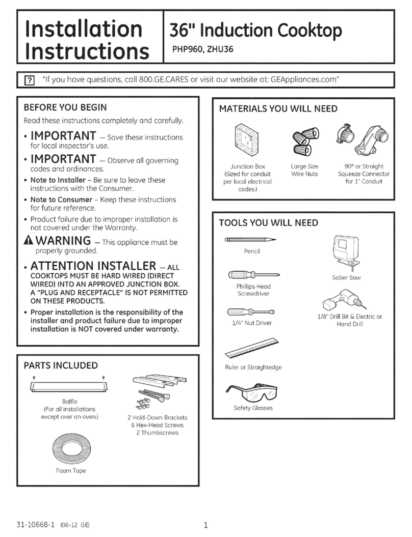
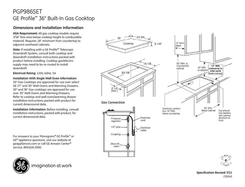
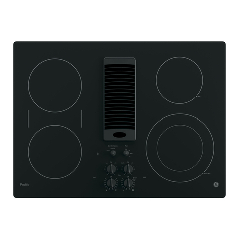
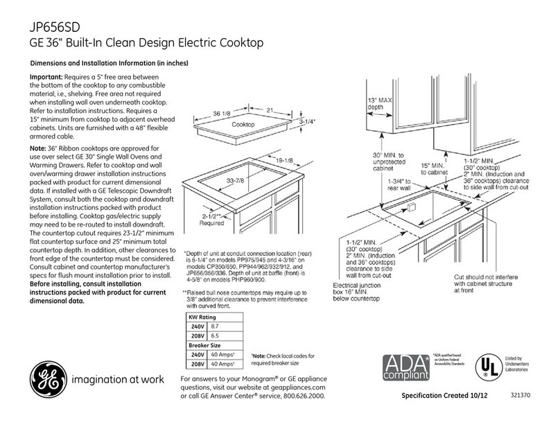
GE Monogram ZEU30R User manual

GE Monogram ®
Installation
Instructions
30" Electric
Radiant Cooktop
Model
ZEU30R
Monograin.coin

gefi)rewmbegin--ReadtheseinstHictionscompletelyandcarefllllv.
IMPORTANT--Saxetheseinstructionsforlocalinspector'suse,
IMPORTANT--OBSERVEALLGOVERNINGCODESANDORDINANCES,
NotetoInstaJler--gesuretoleavetheseinstructionswiththe(hmsumer.
Note to Consumer--Kee I) these inst_ uctions fin" flmu'e reference,
Note--This appliance must be properly grounded.
ATTENTION INSTALLER: ALL COOKTOPS MUST BE HARD WIRED (DIRECT WIRED) INTO
AN APPROVED JUNCTION BOX, A "PLUG AND RECEPTACLE" IS NOT PERMITTED ON
THESE PRODUCTS.
This appliance must be properly grotmded. See "Electrical Connections," page 7.
If you have questions concerning the installation
of this product, call the GE Answer Center _'_
Consumer Inflmnation Service at 800.626.2000,
24 hours a da 5 7 days a week or visit ore" website
at: Monograil/,COIll,
If you received a damaged cooktop, you should
contact vo/Ir dealer.
I
Proper installation is the responsibility of the
installer. Product failure due to improper installation
is not covered under the GE Appliance _hrrantv. See
the Owner's Manual for warranty intormation.
For Monogram local service in your area,
1.800.444.1845.
For Monogram Service in Canada,
1.888.880.3030.
For Monogram Parts and Accessories,
call 1.800.626.2002.
FOR YOUR SAFETY:
For Personal Safer), remove house fuse or open
circuit breaker before beginning installation.
Failure to do so could restdt in serious it_juI')
or death.
Be sure your cooktop is installed properl) b) a
qualified installer or service technician.
To eliminate tile risk of burns or fire b) reaching
over heated surfime elements, cabinet storage
located above the sm'f_me traits should be axoided.
If cabinet storage space is to be provided, the risk
can be reduced b) installing a range hood that
projects horizontall_ a minimmn of 5" beyond tile
bottom of the cabinets. Cabinet installation above
tile cooktop ma) be no deeper than 13".
• Make sm'e tile cabinets and _dl coverings arotmd tile
cooktop can withstand the temperatures (ut) to 200°F)
generated b) the cooktop.
• Tile cooktop shouM be eas) to reach and lighted with
natural light dm'ing the day.
• Always discomlect the electrical service to the cooktop
before repairing or servicing the cooktop. This can be
done b) discomlecting the fuse or circuit breaker:
Failm'e to do this cotdd result in a dangerous or fatal
shock. Know where )ore" main disconnect switch is
located. If )ou do not know, hme your electrician
show }OIA,
Check local building codes fin" the proper method
of cooktop installation, i,ocal codes vary. Installation,
electrical connections and grotmding must comply
with applicable codes.
2
Electrical Requirements
This appliance must be supplied with tile proper voltage and fl'equency, and c(mnected to an
individual, properl) grotmded branch circuit, promcted b) a circuit breaker or a time delay fl_se as noted
on the rating plate.
_,\_ recommend you have tile electrical wiring and hookup of your cooktop c(mnected by a qualified
electrician. After installation, have the electrician show )ou _d_ere yore" main range disc(mnect
is located.
Wiring must contbrm to the National Electrical Code. Y)u can get a cop} of the National Electrical Code,
ANSI/NFPA No. 70-Latest Edition, b) _Titing:
National Fire Protection Associatkm
Batter}march Park
QIIJI1c}_ MA 02269
Tile cooktop conduit wiring is approved ti)r copper wire ccmnection onl) and if you have almninum house
wiring, )ou must use special UL approved comlectors tbrjoining copper to aluminmn.
You must use a two-wire, three conductor 208/240VAC, 60 Hertz electrical system. A white (neutral) wire
is not needed ti)r this trait. The cooktop must be installed in a circuit that does not exceed 125 VAC nominal
to grotmd. Refer to the rating plate on yore" cooktop fin" the KW rating ti)r yore" cooktop.
Contents
Design Information
Electronic Radiant Cooktop
Desigql Information
Models A_ ailable ..................................................................................................................................................................... 3
Adwm_ e Plamling ................................................................................................................................................................... 3
Tools & Materials Required ................................................................................................................................................... 4
Preparhlg the Opelfing
Minimmn Clearances ............................................................................................................................................................. 4
Overall Cooktop Dimensions ................................................................................................................................................. 4
X_'rtical Clearance .................................................................................................................................................................. 5
Cutout Dimensions ................................................................................................................................................................. 5
Wall Coverings, Comuertop & Cabinets ............................................................................................................................... 5
Installation
InstallingJm_ction Box ........................................................................................................................................................... 5
Protectillg the Sur/_tce of the Cookto l) ................................................................................................................................. .5
Aua(h Foam Stril)s ................................................................................................................................................................. 6
I.ocate Momuing Parts .......................................................................................................................................................... 6
Auach Brackets to Cooktop .................................................................................................................................................. 6
Insert the Cooktop into C/ltollt ............................................................................................................................................. 6
Auach the HoM Down Bracket ............................................................................................................................................. 6
Electrical Comlections ........................................................................................................................................................... 7
Checking Installation & Cooktop ()perations ...................................................................................................................... 8
Models ZEU:40R
Available Electronic Radiant Cooktop
Advance
Planning The electrical power to the l
cooktop supply line must be shut J
off while cmmections are being
made. Failure to do so could
result in serious injury or death.
When preparing cooktop opening, make sure
the inside of the cabinet and the cooktop do
not interfere with each other. (See section on
preparing the opening.)
Remox eI)a ckagim*,_ materials and literature
I)ackage, from the cooktoI ) before beginning, ,
installation.
Literature Package
Styrofoam
Packag
Cooktop
Remove Installation Insti uctions fl'om literature pack and
read them careflflly betore you begin.
Be sm'e to place all literatm'e, Owner's Manual, Installation
Instructions, etc. in a sati _place fin" fllture reterence.
_:_,g....
Make sm'e xou haxe all the tools and materials you need
before starting the installation of the eooktop.
Yore" home must proxide the adequate electrical serxice
needed to safely and properly use yore" cooktop. (Reter to
section on electrical requirements.)
X_hen installing, yore', cooktoi ) in xour, home, make sm'e all
local codes and ordinances are followed exactly as stated.
Make sm'e the wall coxerings, cotmtertop and cabinets
arotmd the cooktop can withstand heat (up to 200°F)
generated by the cooktop.

Preparing tile Opening
Electronic Radiant Cooktop
Tools &
Materials
Required
Materials Needed
,]m_ction Box _ire Nuts
Tools You Will Need
1/8" Drill Bit &
Electric or Hand
Drill
Phillips Head
Screwdrher
Ruler t)r
Straightedge Saber Saw
\Pencil
Minimum
Clearances The following MINIMUM clearance
dimensions i///ist be maintained.
13" MAX. Depth
of unprotected _
overhead cabinets
30" MIN.
clearance from
11/2" MIN.
clearance from
/cutout to side
_wail on the right
of the unit
18" MIN.
/height from
countertop to
nearest cabinet on
either side of unit
Overall
k
Coo top
Dimensions
m,
'1
3 1/4"
,m
Ir
hi°7
_51/2"_1
4

Installation
Electronic Radiant Cooktop
Vertical
Clearance Fixe inches (5") mininmn_ xertical clearance between
tile cooktop bottom and am combustible surfitces.
5"Min.
Verlical Clearance
Cutout
Diinensions
of the
Countertop
To insure accuracy, it is best to make a
template when cutting the opening in the
cotmter. Make sm'e there is clearance
inside the cabinet before cutting the
CO/Ul [ei'tol).
1 314"
Between cutout
rear edge and the
wall behind the cooktop
2" MIn. from
front edge of cutout
and front edge of countertop
19 518" width of cut
Wall
Coverings,
Countertop
& Cabinets
Make sure tile wall coxerings,, ctmntertoi ) and
cabinets artmnd tile cooktop can withstand heat
(up t(t 200°F) generated by tile cooktop.
countertop must I
withstand heat up I
to 200°E_
Installing
the
Junction
Box
Install an ai)provedjm_ction box where it
can be easily reached through the front of
the cabinet where the cooktop will be
located. The cooktop conduit is 3 feet long.
IMPORTANT: Thejunction box |
must be located where it will allow I
considerable slack in the conduit |
for serviceability. )
Install junction box
;o that it can be reached
through the front of
the cabinet.
Protect
Surface of
k
Coo top
Place a towel or tablecloth onto tile
com_tertop, i,ay the cookto I) upside down
onto the protected surfitce,
_jBottom of cooktop
Cloth under Cooktop
(Contimmd on following page) 5

Installation
Electronic Radiant Cooktop
Attach
Foam Strips Apply the foam strips around the outer edge
of the glass. Do not overlap the foam strips,
Bottom of
Cooktop
@Foam Strips _ ./
I,ocate
Mounting
Parts
Remoxe the hold down brackets and
screws fl'om the literature )ackaoe
I & "
MOUNTING
SCREW
Attach
Brackets to
k
Coo top
Screw the Hold Down Bracket to the side of
the cooktop trait. Repeat fi_r opposite side
of cooktop. Pre-drilled
Bottom of hole
Cooktop
Insertk
Coo top
Into
Cutout
Insert the cooktop centered into the
cutout opening. Make sure the fl'ont
edge of the c(mutertop is parallel to
the cooktop. Make final check that all
required clearances are met.
w
IMPORTANT: If the cooktop
is being installed into a blind
comlter (one with no cabinet
opening below), wire connections
must be made before putting the cooktop
into the cutout opening.
H°ld n
Bracke_
<75><Z>
Attach
Hold Down
Brackets to
Cabinet
Open the cabinet door and screw the Hold
Down Brackets to the cabinet sides with the
screws proxided.

Electrical Connections
Electronic Radiant Cooktop
Step 1X_q/en makin,*_ tile wire connections, use tile entire length, of conduit proxided. The conduit must not be
shortened.
Step 2X4qth the cooktop in place, open the front of the cabinet door.
Step 3 Insert tile wires from tile conduit through tile oi)enim,
of thejtmction box.
Ground.._ Clamp
Step 4Connect tile red and black leads from tile
cooktop conduit to tile corresi)onding, leads
in thejm_ction box. ou 2
wire
location
Step Ouce tile couuectious aye I/lade, sec/IFe wires
together using wire UtltS.
Red
/_Strain
_l_Relief
L_ Clamp
Ground/',,1_'Black
GROUNDING INSTRUCTIONS
The bare ground wire in the conduit is cmmected to the cooktop frame. Effective Jmmary 1, 1996, the
National Electrical Code will not permit grounding through neutral If used in new construction after
January 1, 1996 or in a mobile home, recreational vehicle or if local codes do not permit grounding
through the neutral white lead, attach the appliance grounding lead (green or copper) to the residence
grounding conductor (green or bare copper) in accordance with local codes. When cmmecting to a 3
conductor branch circuit, if local codes permit, connect the bare ground cmmector lead of the cooktop to
the branch circuit neutral (gray or white in color).
IMPORTANT: If the cooktop is being installed into a blind counter (one with no cabinet opening below),
wire cmmections must be made before putting the cooktop into the cutout opening.
NOTE: ALUMINUM WIRING
A. WARNING:
IMPROPER CONNECTION OF ALUMINUM HOUSE WIRING TO THE COPPER LI_M)S CAN
RESULT IN A SERIOUS PROBLEM.
B. Spfice copper wires to aluminum wiring using special cmmectors designed mad UL approved for joi_fing
copper to aluminum and follow the manufacturer's recommended connector procedure closely.
NOTE: Wire used, location mid enclosure of splices, etc., must conform to good wiring practice and
local codes. 7

Checking tile Installation & Cooktop Operation
Electronic Radiant Cooktop
Pre-Test
Checklist • Relnove all protective fihn if l)i'esellt, and anv stickers.
• Check to be sure that all wiring is secure and not pinched or in contact with moving parts.
• Checklevel of appliance.
• Check that the cooktop is propedy grounded.
Operation
Checklist • Remove all items fl'om the top of the cooktop surface.
• Turn on the power to the cooktop. (Refer to wmr Owner's Manual.) Verilk' that all surtace traits
operate properly.
• Check that the circuit breaker is not tripped nor the house fllse blown.
• Check that conduit is securely connected to the junction box.
• See Owner's Manual fin" troubleshooting list.
• NOTE TO ELECTRICIAN:
The power leads supplied with this appliance are UL recognized for commotions to larger gauge
household wiring. The insulation of these leads is rated at temperatures much higher than the
temperature rating of household wiring. The current carryhlg capacity of a conductor is governed
by the wire gauge and also the temperature rating of the insulation around the wire.
Monogram ®
(;eneral Electric Company
I,ouisxille, KY 40225
7
NOTE: X_,hik performing installations
described in this book, saf(ty glasses or goggle s
should b¢ worn.
'Ib obtain specific information concerning any
Monogram product or serxice, call GE Answer
Centel-_consumer intormation service at
800.626.2000--any time, day or night or xisit our
DT_l)sit(' at: *_[OII()_I-HIII,('OI_I,
For Monogram lo(al sevvice in your m-ca,call
1.800.444.1845.
NOTE: Product improvement is a continuing
endeaw)r at General Electric. Th_ reibre,
mat_ rials, appearance and specifications are
sul_ject to change without notice. 31-10a43
229c4053P527
(09/02,1R)
Other manuals for Monogram ZEU30R
4
Other GE Cooktop manuals

GE
GE PGP989 Original instructions

GE
GE Profile PVP6004 User manual

GE
GE PVM9179, PSA9120, PSA9240 User manual

GE
GE Profile PP945 User manual

GE
GE JP655SMSS User manual

GE
GE JP939 User manual

GE
GE Monogram ZGU385N User manual

GE
GE Monogram ZEU30R User manual

GE
GE Monogram ZGU36GG User manual

GE
GE Profile PGP990DEN Installation instructions