manuals.online logo
Brands
  1. Home
  2. •
  3. Brands
  4. •
  5. GE
  6. •
  7. Cooktop
  8. •
  9. GE 36 ELECTRIC RADIANT COOKTOP ZEU36R Operating and installation instructions

GE 36 ELECTRIC RADIANT COOKTOP ZEU36R Operating and installation instructions

36” RADIANT COOKTOP WITH ELECTRONIC CONTROLS
GROUNDING SPECIFICATIONS
Ground Path Resistance 0.10 :Max.
Insulation Resistance 250 K:Min.
INSTALLATION REQUIREMENTS
Power Supply
The cooktop must be connected to a supply circuit of the proper
voltage and frequency as specified on the rating plate. Wire size
must conform to the National Electrical Code or the prevailing local
code. The rating plate is located on the side of the component box.
WIRING
Built-in power leads are UL-approved for connection to larger
gauge household wiring. The insulation of these leads is rated
at temperatures much higher than the temperature rating of
household wiring. The current-carrying capacity of a conductor is
governed by the temperature rating of the insulation around the
wire rather than the wire gauge alone.
WARNING: IMPROPER CONNECTION OF ALUMINUM
HOUSE WIRING TO THESE COPPER LEADS CAN RESULT IN
A SERIOUS PROBLEM. USE ONLY CONNECTORS DESIGNED
FOR JOINING COPPER TO ALUMINUM AND FOLLOW THE
MANUFACTURER’S RECOMMENDED PROCEDURE CLOSELY.
CERAMIC GLASS COOKTOP
If the glass is damaged it must be replaced in combination with
the touch board; these two components come from the factory as
a single assembly. Do NOT attempt to remove and reuse the touch
board. The display board and its light guides may be removed from
the old touch board and installed onto the new touch board.
Electrical Shock Hazard
Death or serious injury can result from failure to follow these
instructions.
• Service by a qualified service technician only.
• Disconnect power before servicing this product.
• Reconnect all grounding devices after service.
• Replace all parts and panels before operating.
WARNING
31-17149 12-14 GE
Model Numbers - ZEU36R
IMPORTANT
SERVICE INFORMATION
DO NOT DISCARD
APPEARANCE DEFECTS
Scratches, marks, discoloration, stains, spots, etc. can be caused by food,
cookware, utensils, cleaning solutions or water.
BEFORE replacing the COOKTOP, use the cooktop cleaning procedure
outlined in the Owner’s Manual.
NOTE: When servicing the cooktop, care must be taken not to scratch or
damage the glass.
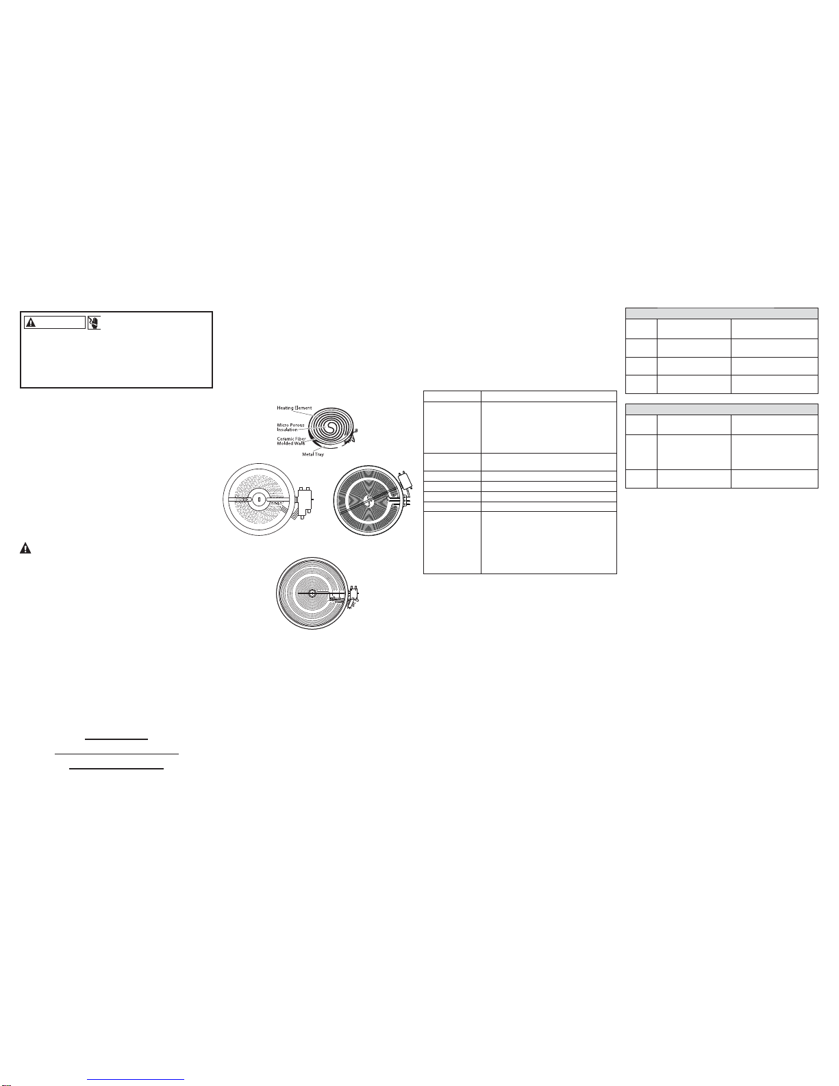
RADIANT HEATING ELEMENT SYSTEMS
The radiant heating element consists of a spiral wound resistance wire
DWWDFKHGWRPLFURSRURXVLQVXODWLRQZLWKPROGHGFHUDPLF¿EHUZDOOVLQD
corrosion protected metal tray.
TEMPERATURE LIMIT/HOT LIGHT SWITCH
The Temperature Limit/Hot Light Switch performs two functions:
1. Turns on HOT LIGHT as soon as glass temperature reaches 150º F. The
hot light will remain on until the glass surface above the heating unit
has cooled below 150º F (Even after surface unit switch has been turned
RȺ
2. Detects when glass temperature above a unit has exceeded its limit of
approximately 1031º F and disconnects power to that unit. When glass
temperature cools below 1031º F, the unit will turn back on.
The temperature limit/hot light switch can not be calibrated.
HOT SURFACE INDICATOR LIGHT
When the glass temperature reaches 150º F the Hot Surface Indicator
Light is activated to alert consumer that glass Surface is too hot to
touch. The Hot Surface Indicator Light Is turned on by an additional set of
contacts within the temperature limiter.
Tri-Ring Element
Single Element Dual Element
SERVICE MODE
Service Mode can be entered by the following steps:
1. Press and Hold the Front Right Burner ON/OFF key for 7 seconds
until tone is heard and “1” appears on the timer.
2. Press and Hold Rear Right Burner ON/OFF key for 7 seconds
until tone is heard and Software version appears on the timer.
DIAGNOSTICS MODE SUMMARY
The Table below describes what key provides what diagnostic
features each key will do.
Key Response
Left Rear + Displays failure codes on the Timer. Pressing
this key multiple times will cycle through
each failure code until dashes appear
showing the end of the codes. If no active
failures exist only dashes will be shown with
each press.
$OO2Ⱥ Pressing and holding for 5 seconds will clear
the Failure Code that is currently displayed.
Left Front + Turns on all the LEDs for 5 seconds.
Left Front - Exit Service Mode.
Right Front - Display main board software version
Right Front + Display Induction board #1 software version
Timer Select
RU7LPHU212)) ONLY use this when a mistake has been
made in setting the model number for a
service replacement board.
To clear the service model number, press and
hold for 7 seconds. Control will show SEt in
timer block, ready to reprogram the service
control’s model number.
FAILURE CODES
User Interface
Fault
Code Issue Description Possible Fixes
F1x UL “On” Indicator
Light/LED Failure Replace Display Board
XQGHU7RXFK%RDUG
F7x 8VHU,QWHUIDFH8,
Button Matrix Error Replace Touch Board
F82 8VHU,QWHUIDFH8,
Microprocessor Error Replace Display Board
XQGHU7RXFK%RDUG
Machine Control (MC)
Fault
Code Issue Description Possible Fixes
F6x UI cannot
communicate with
Machine Control
Check wires connecting UI
to MC. Replace Machine
Control. Replace Display
%RDUGXQGHU7RXFK%RDUG
F81 0DFKLQH&RQWURO0&
Microprocessor Error Replace Machine Control
NOTES:
If the touch board needs to be replaced it must be replaced in
combination with the glass; these two components come from the
factory as a single assembly. Do NOT attempt to reuse the glass
when replacing the touch board. The display board and its light
guides may be removed from the old touch board and installed
RQWRWKHQHZWRXFKERDUGDQGJODVV
If the display board needs to be replaced, the light guides need to
be transferred from the old display board to the new display board
before installing the new display board onto the touch board (and
JODVV(DFKRIWKHOLJKWJXLGHVLVKHOGLQSODFHZLWKVSULQJFOLSV
ORFNLQJDUPVZKLFKSURWUXGHWKURXJKWKHGLVSOD\ERDUG*HQWO\
squeeze together the clips on the outside of the smaller light
guides (on the large, circular light guides press the clips outwards
IURPWKHFHQWHUWRZDUGVWKHFLUFXODUULQJERG\DQGUHPRYHWKH
light guide from the display board; transfer it to the same location
on the replacement display board.
SEt – SETTING UP SERVICE REPLACEMENT CONTROLS
Service Replacement UIs must be set up with the appropriate
model number to function correctly.
1. After replacing the control, apply power to the unit.
2. Upon power up the UI will display the letters SEt after a few
seconds.
NOTE: All the LEDs may initially turn on for up to 10 seconds
before SEt appears on screen.
3. Using the Timer up (^DQGGRZQvNH\VVHOHFWWKHFRUUHFWFRGH
(AE2IRUWKLVPRGHO
4. Press and hold the Timer Select (or Timer Start on models
ZKHUHWKLVNH\LVDYDLODEOHIRUVHFRQGVWRVWRUHWKLVPRGHO
number in the control.
5. The control should restart and operate normally.
MODEL NUMBERS
ZEU36R
IMPORTANT
SERVICE INFORMATION
DO NOT DISCARD
Pub No. 31-17149 12-14 GE
CIRCUIT BOARD PIN-OUTS
User Interface (UI, Glass-mounted)
J1 Power Supply Input & Communications to
Machine Control
J1 Pin 1 7.5V DC Power
J1 Pin 2 *($&RPPXQLFDWLRQ%XVWR0DFKLQH&RQWURO
J1 Pin 3 Zero-Cross Detect
J1 Pin 4 Heating Enable. +5VDC Active
J1 Pin 5 NC
J1 Pin 6 NC
J1 Pin 7 NC
J1 Pin 8 Logic Ground
J6 Service/Diagnostics Port
J6 Pin 1 6HUYLFH9'&3RZHURXW
J6 Pin 2 6HUYLFH&RPPXQLFDWLRQ%XV*($
J6 Pin 3 Service Logic Ground
Machine Control (High Voltage and Power Control)
J201 Hot Light Inputs
J201 Pin 2 Hot Light Bi-metal from Element (W + BU wire @ Right Front element
J201 Pin 3 +RW/LJKW%LPHWDOIURP(OHPHQW:%5ZLUH#5LJKW5HDUHOHPHQW
J201 Pin 4 +RW/LJKW%LPHWDOIURP(OHPHQW:*<ZLUH#&HQWHUHOHPHQW
J201 Pin 5 +RW/LJKW%LPHWDOIURP(OHPHQW:2ZLUH#/HIW5HDUHOHPHQW
J201 Pin 6 +RW/LJKW%LPHWDOIURP(OHPHQW:<ZLUH#/HIW)URQWHOHPHQW
J501 & J506 L2 Relay Inputs/Outputs for Heating Element (Center)
J506 L2 Input for Element
J501 Pin 1 /2XWSXWWR(OHPHQW,QQHU5LQJ*<%.ZLUH#(OHPHQW
J501 Pin 2 NC
J501 Pin 3 /2XWSXWWR(OHPHQW0LGGOH5LQJ*<:ZLUH#(OHPHQW
J501 Pin 4 /2XWSXWWR(OHPHQW2XWHU5LQJ35ZLUH#(OHPHQW
J502 & J507 L2 Relay Inputs/Outputs for Heating Element (Left Front)
J507 L2 Input for Element
J502 Pin 1 /2XWSXWWR(OHPHQW<%.ZLUH#(OHPHQW
J502 Pin 2 L2 Output to Element NOT USED
J503 & J508
L2 Relay Inputs/Outputs for Heating Element (Right Front)
J508 L2 Input for Element
J503 Pin 1 /2XWSXWWR(OHPHQW,QQHU5LQJ%8<ZLUH#(OHPHQW
J503 Pin 2 /2XWSXWWR(OHPHQW0LGGOH5LQJ%8:ZLUH#(OHPHQW
J503 Pin 3 /2XWSXWWR(OHPHQW2XWHU5LQJ35<ZLUH#(OHPHQW
J504 & J509 L2 Relay Inputs/Outputs for Heating Element (Right Rear)
J509 L2 Input for Element
J504 Pin 1 /2XWSXWWR(OHPHQW%5%.ZLUH#(OHPHQW
J505 & J510 L2 Relay Inputs/Outputs for Heating Element (Left Rear)
J510 L2 Input for Element
J505 Pin 1 /2XWSXWWR(OHPHQW2%.ZLUH#(OHPHQW
K516 – K520 L1 (DLB) Relay Inputs/Outputs for Heating Elements
K516:NO,COM &20 /,QSXW12 /2XWSXWWR(OHPHQW*<ZLUH#&HQWHUHOHPHQW
K517:NO,COM &20 /,QSXW12 /2XWSXWWR(OHPHQW<ZLUH#/HIW)URQWHOHPHQW
K518:NO,COM &20 /,QSXW12 /2XWSXWWR(OHPHQW%8ZLUH#5LJKW)URQWHOHPHQW
K519:NO,COM &20 /,QSXW12 /2XWSXWWR(OHPHQW%5ZLUH#5LJKW5HDUHOHPHQW
K520:NO,COM &20 /,QSXW12 /2XWSXWWR(OHPHQW2ZLUH#/HIW5HDUHOHPHQW
Power Supply
J100 AC Power Inputs
J100 Pin 1 L2
J100 Pin 2 Earth Ground
J100 Pin 3 L1
J101 DC Power Outputs
J101 Pin 1 9'&3RZHURXW
J101 Pin 2 Logic Ground
J101 Pin 3 9'&3RZHURXW
J101 Pin 4 9'&3RZHURXW
J101 Pin 5 Logic Ground
J101 Pin 6 Zero-Cross Detect
Machine Control (Low-Level Logic)
J301 Power Supply Inputs & Misc. Hand-Shaking
J301 Pin 1 9'&3RZHULQ
J301 Pin 2 *($&RPPXQLFDWLRQ%XVWR8VHU,QWHUIDFH
J301 Pin 3 Logic Ground
J301 Pin 4 NC
J301 Pin 5 9'&3RZHULQ
J301 Pin 6 +HDWLQJ5HOD\(QDEOH9'&$FWLYH
J301 Pin 7 Zero-Cross Detect
J301 Pin 8 NC
RJ45 Service/Diagnostics Port
J1 Service Connector (External, accessible to Technician)
J1 Pin 1 6HUYLFH9'&3RZHURXW
J1 Pin 7 6HUYLFH&RPPXQLFDWLRQ%XV*($
J1 Pin 8 Service Logic Ground
J2 Internal Connector (Communicates to User Interface)
J2 Pin 1 6HUYLFH9'&3RZHURXW5HGZLUH
J2 Pin 2 6HUYLFH&RPPXQLFDWLRQ%XV*($:KLWHZLUH
J2 Pin 3 6HUYLFH/RJLF*URXQG%ODFNZLUH
31-17149 12-14 GE
Model Numbers - ZEU36R
IMPORTANT
SERVICE INFORMATION
DO NOT DISCARD
31-17149 12-14 GE
Model Numbers - ZEU36R
IMPORTANT
SERVICE INFORMATION
DO NOT DISCARD

Other manuals for 36 ELECTRIC RADIANT COOKTOP ZEU36R

2

Other GE Cooktop manuals

GE JP256BMBB User guide

GE

GE JP256BMBB User guide

GE Profile JP346 Manual

GE

GE Profile JP346 Manual

GE PP9830 User manual

GE

GE PP9830 User manual

GE JGP945SEKSS - 30" Sealed Burner Gas Cooktop Manual

GE

GE JGP945SEKSS - 30" Sealed Burner Gas Cooktop Manual

GE JGP628 User manual

GE

GE JGP628 User manual

GE Profile PP9036DJ Manual

GE

GE Profile PP9036DJ Manual

GE CP350STSS Manual

GE

GE CP350STSS Manual

GE JCP340 User manual

GE

GE JCP340 User manual

GE JGP336 User manual

GE

GE JGP336 User manual

GE Monogram ZEU30R User manual

GE

GE Monogram ZEU30R User manual

GE Monogram ZGU3650 User guide

GE

GE Monogram ZGU3650 User guide

GE JP655SK User instructions

GE

GE JP655SK User instructions

GE ZGU36L6D User manual

GE

GE ZGU36L6D User manual

GE CGP350 User manual

GE

GE CGP350 User manual

GE JP626CFCC Manual

GE

GE JP626CFCC Manual

GE Monogram ZEU769 User manual

GE

GE Monogram ZEU769 User manual

GE Profile PP975 Manual

GE

GE Profile PP975 Manual

GE JP340BJ User guide

GE

GE JP340BJ User guide

GE Thermostat Gas Ranges User manual

GE

GE Thermostat Gas Ranges User manual

GE Profile PGP990SENSS Manual

GE

GE Profile PGP990SENSS Manual

GE JIC100 User manual

GE

GE JIC100 User manual

GE Profile PHP900DM User manual

GE

GE Profile PHP900DM User manual

GE JP201CBSS User guide

GE

GE JP201CBSS User guide

GE JGP319 User manual

GE

GE JGP319 User manual

Popular Cooktop manuals by other brands

hestan KEC 30 installation manual

hestan

hestan KEC 30 installation manual

Heartland Appliances Heartland Induction Cooktop Installation and user manual

Heartland Appliances

Heartland Appliances Heartland Induction Cooktop Installation and user manual

Omega OCC64KZTGG instruction manual

Omega

Omega OCC64KZTGG instruction manual

Whirlpool W5CE1522FB01 installation instructions

Whirlpool

Whirlpool W5CE1522FB01 installation instructions

Thermador CIT151DS installation instructions

Thermador

Thermador CIT151DS installation instructions

Lumme LU-3637 user manual

Lumme

Lumme LU-3637 user manual

Capital PSCT484BG installation guide

Capital

Capital PSCT484BG installation guide

Fisher & Paykel CE302 Series Installation instructions and user guide

Fisher & Paykel

Fisher & Paykel CE302 Series Installation instructions and user guide

CombiSteel 7478,0515 instruction manual

CombiSteel

CombiSteel 7478,0515 instruction manual

Wolf SRT364C Specifications

Wolf

Wolf SRT364C Specifications

Mr. Induction SR-650C instruction manual

Mr. Induction

Mr. Induction SR-650C instruction manual

KitchenAid KGCP462 Use & care guide

KitchenAid

KitchenAid KGCP462 Use & care guide

Maytag CCG2420 Service manual

Maytag

Maytag CCG2420 Service manual

Whirlpool GJC3654RB02 parts list

Whirlpool

Whirlpool GJC3654RB02 parts list

Kenmore Sears 95629 Use and care and safety manual

Kenmore

Kenmore Sears 95629 Use and care and safety manual

Miele KM 443 operating instructions

Miele

Miele KM 443 operating instructions

Angelo Po 0N0PE4 user manual

Angelo Po

Angelo Po 0N0PE4 user manual

duxtop E200A user manual

duxtop

duxtop E200A user manual

manuals.online logo
manuals.online logoBrands
  • About & Mission
  • Contact us
  • Privacy Policy
  • Terms and Conditions

Copyright 2025 Manuals.Online. All Rights Reserved.