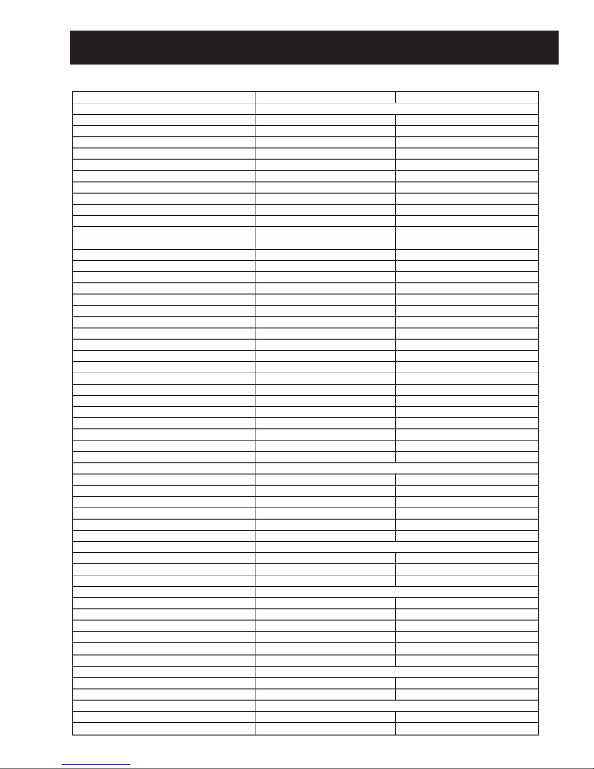
GE GLDA690 How to use

GE Appliances
General Electric Company
Louisville, Kentucky 40225
31-9138
GE Built-In
Dishwasher
GLDA690
GLDA696
Technical Service Guide
June 2006
GE Consumer & Industrial

– 2 –
IMPORTANT SAFETY NOTICE
The information in this service guide is intended for use by
individuals possessing adequate backgrounds of electrical,
electronic, and mechanical experience. Any attempt to repair a
major appliance may result in personal injury and property
damage. The manufacturer or seller cannot be responsible for the
interpretation of this information, nor can it assume any liability in
connection with its use.
WARNING
To avoid personal injury, disconnect power before servicing
this product. If electrical power is required for diagnosis or test
purposes, disconnect the power immediately after performing the
necessary checks.
RECONNECT ALL GROUNDING DEVICES
If grounding wires, screws, straps, clips, nuts, or washers used to
complete a path to ground are removed for service, they must be
returned to their original position and properly fastened.
GE Consumer & Industrial
Technical Service Guide
Copyright © 2006
All rights reserved. This service guide may not be reproduced in whole or in part
in any form without written permission from the General Electric Company.

– 3 –
Table of Contents
Bottom Door Seal .............................................................................................................................................................19
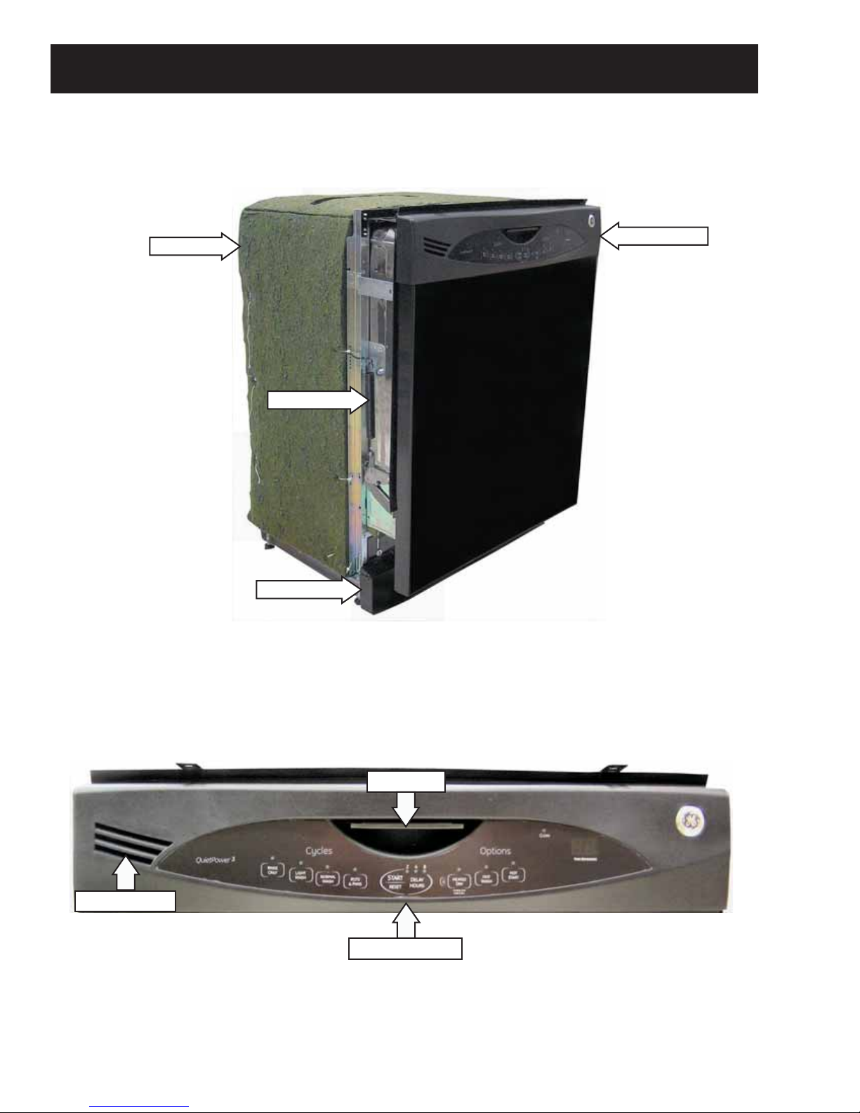
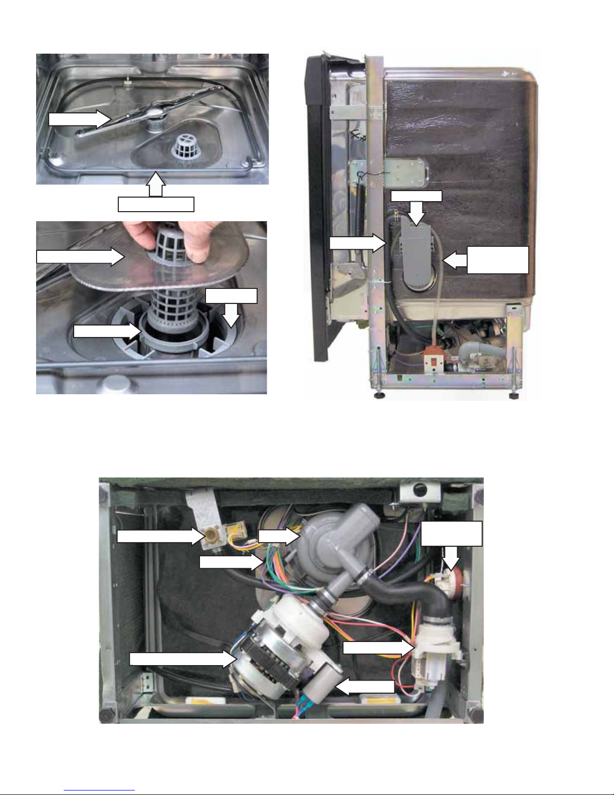
Component Locator Views........................................................................................................................................... 8
Control Assembly..............................................................................................................................................................12
Control Features............................................................................................................................................................... 6
Control Panel ...................................................................................................................................................................... 11
Detergent/Rinse Module................................................................................................................................................16
Diagnostics and Service Information...................................................................................................................... 28
Dishwasher Components..............................................................................................................................................11
Door Assembly...................................................................................................................................................................17
Door Latch and Release Assembly........................................................................................................................... 13
Door Panel............................................................................................................................................................................11
Door Switch Assembly ...................................................................................................................................................15
Drain Pump Assembly....................................................................................................................................................24
Fill Funnel..............................................................................................................................................................................21
Heating Element................................................................................................................................................................19
Introduction......................................................................................................................................................................... 5
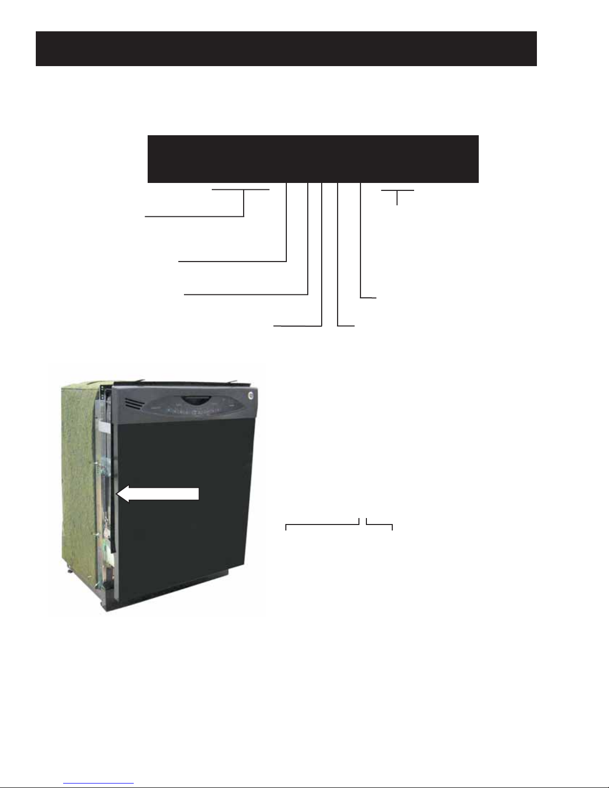
Nomenclature .................................................................................................................................................................... 4
Pressure Switch .................................................................................................................................................................23
Schematics and Wiring Diagrams............................................................................................................................30
Service Test Mode.............................................................................................................................................................28
Specifications .....................................................................................................................................................................28
Static Dry System.............................................................................................................................................................12
Sump Assembly.................................................................................................................................................................27
Thermistor............................................................................................................................................................................26
Troubleshooting ...............................................................................................................................................................29
Tub Seal.................................................................................................................................................................................18
Warranty ..............................................................................................................................................................................31
Wash Pump Assembly ...................................................................................................................................................25
Water Inlet Valve...............................................................................................................................................................22

– 4 –
Platform
4-6 = GE tall tub
G L D A 6 9 0 M B B
Product Type
GLD = GE long door
Exterior Color
BB = Black
CC = Bisque
SS = Stainless Steel
WW = White
Model Year Designator
Model Number
The nomenclature plate is located on
the left side of the tub wall, inside the
door jamb.
The mini-manual is located in a
plastic bag taped behind the toe kick.
Nomenclature
The letter designating
the year repeats every
12 years.
Example:
T - 1974
T - 1986
T - 1998
Serial Number
The first two characters of the serial number
identify the month and year of manufacture.
Example: AL123456S = January, 2006
A- JAN 2006 - L
D - FEB 2005 - H
F - MAR 2004 - G
G - APR 2003 - F
H - MAY 2002 - D
L - JUN 2001 - A
M - JUL 2000 - Z
R - AUG 1999 - V
S - SEP 1998 - T
T - OCT 1997 - S
V - NOV 1996 - R
Z - DEC 1995 - M
Nomenclature
Door
0 = Color door
6 = Stainless door
Feature Pack
ADA Compliant

– 5 –
Introduction
GLDA690MWW GLDA696MSS
FEATURES
ADA Compliant Yes Yes
Door Styl
e
Long door/Tall tub Long door/Tall tub
Energy Star® Qualified Yes Yes
Tub and Door Line
r
Stainless Steel Stainless Steel
Control Type Electronic Light-Touch Electronic Light-Touch
Automatic Temperature Control Yes Yes
Automatic Temperature Sensing Yes Yes
Dual Pumps and Motors Yes Yes
Last Cycle Memor
y
Yes Yes
Wash Arms 3-Direct Feed 3-Direct Feed
Wash Levels 6 6
Water Filtration System 100% Water Filtration 100% Water Filtration
Cycles / Options 4/4 4/4
Light Wash Yes Yes
Normal Wash Yes Yes
Pots & Pans Yes Yes
Rinse Onl
y
Yes Yes
Delay Star
t
2/4/8-Hr. 2/4/8-Hr.
Heated Dry On/Of
f
Yes Yes
Hot Wash Yes Yes
HotStart™ Yes Yes
Lock Pad Yes Yes
Start / Cancel / Reset Pad Yes Yes
Cup Shel
f
2 Plastic with 1 StemSafe™ 2 Plastic with 1 StemSafe™
Lower Rack Deluxe Towerless Deluxe Towerless
Silverware Baske
t
1 Piece Super with 1 Cell Cove
r
1 Piece Super with 1 Cell Cove
r
Upper Rack Tiered Tiered
Cycle Countdown 2 Digit Displa
y
2 Digit Displa
y
Touchpads / Knobs 9 Touchpads 9 Touchpads
120 ° Inlet Water Capabilit
y
Yes Yes
Calrod Heate
r
Multi-Wattage Multi-Wattage
ECONOMICAL / QUIET
Door Insulation and Bitumen Yes Yes
Outer Wrap Full-wrap Blanke
t
Full-wrap Blanke
t
QuietPower™ Moto
r
Yes Yes
Sound Insulation Package QuietPower™ 3 58 dB
A
QuietPower™ 3 58 dB
A
Stainless Steel Interio
r
Yes Yes
Tub Collar Trim Yes Yes
APPEARANC
E
Installation Built-In Built-In
Color Appearance "WW" "BB" "CC" Stainless Steel
Control Color / Styl
e
"WW" "BB" "CC" / Electronic Black / Electronic
WEIGHTS & DIMENSIONS
Approximate Shipping Weight 100 lb 100 lb
Net Weight (lbs.) 95 lb 95 lb
Overall Depth 24 in 24 in
Overall Heigh
t
32.35 in 32.35 in
Overall Height With Legs Extended (In.) 34.5 34.5
Overall Width 24 in 24 in
POWER / RATINGS
Calrod Heater Watts 875 Max. 875 Max.
Volts/Hertz/Amps 120V 60 Hz 9.1
A
120V 60 Hz 9.1
A
WARRANT
Y
Parts Warranty Limited 1-year entire applianc
e
Limited 1-year entire applianc
e
Labor Warranty Limited 1-year entire appliance Limited 1-year entire appliance

– 6 –
Throughout this manual, features and appearance may vary from your model.
Control Features

– 7 –
About the dishwasher control panel.
Cycle Sequence
Water Time
Cycles (approx.) (approx.) Cycle Sequence
POTS & PANS
7.4 gal. 85 min. Rinse Rinse Rinse Rinse Rinse Wash Rinse Rinse
NORMAL WASH
5.3 gal. 56 min. Rinse Rinse Rinse Wash Rinse Rinse
LIGHT WASH
4.2 gal. 33 min. Rinse Rinse Wash Rinse Rinse
RINSE ONLY
2.1 gal. 7 min. Rinse Rinse
Drying Options
HEATED DRY ON Adds approximately 38 minutes to the cycle.
(Not available on the RINSE ONLY cycle.)
HEATED WASH Options
HEATED WASH ON Adds approximately 15 minutes to the main wash cycle. Energizes heater during
main wash cycle.
(Not available on the RINSE ONLY cycle.)
HEATED START Options
HEATED START ON Adds approximately 22 minutes to the cycle by adding 2 pre-rinses. The first is a
normal pre-rinse to purge the water supply lines. The second pre-rinse lasts 15
minutes with the heater energized to heat the tub and dishware. (Not available on
the RINSE ONLY cycle.)

– 8 –
Front View
Component Locator Views
Control Panel View
Insulation
Door Spring
Access Panel
Control Panel
Door Latch
Control Assembly
Static Dry Vent
(Continued next page)

– 9 –
Interior View (With Racks)
Detergent/Rinse Module Compartment View
Top Rack
Bottom Rack
Detergent/Rinse Module
Static Dry Vent
Detergent Compartment
Compartment Lid
Sight Glass
Rinse Agent Cap
Rinse Agent Outlet
(Continued next page)

– 10 –
Interior View of Basin (With Racks Removed) Right Side View (Insulation Removed)
Bottom View (Looking Up)
Sump
Drain Pump
Spray Arm
Heating Element
Filter Assembly
Micro-Filter
Clamp Nut
Fill Hose
Pressure
Switch Hose
Fill Funnel
Wash Pump Assembly
Capacitor
Pressure
Switch
Thermistor
Water Inlet Valve
Front
Back

– 11 –
Dishwasher Components
Control Panel
To remove the control panel:
Remove the door panel. (See Door Panel.)
Turn the static dry vent cover counterclockwise
and remove it.
1.
2.
Remove the six ¾-in. long Phillips-head screws
that attach the control panel to the door
assembly.
3.
Disconnect the 3 wire harnesses from the
control module.
4.
Vent
Cover
Door Panel
The door panel covers the door to the dishwasher
and must be removed to access the control panel,
detergent/rinse module, bottom door seal, and
heating element.
To remove the door panel, remove 6 Phillips-head
screws, then lower the door panel from the control
panel.

– 12 –
Note:
Inspect the cover for hard water/lime deposits
or debris and clean if necessary.
If the control panel gasket shows obvious signs
of wear or damage, replace the gasket.
If the vent cover O-Ring shows obvious signs of
wear or damage, replace the static dry vent.
•
•
•
Static Dry Vent
Anchor Pin
O-Ring
Control Assembly
The control assembly consists of the control circuit
board, control module, and module cover.
To remove the control assembly:
Remove the static dry vent cover. (See Static Dry
System.)
Remove the 12 Phillips-head screws that attach
the control circuit board to the control panel.
1.
2.
Remove the 2 Phillips-head screws that hold the
control module cover to the control panel.
3.
(Continued next page)
Static Dry System
The static dry system operates through a vent
located in the control panel. The vent allows hot air
to exit the dishwasher tub and gradually remove
moisture.
To remove the vent it will be necessary to access the
control panel. (See Control Panel steps 1 through 3.)
The vent is pressed in place over an anchor pin and
positioned in the vent outlet recess located on the
inside of the control panel.
Vent Outlet Recess

– 13 –
Remove the 6 Philliips-head screws from the
control module.
Release the 2 top tabs and remove the control
module from the bottom 3 retainers.
4.
5.
Tabs
Retainers
Door Latch and Release Assembly
The door latch is permanently mounted to the top
of the dishwasher and is not replaceable. When
the door is in the closed position, the door latch
has dropped into place in front of the door switch
housing assembly and has pressed the switch
plunger down. This action holds the door firmly
against the seal, and the normally open contacts of
the door switches are closed.
The door release assembly is located on the inside
of the control panel. When the release handle is
pressed upward, it raises the door latch to clear the
front of the door switch housing assembly, releasing
the door.
To remove the door release assembly it will be
necessary to access the control panel. (See Control
Panel steps 1 through 3.) The door release is held to
the control panel with 2 Phillips-head screws.
Caution: The door latch assembly may come apart.
Use care to assure the latch spring is not lost during
removal, handling, or installation.
To reassemble and reinstall the door latch
assembly:
Slide the latch spring onto the latch-block hinge
pin and hook the spring into the hole in the latch
block.
1.
Latch Spring
Latch Block
Hinge Pin
Hole
(Continued next page)
Note: Wiring harness on the control assembly does
not disconnect. Control assembly must be replaced
as a unit.
Remove the control circuit board, control
module, and control module cover.
6.

– 14 –
Snap the latch block into the latch bracket
making sure the spring arm rests in the channel
in the latch bracket.
2.
Latch Bracket
Channel
Latch Block
Rotate the latch block to compress the spring.3.
Latch Block
With the raised center bar of the latch handle
toward the latch block, insert the latch handle
hinge pins into the holes in the latch bracket.
4.
Raised
Center
Bar
Latch Block
Latch Handle
Insert this latch assembly, including the handle,
into the escutcheon cutout with the latch handle
side toward the bottom of the escutcheon.
Assure that the top rib of the handle is tucked
under the top edge of the cutout and attach the
assembly with 2 Phillips-head screws.
5.
6.
Screws
Latch Handle
Top Rib
Top of
Escutcheon
Top Edge of Cutout

– 15 –
Door Switch Assembly
The door switch assembly consists of 2 switches
activated by a spring loaded plunger. One door
switch connects or disconnects the Line (hot) side of
120 VAC. The other switch connects or disconnects
the Neutral side of 120 VAC. When the door is in
the closed position, the door latch has dropped into
place in front of the door switch assembly and has
pressed the switch plunger down. This action holds
the door firmly against the seal, and the normally
open contacts of the door switches are closed.
To remove the door switch assembly:
Remove the control panel. (See Control Panel.)
Remove the 2 Phillips-head screws that hold the
door switch assembly to the top of the door.
1.
2.
Caution: When removing the plunger, the spring is
not secured and will pop off. To secure, place your
hand over the spring when removing the plunger.
Remove the plunger and the spring.4.
Using a small flat-blade screwdriver, lift the door
switch cover at the 2 tabs on each side, the 2
inner tabs, and the bottom tab.
3.
Lift up the interlock switches to remove. These
switches are replaceable (Part # WD21X10224).
Note:
Upon reassembly, ensure that the notched side
of the plunger is placed towards the plunger
guide in the switch housing.
Ensure that the bottom of the spring is
positioned on top of the bottom guide, and that
the plunger slides freely.
5.
•
•
Door Switch Cover
Plunger
Spring
Plunger Guide
Bottom Guide

– 16 –
Detergent/Rinse Module
The control panel must be removed to access the
detergent/rinse module. (See Control Panel.)
The detergent/rinse module is connected by 2 wires
and held in place by 6 Phillips head screws and 2
brackets.
The detergent/rinse module operates on 120 VAC
and has an approximate resistance value of 2.6K Ω.
The detergent/rinse module automatically
dispenses both the detergent and the rinse agent
at the appropriate times. The module is activated 2
times during a wash cycle. Detergent is dispensed
at the beginning of the main wash cycle and rinse
agent at the beginning of the final rinse.
Operation of the detergent/rinse module can be
checked by using the service test mode. (See Service
Test Mode.)
The first time the module is activated, the lever
slides up the right-hand path of the connecting rod
(1). This action releases the detergent cover.
When deactivated, the lever returns down the left-
hand path and comes to rest under the notch (2) in
the center of the connecting rod.
At the second activation, the lever lifts the
connecting rod by the notch. This action lifts the
rinse dispenser plunger (3) and releases the rinse
agent. When deactivated, the lever returns to its
original starting position.
1
2
3
Bracket
Bracket
Wires
Note: Make sure the rubber seal is retained in the
recessed groove before reinstalling the module to
the door assembly.
Seal

– 17 –
Door Assembly
To remove the door assembly:
Disconnect power.
Partially remove the dishwasher from its
installation to access the door springs.
Remove the control panel. (See Control Panel.)
Remove the detergent/rinse module. (See
Detergent/Rinse Module.)
Remove the door latch assembly. (See Door
Latch Assembly.)
Remove the thermistor wires from the tape
attached to the door panel.
Remove the 8-mm nut, Phillips-head screw,
and ground wire from the right side door hinge
assembly.
1.
2.
3.
4.
5.
6.
7.
Caution: When one or both of the door springs are
disconnected, the door may fall to the floor. Care
must be taken to prevent damage to the door.
Pull the spring and spring bolt key from the
mounting bracket.
Remove the bottom of the spring loop from the
hinge arm stud.
9.
10.
Note: The following describes the procedure to
remove the right side of the door assembly from the
hinge assembly. The procedure to remove the left
side is identical.
Mark the position of the spring bolt key in the
mounting bracket with a felt-tip marker.
8.
Nut and Screw
Thermistor Wires
Tape
Ground Wire
Key
Bracket
Loop
Stud
(Continued next page)

– 18 –
Tub Seal
The dishwasher tub seal prevents water leakage.
The seal is fitted in a seal channel that lines the rim
of the dishwasher tub.
To remove the tub seal:
Open the dishwasher door.
Grasp one end of the dishwasher tub seal and
peel it away from the seal channel.
1.
2.
Open the dishwasher door approximately 30
degrees.
Lift the bottom hinge arm up from the bottom
hinge, far enough to expose the hook.
11.
12.
Position hinge arm assembly to hang freely as
shown.
13.
Repeat steps 8 through 13 on the left side of the
door panel.
Remove the remaining three 8-mm nuts and
Phillips-head screws that hold the door panel to
the hinge assembly.
14.
15.
Reverse the above procedure to install.
Note: When installing the tub seal, make sure it is
seated properly in the seal channel. Run your finger
over the seal to make sure it is smooth and even for
a proper seal. A correctly installed gasket will have
both ends of the gasket equidistant from the bottom
of the tub.
3.
Bottom Hinge
Hinge Arm
Hinge Arm
Assembly
Tub Seal
Seal Channel

– 19 –
Heating Element
The heating element maintains water temperature
during the wash and rinse cycles and heats the air
during the static dry cycle.
The heater has an approximate resistance value of
21.2 Ω.
Operation of the heating element can be checked
by using the service test mode. (See Service Test
Mode.) Allow one or two minutes before opening the
dishwasher door and note if heat is present.
To remove the heating element:
Remove the door panel. (See Door Panel.)
Remove the bottom rack.
Remove the 2 Phillips head screws, washers,
and the access panel.
1.
2.
3.
Bottom Door Seal
The bottom door seal prevents water leakage.
The seal is fitted in a pinched metal groove at the
bottom of the dishwasher door.
WARNING: The pinched metal groove is sharp.
Wear Kevlar gloves when removing or installing the
bottom door seal. Failure to comply may result in
personal injury.
It is necessary to remove the door assembly to
access the bottom door seal. (See Door Assembly.)
The seal is pulled out from the pinched metal
groove.
Door Seal
Pinched Metal Groove
Remove the 2 Phillips-head screws and lower
the water valve from the front brace.
Remove the 2 Phillips-head screws and lower
the junction box from the front brace.
4.
5.
(Continued next page)
To install the bottom door seal it will be necessary
to open the pinched metal groove. Make sure the
seal is seated properly in the metal groove before
pinching closed. Run your finger over the groove to
make sure it is smooth and even for a proper seal.
Water Valve
Junction Box
Front Brace

– 20 –
Remove the 6 Phillips-head screws and the front
brace from the dishwasher.
6.
Locate the wires leading to the heating element
terminals and pull down the 2 nylon terminal
covers.
Disconnect the 2 wires from the heating
element.
7.
8.
Remove the outer 8 mm nut that attaches the
ground wire to the element mounting bolt.
9.
Lift the right side of the element and release it
from the 2 retainers.
11.
Remove the inner 8 mm nut, washer, and spacer
that attaches the element to the bottom of the
tub.
10.
Heater Wire Heater Wire
Nylon Terminal Covers
Outer Nut
Ground
Wire
Washer Inner Nut
Spacer
Other manuals for GLDA690
4
This manual suits for next models
3
Table of contents
Other GE Dishwasher manuals

GE
GE Profile CDW9000 Series User manual

GE
GE GDF510PSDSS User manual

GE
GE GSD1821 User manual

GE
GE Profile PDW8400 Series User manual

GE
GE GDF 610 Series User manual

GE
GE GSD3900G00BB User manual

GE
GE CDW9380NSS Manual

GE
GE Cafe CDWT280VSS User manual

GE
GE 206C1559P195 User manual

GE
GE GBF655 Series User manual