GE Monogram ZBD1870 User manual

Appliances
Installation Instructions
If gou have questions, call 800.626.2000 or visit our website at: www.monogram.com
Built-In Dishwashers
ZBD1850*
ZBD1870
*For ZBD1850 also refer to the
instructions provided on the template
packed with that model

Safetg Information
BEFORE YOU BEGIN
Read these instructions completelg and
curefullg.
IM PORTANT Observeallgoverningcodesand
ordinances.
Note to Installer - Besure to leave these instructions for the
consumer's and local inspector's use.
Note to Consumer - Keep these instructions with gour
Owner's Manual for future reference.
Skill Level -Installation of this dishwasher requires
basic mechanical, electrical and plumbing skills. Proper
installation is the responsibility of the installer. Product
failure due to improper installation is not covered under
the GEAppliance Warranty. See warranty information.
Completion Time - 1 to 3 Hours. New installations require
more time than replacement installations.
I L J I'_ t'_ I"1"1" A k I'It"
I m i"%Ji_ I _1_1|- The dishwasherMUST
be installedtoallowforfutureremovalfromtheenclosure
if service isrequired.
If gou received a damaged dishwasher, gou should
immediatelg contact gour dealer or builder.
Optional Accessories - Seethe Owner's Manual for available
custom panel kits.
READ CAREFULLY.
KEEP THESE INSTRUCTIONS.
FOR YOUR SAFETY
Read and observe all CAUTIONSand WARNINGSshown
throughout these instructions.
While performing installations described in this booklet,
gloves and either safetg glasses or goggles should be worn.
For Monogram local service in gour area, 1.800.444.1845.
For Monogram service in Canada 1.888.880.3030.
For Monogram Parts and Accessories, call 1.800.626.2002.
CONTENTS
Installation Preparation
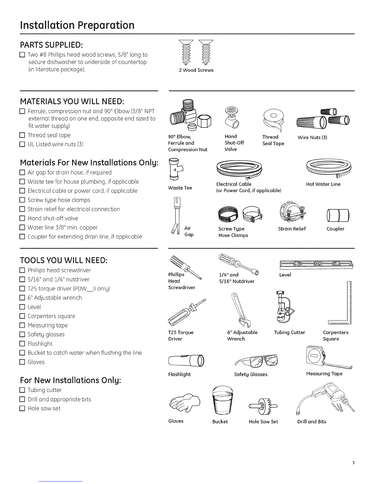
Parts Supplied ...................................................................................................5
Materials You Will Need ...............................................................................5
Tools You Will Need ........................................................................................5
Prepare Dishwasher Enclosure .................................................................4
Drain Requirements .......................................................................................4
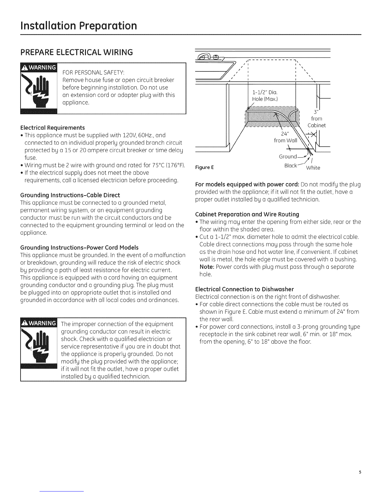
Prepare Electrical Wiring .............................................................................5
Prepare Hot Water Line ................................................................................6
Installation Instructions
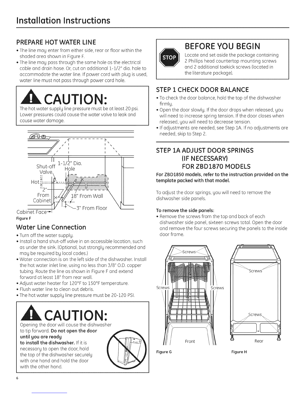
Step 1, Check Door Balance .......................................................................6
Step 1A, Adjust Door Springs .....................................................................6
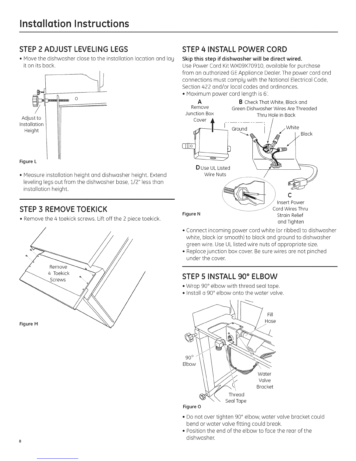
Step 2,Adjust Leveling Legs .......................................................................8
Step 3, Remove Toekick ................................................................................8
Step 4, Install Power Cord ...........................................................................8
Step
Step
Step
Step
Step
Step
Step
Step
Step
Step
Step
Step
Step
Step
5, Install 90° Elbow ...............................................................................8
6, Position Water Line and House Wiring ..................................9
7, Install Drain Hose Through Cabinet ........................................9
8,Slide Dishwasher Partiallg Into Cabinet ................................9
9, Position Dishwasher Under Countertop ............................10
!0, Level Dishwasher .......................................................................!!
11,Secure Dishwasher ToCabinet ............................................11
!2, Connect Water Supplg ............................................................12
!5, Connect Drain Line ....................................................................!2
!/4,Connect Power Supplg ............................................................!5
15, Pre-TestChecklist .......................................................................15
!6, Dishwasher Wet Test ................................................................14
17, Replace Toekick ..........................................................................!/4
!8, Literature ........................................................................................!/4

installation Preparation
PARTS SUPPLIED:
[] Two #8 Phillips head wood screws, 5/8" long to
secure dishwasher to underside of countertop
(in literature package). 2 Wood Screws
MATERIALS YOU WILL NEED:
[] Ferrule, compression nut and 90° Elbow (3/8" NPT
external thread on one end, opposite end sized to
fit water supplg)
[] Thread seal tape
[] ULListed wire nuts (3)
Materials For New Installations Only:
[] Air gap for drain hose, if required
[] Waste tee for house plumbing, if applicable
[] Electrical cable or power cord, if applicable
[] Screw type hose clamps
[] Strain relief for electrical connection
[] Hand shut-off valve
[] Water line 3/8" min. copper
[] Coupler for extending drain line, if applicable
90° Elbow, Hand Thread Wire Nuts {3)
Ferrule and Shut-Off Seal Tape
Compression Nut Valve
Waste Tee
Air
Gap
Electrical Cable
{or Power Cord, if applicable) Hot Water Line
Screw Tgpe Strain Relief Coupler
Hose Clamps
TOOLS YOU WILL NEED:
[] Phillips head screwdriver
[] 5/!6" and !/4" nutdriver
[] T25torque driver (PDW Ilonlg)
[] 6"Adjustable wrench
[] Level
[] Carpenters square
[] Measuring tape
[] Safetg glasses
[] Flashlight
[] Bucket to catch water when flushing the line
[] Gloves
For New Installations Only:
[] Tubing cutter
[] Drilland appropriate bits
[] Holesaw set
Phillips
Head
Screwdriver
f
T25 Torque
Driver
Flashlight
Gloves
5/16" Nutdriver Level
6" Adjustable Tubing Cutter Carpenters
Wrench Square
Safetg Glasses Measuring Tape
Bucket Hole Saw Set Drill and Bits

installation Preparation
PREPARE DISHWASHER ENCLOSURE
34-1/2"+ 1/2"
Underside of -
Countertop
to Floor
Floor MUST
be Evenwith
Room Floor
Figure A
18" Max.
Square
and
Plumb
Plumbing and Electric Service
Must Enter Shaded Area
• The rough cabinet opening must be at least 24" deep, 17-5/8"
to 18" wide and approximately 34-1/2" high from floor to
underside of the countertop.
DRAIN REQUIREMENTS
• Followlocalcodesand ordinances.
• Do notexceedi0'distancetodrain.
Do notconnectdrainlinesfromotherdevicestothe
dishwasherdrainhose.
NOTE:Airgap must be usedifwasteteeordisposerconnection
islessthan 18"above floortopreventsiphoning.
DETERMINE DRAIN METHOD
The type of drain installation depends on the following
questions.
[] Dolocal codes or ordinances require an air gap?
[] Iswaste tee lessthan 18" above floor?
If the answer to either question isYES,Method 1 MUST
be used.
• If the answers are NO,either method may be used.
CABINET PREPARATION
• Drill a 1-1/2" diameter hole in the cabinet wall within
the shaded areas shown in FigureA for the drain hose
connection. The hole should be smooth with no sharp edges.
IMPORTANT:When connecting
drain line to disposer, check to be _ 4--- Remove
sure that drain plug has been [_u Hopper
removed. DISHWASHERWILL NOT Plug
DRAINIF PLUGISLEFTIN PLACE.
• The dishwasher must be installed so that drain hose is no
more than 10' in length for proper drainage.
I G
To reduce the risk of electric shock, fire, or injury to persons, the
installer must ensure that the dishwasher is completelg enclosed
at the time of installation.
CLEARANCES: When
installed into a corner,
allow 2" min. clearance
between dishwasher and
adjacent cabinet, wall or
other appliances. Allow
25-5/8" min. clearance
from the front of the
dishwasher for door
opening. Figure B
Figure B
S Countertop
25-5/8"
\
,_ Clearance,!or Door
/Opening 2 Minimum
_/-'.eg A ____ ra
Figure C
Method 1 - Air 6ap with Waste Tee or Disposer
An air gap must be used when required bg local codes and ordinances.
The air gap must be installed according to manufacturer's instructions.
Figure D
Method 2 - Drain Hose Routing
When not using an air gap, the drain hose must be routed to form a high
loop of at least 32" to prevent siphoning. See Step 15 on page 10.
CAUTIO :
An air gap MUSTBEUSEDif the drain hose is connected to
waste tee or disposer lower than 18" above the floor level.
Failureto provide the proper drain connection height with an
air gap or 32" minimum high drain loop will result in improper
draining of the dishwasher, which may cause damage.

installation Preparation
PREPARE ELECTRICAL WIRING
FORPERSONALSAFETY:
Remove house fuse or open circuit breaker
before beginning installation. Do not use
an extension cord or adapter plug with this
appliance.
Electrical Requirements
• This appliance must be supplied with 120V,60Hz.,and
connected to an individual properly grounded branch circuit
protected by a 15 or 20 ampere circuit breaker or time delay
fuse.
• Wiring must be 2wire with ground and rated for 75°C(176°F).
• Ifthe electrical supply does not meet the above
requirements, call a licensed electrician before proceeding.
Grounding Instructions-Cable Direct
This appliance must be connected to a grounded metal,
permanent wiring system, or an equipment grounding
conductor must be run with the circuit conductors and be
connected to the equipment grounding terminal or lead on the
appliance.
Grounding Instructions-Power Cord Models
This appliance must be grounded. In the event of a malfunction
or breakdown, grounding will reduce the risk of electric shock
by providing a path of least resistance for electric current.
This appliance is equipped with a cord having an equipment
grounding conductor and a grounding plug. The plug must
be plugged into an appropriate outlet that is installed and
grounded in accordance with all local codes and ordinances.
The improper connection of the equipment
grounding conductor can result in electric
shock. Check with a qualified electrician or
service representative if you are in doubt that
the appliance is properly grounded. Do not
modify the plug provided with the appliance;
if it will not fit the outlet, have a proper outlet
installed by a qualified technician.
I
I
I
-i x
I x
I \ \
1 \
t x
1-1/2" Dia.
Hole (Max.)
from
Cabinet
I
Figure E Black White
For models equipped with power cord: Do not modify the plug
provided with the appliance; if it will not fit the outlet, have a
proper outlet installed by a qualified technician.
Cabinet Preparation and Wire Routing
• The wiring may enter the opening from either side, rear or the
floor within the shaded area.
• Cut a !-!/2" max. diameter hole to admit the electrical cable.
Cable direct connections may pass through the same hole
as the drain hose and hot water line, if convenient. If cabinet
wall ismetal, the hole edge must be covered with a bushing.
Note: Power cords with plug must pass through a separate
hole.
Electrical Connection to Dishwasher
Electrical connection is on the right front of dishwasher.
Forcable direct connections the cable must be routed as
shown in Figure E.Cable must extend a minimum of 24" from
the rear wall.
Forpower cord connections, install a 3-prong grounding type
receptacle in the sink cabinet rear wall, 6" min. or 18" max.
from the opening, 6" to 18" above the floor.

Installation Instructions
PREPARE HOT WATER LINE
The line may enter from either side, rear or floor within the
shaded area shown in Figure F.
The line may pass through the same hole asthe electrical
cable and drain hose. Or,cut an additional 1-1/2" dia. hole to
accommodate the water line. If power cord with plug is used,
water line must not puss through power cord hole.
CAUTION:
The hot water supply line pressure must be at least 20 psi.
Lower pressures could cause the water valve to leak and
cause water damage.
I \
I \
I \ \
From
Cabinet
Cabinet Face
Figure F
3" From Floor
Water Line Connection
Turn off the water supply.
Install a hand shut-off valve in an accessible location, such
as under the sink. (Optional, but strongly recommended and
may be required by local codes.)
Water connection is on the left side of the dishwasher. Install
the hot water inlet line, using no less than 3/8" O.D.copper
tubing. Route the line as shown in Figure Fand extend
forward at least 18"from rear wall.
Adjust water heater for !20°F to !50°F temperature.
Flush water line to clean out debris.
The hot water supply line pressure must be 20-120 PSI.
CAUTIO :
Opening the door will cause the dishwasher
to tip forward. Do not open the door
untilyou are ready
to install the dishwasher. If it is
necessary to open the door, hold
the top of the dishwasher securely
with one hand and hold the door
with the other hand.
BEFORE YOU BEGIN
Locate and set aside the package containing
2 Phillips head countertop mounting screws
and 2 additional toekick screws (located in
the literature package).
STEP 1 CHECK DOOR BALANCE
To check the door balance, hold the top of the dishwasher
firmly.
Open the door slowly. If the door drops when released, you
will need to increase spring tension. If the door closes when
released, you will need to decrease tension.
If adjustments are needed, see Step 1A.If no adjustments are
needed, skip to Step 2.
STEP 1A ADJUST DOOR SPRINGS
(IF NECESSARY)
FOR ZBD1870 MODELS
For ZBD1850 models, refer to the instruction provided on the
template packed with that model.
To adjust the door springs, you will need to remove the
dishwasher side panels.
To remove the side panels:
• Remove the screws from the top and back of each
dishwasher side panel, sixteen screws total. Open the door
and remove the four screws securing the panels to the inside
door frame.
Screws Screws
/
Y
-- Screws
• crews
Front Rear
Figure G Figure H

Installation Instructions
Lay the dishwasher on its back. Removethe four screws
securing the toekick to the dishwasher, and remove the
toekick.
Remove the single screw just above and to the side of each
front leveling leg.
Removethe side panels and set the dishwasher upright.
To adjust the door springs:
Pullthe spring adjustment pin out of the holes, insert in the
next highest or lowest hole and test again.
Increase
Decrease
Figure K
Adjust both door springs to the same tension.
Continue moving the spring pin until door isbalanced.
Replace the dishwasher side panels and proceed to Step 2.
Figure J

Installation Instructions
STEP 2 ADJUST LEVELING LEGS
Hove the dishwasher close to the installation location and lag
it on its back.
Adjustto
Installation
Height
O
Figure L
Measure installation height and dishwasher height. Extend
leveling legs out from the dishwasher base, 1/2" lessthan
installation height.
STEP 3 REMOVE TOEKICK
• Remove the 4 toekick screws. Lift off the 2 piece toekick.
Figure M
STEP 4 INSTALL POWER CORD
Skip this step if dishwesher will be direct wired.
Use Power Cord KitWX09X70910, available for purchase
from an authorized GEAppliance Dealer.The power cord and
connections must complg with the National Electrical Code,
Section 422 and/or local codes and ordinances.
Maximum power cord length is6'.
A B CheckThatWhite,Blackand
Remove GreenDishwasherWiresAreThreaded
JunctionBox ThruHolein Back
Cover Ground I
D UseULListed
WireNuts
Figure N
/White
C
InsertPower
CordWiresThru
StrainRelief
andTighten
Connect incoming power cord white (or ribbed) to dishwasher
white, black (or smooth) to black and ground to dishwasher
green wire. Use ULlisted wire nuts of appropriate size.
Replace junction box cover. Be sure wires are not pinched
under the cover.
STEP 5 INSTALL 90° ELBOW
• Wrap 90° elbow with thread seal tape.
Install a 90° elbow onto the water valve.
Fill
Hose
90°
Elbow
\
Thread
Seal Tape
Figure O
Water
Valve
Bracket
Do not over tighten 90° elbow, water valve bracket could
bend or water valve fitting could break.
Position the end of the elbow to face the rear of the
dishwasher.

Installation Instructions
STEP 6 POSITION WATER LINE AND
HOUSE WIRING
, Position water supply line and house wiring on the floor of
the opening to avoid interference with base of dishwasher
and components under dishwasher.
STEP 8 SLIDE DISHWASHER PARTIALLY
INTO CABINET
DO NOTPUSHAGAINSTFRONTPANELWITH KNEES.
DAMAGEWILL OCCUR.
, Slide dishwasher into the opening a few inches at a time.
Water Wiring
Line
Figure P
STEP 7 INSTALL DRAIN HOSE THROUGH
CABINET
• Stand the dishwasher upright and position in front of the
opening. Insert drain hose into cabinet wall hole. If a power
cord is used, guide the end through a separate hole.
Insulation
Blanket
Maximum
Drain Hose
Length 10"
Front Door Panel With
Knee. Damage to The
Door Panel Will Occur.
Figure R
Re osition Dishwasher
_Sides
• As you proceed, pull the drain hose through the opening
under the sink. Stop pushing when the dishwasher is a few
inches forward of adjacent cabinetry.
• Make sure drain hose isnot kinked under the dishwasher and
there is no interference with the water line and wiring or any
other component.
Figure Q
House
Wiring
Power Cord
{If Used)
TIP: Position water line and house wiring on the floor
to avoid interference with base of dishwasher.

installation instructions
STEP 9 POSITION DISHWASHER UNDER
COU NTERTOP
• Pushthe dishwasher into the cabinet.
• Pushthe sides with your hands. Do not use your knee against
the door since door damage will occur.
• Check that the tub insulation blanket does not get
"bunched-up" or interfere with the springs as you slide it
into the cabinet.
• Center the dishwasher in the opening.
• Front of door panel should be flush with face of cabinet.
• Carefully open and close the door to ensure that the door
panel does not catch or rub on the cabinet frame.
• Ifthe door catches or rubs on the frame, reposition and/or
levelthe unit (seeStep 10)until the door moves freely and
does not contact the cabinet frame.
The controls on these models are designed to be hidden by
your countertop. Align the dishwasher as shown in Figure
T. Leavea 1/2" minimum gap between the underside of the
countertop and the top of the dishwasher door as shown in
Figure W.
Note: If the drain hose gets trapped behind the unit it can
prevent the controls from being hidden by the countertop.
Note: If this dishwasher is replacing an existing dishwasher, the
old countertop bracket screw holes may not be in the correct
position to accept a top-control model. New holes may be
required.
Tip: The leveling legs can be used to increase or decrease
the amount of gap between the controls and the countertop
affecting the visibility of the controls.
IMPORTANT- Leave a 1/2" minimum gap between
the controls and the underside of the countertop to prevent
condensation and damage to the control panel from
screwheads.
Reposition Dishwasher
/_ \ by Grasping Both
s With Hands
Do Not Push Against_
Front Door Panel With_
Knee. Damage to The \
Door Panel Will Occur.
Figure S
)
J
Door
Fitsand
Swings
Back
Behind
Cabinet
Frame
Correct
Alignment
Figure T
I
I
I
I
Top View
Controls Hidden
by Countertop
Figure U
/
Incorrect /
"--- Alignment
I
I
I
I
Countertop
lo Figure V
i/2"
Min.
I,
I
Dishwasher
Door Figure W

Installation Instructions
STEP 10 LEVEL DISHWASHER
IN PORTANT- Dishwasher must be level for proper
dish rack operation and wash performance.
• Make sure 1/2" minimum gap is maintained (seeFigure T).
Place level on door to check that the dishwasher is level side-
to-side. Place level on rack track inside tub to check that the
dishwasher is level front-to-back.
Use Use
Level to Level to
Check Check
Front- Side
to-Back
Figure X
If the dishwasher is not level, adjust the four leveling legs
individuallg.
Figure V
Tip: Pull lower rack out, about halfwag. Check to be sure the
rack does not roll forward or back into dishwasher. If the rack
rolls in either direction, the dishwasher must be leveled again.
If door hits the tub, the dishwasher isnot installed correctlg.
Adjust leveling legs to align door to tub.
IMPORTANT-After leveling, verifg that the
dishwasher is still in the correct position shown in
Step 9.
STEP 11 SECURE DISHWASHER TO
COUNTERTOP OR CABINET
In this step gou will need
the 2 Phillips special head
screws set aside prior to
Step 1.The dishwasher
must be secured to the
countertop or the cabinet
sides. When countertops
are made of wood, FigureZ
use Method 1.When
countertops are granite or
other materials that will not
accept screws, use Method
2 to secure dishwasher at the sides.
Side-Mounting
Bracket
IMPORTANT-
Drive screws straight
and flush. Protruding
screw heads will
scratch the top or
sides of the control
panel and can interfere
with door closing. FigureBB
Method 1
Secure dishwesher to wood countertop
Figure AA
Brackets Wood Counterto I
Fasten the dishwasher to the underside of the countertop
with the 2 Phillips special head screws provided.
Method 2
Secure dishwasher with side-mounting brackets
Remove plug buttons (one on each side).
Install screws through the dishwasher side mount bracket
and into the adjacent cabinet on each side. Reinstall plug
buttons.
Granite Countertop
\/\
Plug Buttons--_
Screws
Figure CC
Either Method
Countertop
/
1/2"___
Min. I Dishwasher Door
Figure DD
When step is complete, close dishwasher door and verifg that
gap between countertop and top of dishwasher door is at
least 1/2". 11

Installation Instructions
STEP 12 CONNECT WATER SUPPLY
Connect water supplg line to 90° elbow.
• Slide compression nut, CompressionNut
Ferrule
then ferrule over end of
water line.
Insert water line into 90°
elbow.
Slideferrule against
elbow and secure with
compression nut.
Figure EE
Hot Water z
_o Elbow SupplyLine
f--<x
IMPORTANT- Checktobesurethatdoorspring does
not rub or contact the fill hose or water supplg line. Test bg
opening and closing the door. Re-route the lines if a rubbing
noise or interference occurs.
STEP 13 CONNECT DRAIN LINE
FOLLOW ALL LOCALCODESAND ORDINANCES.
The molded end of the drain hose will fit 5/8" through !"
diameter inlet ports on the air gap, waste tee or disposer.
Determine size of inlet port
Cut drain hose connector on the marked line, if required, to fit
Figure FF
the inlet port. CuttingLines
/4
IMPORTANT:Donotcut corrugated
portionof hose
If a longer drain hose isrequired, add up to 42" of length for
a total of 10' to the factory installed hose. Use 5/8" or 7/8"
inside diameter hose and a coupler to
connect the two
hose ends.
Secure the
connection with
hose clamps. Coupler
Figure GG Hose Clamp
Hose Clamp
Secure the drain hose to the air gap, waste tee or disposer
with clamps.
Note: TOTAL DRAIN HOSE LENGTH MUST NOT EXCEED !0' FOR
PROPERDRAIN OPERATION.
12
DRAIN LINE INSTALLATION
• Connect drain line to air gap, waste tee or disposer using
either previously determined method.
Method 1 - Air gap with waste tee or disposer
Insert the drain hose to air gap as shown.
Waste Tee Installation
Figure HH Disposer Installation
Method 2 - Drain Hose Routing
Route the drain hose of the dishwasher to a minimum height of 32" from
the floor with the supplied hanger as shown.
Waste Tee Inst Ilati Disposer Installation
m
Figure II
IN PORTANT- Either one of the above methods
must be used or dishwasher will not operate properlg.
IN PORTANT- Whenconnecting
drain line to disposer, check to be sure
that drain plug has been removed.
DISHWASHERWILL NOTDRAINIF
PLUGISLEFTIN PLACE.
[_ 4--- Remove
Hopper
Plug
Tip: Avoid unnecessary service call charges. Always be sure
disposer drain plug has been removed before attaching
dishwasher drain hose to the disposer.

Installation Instructions
STEP 14 CONNECT POWER SUPPLY
Skip this step if equipped with power cord.
Verifg that power is turned offat the source.
Removejunction box cover "A".
Locate the three dishwasher wires, (white, black and green) []
with stripped ends. Insert dishwasher wires through the small
hole in the junction box "B". []
Secure house wiring to the bottom of the junction box with a []
strain relief "C".
Usewire nuts to connect incoming ground to green, white to []
white and black to black "D".
Replacejunction box cover "E".Check to be sure that wires []
are not pinched under the cover.
A
Remove
Junction Box
Cover _ _ Ground I
D UseULListed
WireNuts
Figure JJ
BCheck That White, Block and
Green Dishwasher Wires Are Threaded
Thru Hole in Buck
C
Insert Power
CordWiresThru
StrainRelief
and Tighten
If house wiring is not 2-wire with ground, o
ground must be provided bg the installer.
When house wiring isaluminum, be sure to
use ULListed anti-oxidant compound and
aluminum-to-copper connectors
STEP 15 PRETEST CHECK LIST
Review this list after installing your dishwasher to avoid
charges for a service call that is not covered by your
warranty.
[]
[]
[]
[]
[]
[]
[]
[]
Checkto be sure power is OFF.
Open door and remove all foam and paper packaging.
Locate the Owner's Manual in the literature package.
Readthe Owner's Manual for operating instructions.
Check door opening and closing. If door does not open and
close freelg or tends to foil, check spring adjustments. See
Step 1.
Checkto be sure that wiring is secure under the dishwasher,
not pinched or in contact with door springs or other
components. See Step 9.
Check door alignment with tub. If door hits tub, level
dishwasher. SeeStep 10.
Pull lower rack out, about halfway. Check to be sure it does
not roll back or forward on the door. If the rack moves,
adjust leveling legs. See Step 10.
Check door alignment with cabinet. If door hits cabinet,
reposition or relevel dishwasher. SeeStep 10.
Verifg water supplg ond drain lines ore not kinked or in
contact with other components. Contoct with motor or
dishwasher frame could cause noise. See Step8.
Turn on the sink hot water faucet and verifg water
temperature. Incoming water temperature must
be between 120°F and 150°F.A minimum of 120°F
temperature isrequired for best wash performance. See
"Prepare Hot Water Line,"page 5.
Add 2 quarts of water to the bottom of the dishwasher to
lubricate the pump seal.
Turn on water supplg. Check for leaks.Tighten connections
if needed.
[] Remove protective film if present from the control panel
and door.
[] Avoid service cull charges bg ensuring there is on air gap
or drain hose routed through the required $2" minimum
height.
13

Installation Instructions
STEP 16 DISHWASHER WET TEST
[] Turn on power supply (or plug power cord into outlet,
if equipped).
[] St(]rt the unit to check for le(]ks.
- PressON/OFF button to turn unit on
- PressCYCLESELECTbutton until light below RINSEcycle
illumin(]tes
[] Close door.
[] Check to be sure th(]t w(]ter enters the dishw(]sher. If w(]ter
does not enter the dishw(]sher, check to be sure th(]t w(]ter
(]nd power (ire turned on.
[] Check for le(]ks under the dishw(]sher. If (] le(]k is found, turn
off power supply, then tighten connections. Restore power
(]ffer le(]k iscorrected.
[] Check for le(]ks (]round the door. A le(]k (]round the door
could be c(]used by door rubbing or hitting (]g(]inst
(]dj(]cent c(]binet. Reposition the dishw(]sher if necess(]ry.
See Step 9.
[] The dishw(]sher will dr(]in (]nd turn off (]bout 5 to 7 minutes
(]ffer the first fill. Check dr(]in lines. If le(]ks (ire found,
turn power off (it the bre(]ker (]nd correct plumbing (is
necess(]ry. Restore power (]fter corrections (ire m(]de. See
Step 12.
[] Open dishw(]sher door (]nd m(]ke sure most of the w(]ter
h(]s dr(lined. If not, check th(]t disposer plug h(]s been
removed (]nd/or (]ir g(]p is not plugged. SeeStep 13.Also
check dr(]in line for kinking.
[] Runthe dishw(]sher through (]nother fill (]nd dr(]in cycle.
Check for le(]ks (]nd correct if required.
[] At the end of dr(]in, open door (]nd press ON/OFF button to
turn unit off.
STEP 17 REPLACE TOEKICK
Io UseTop4 _L ............
ScrewHoles ----_
Figure KK
•Place 2-piece toekick against the legs of the dishwasher.
• Pl(]cethe inner toekick piece (with slots) (]g(]inst the toekick
br(]cket. The slots should (]lign with toekick br(]cket screw
holes. Allow the toekick to touch the floor.
Pl(]ce I(]rger toekick over the inner piece (]nd inst(]ll 4 toekick
screws.
Use(]ddition(]l 2 screws for inst(]ll(]tions over 55-1/2" high.
Use both toekick pieces for (]11inst(]ll(]tion heights.
STEP 18 LITERATURE
,,Besure to le(]ve complete liter(]ture p(]ck(]ge (]nd Inst(]ll(]tion
Instructions with the consumer.
SPECIFICATIONS SUBJECT TO CHANGE WITHOUT NOTICE
GE Consumer & Industrial
General Electric Compan U
Louisville, Kentuck U40225
monogram.com
© 2005 General Electric Company
Pub. No. 31-30243
Dwg. No.206C1559P181
ND 08C-2515 (4/08)
Other manuals for Monogram ZBD1870
1
This manual suits for next models
1
Table of contents
Other GE Dishwasher manuals

GE
GE GE Nautilus GSD2000FAD User manual

GE
GE GLDT690J__WW User manual

GE
GE Profile PDW7980PSS Manual

GE
GE Profile PDW9280NSS Manual

GE
GE GLDA690 User manual

GE
GE HLD4000 Series User manual

GE
GE GHDA696P User manual

GE
GE GDF510 Series User manual

GE
GE GE Profile PDW8600J User instructions

GE
GE Profile PDW8200 Series How to use

GE
GE GLD6360LSS Manual

GE
GE GLD4604V Manual

GE
GE 165D4700P387 User manual

GE
GE PDWF2 - Profile 24 in. Dishwasher User manual

GE
GE PDT145 Series User manual

GE
GE Monogram ZBD3500 User manual

GE
GE GSD1140P User manual

GE
GE GHDA300 Series User manual

GE
GE ADW1000 Series User manual

GE
GE PDW1800N01WW User manual