GE Spacemaker GSM1800J How to use

TECHNICALSERVICE GUIDE
GE Consumer Products
Spacemaker 18-In. Built-In Compact
Dishwasher
PUB # 31-9114 11/03
MODEL SERIES:
GSM1800J

– 2 –
IMPORTANT SAFETY NOTICE
The information in this service guide is intended for use by
individuals possessing adequate backgrounds of electrical,
electronic, and mechanical experience. Any attempt to repair a
major appliance may result in personal injury and property
damage. The manufacturer or seller cannot be responsible for the
interpretation of this information, nor can it assume any liability in
connection with its use.
WARNING
To avoid personal injury, disconnect power before servicing this
product. If electrical power is required for diagnosis or test
purposes, disconnect the power immediately after performing the
necessary checks.
RECONNECT ALL GROUNDING DEVICES
If grounding wires, screws, straps, clips, nuts, or washers used
to complete a path to ground are removed for service, they must
be returned to their original position and properly fastened.
GE Consumer Products
Technical Service Guide
Copyright © 2003
All rights reserved. This service guide may not be reproduced in whole or in part,`
in any form, without written permission from the General Electric Company.

– 3 –
TABLE OF CONTENTS
Bottom Door Seal.................................................................................................18
Component Locator Views .....................................................................................7
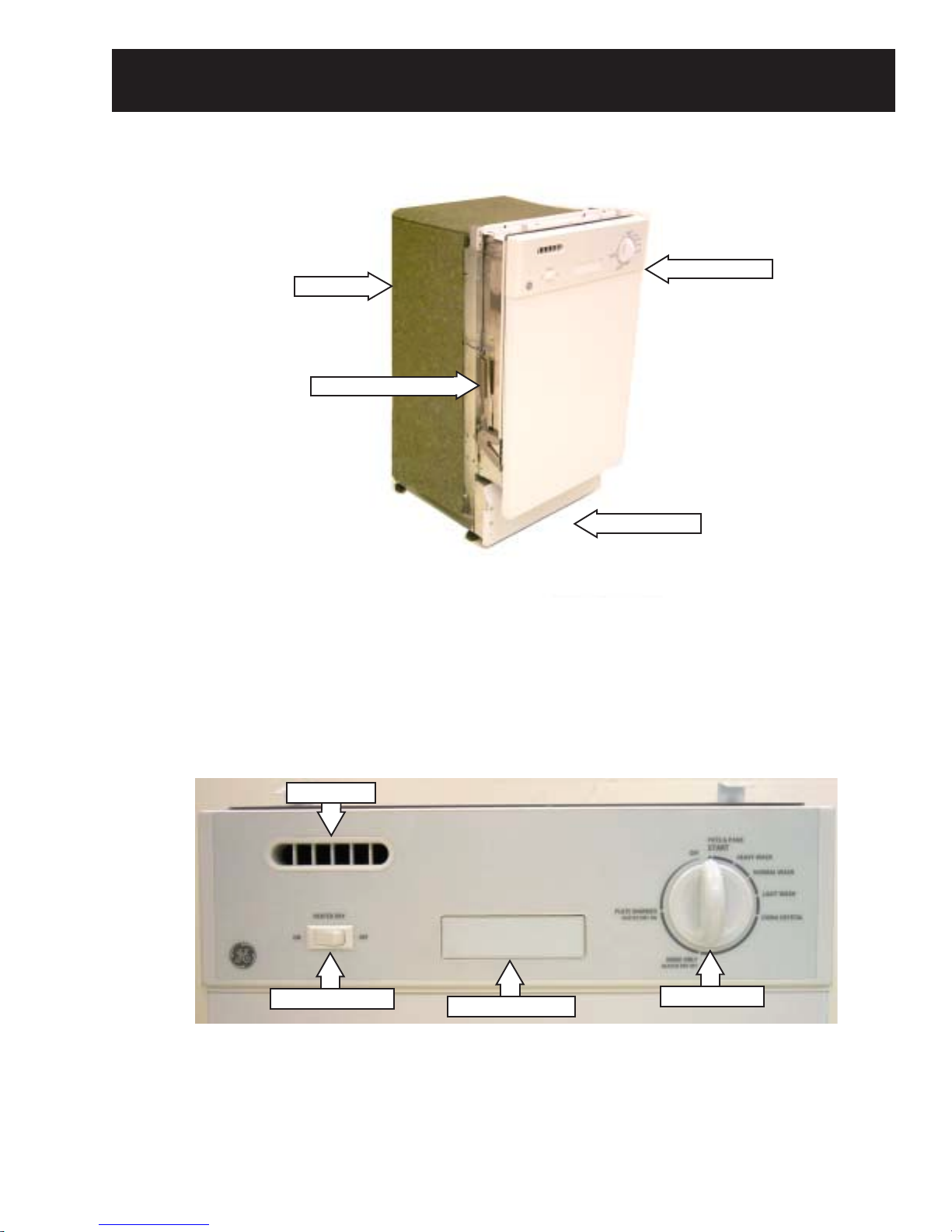
Control Panel Features ..........................................................................................6
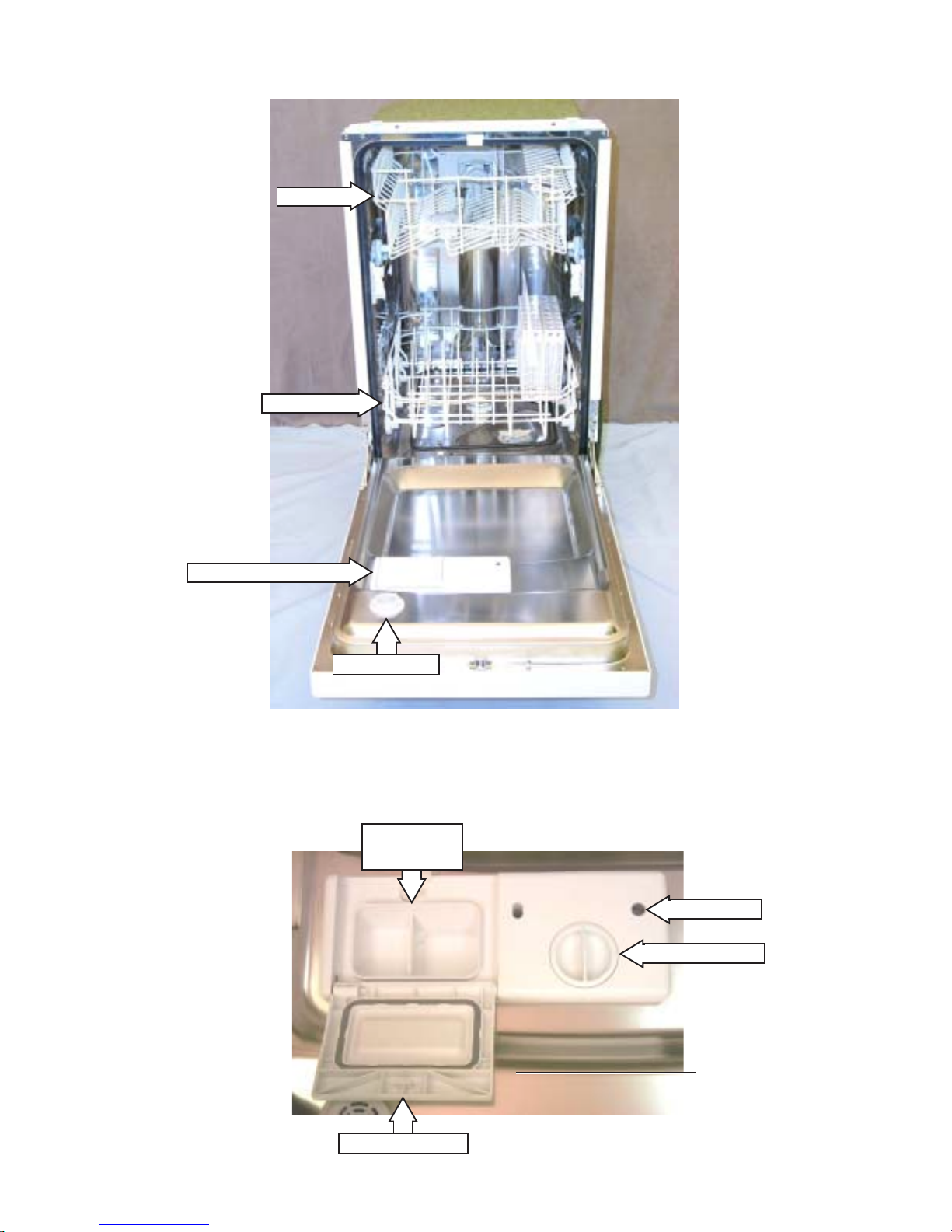
Detergent/Rinse Module .......................................................................................15
Dishwasher Components ................................................................................... 10
Dishwasher Tub Seal .......................................................................................... 19
Door Assembly..................................................................................................... 16
Door Panel ...........................................................................................................14
Door Switch and Latch Assembly ........................................................................ 12
Drain Pump Assembly..........................................................................................23
FillFunnel .............................................................................................................20
Heated Dry Switch................................................................................................ 11
HeatingElement ...................................................................................................19
Illustrated Parts Catalog .......................................................................................40
Introduction............................................................................................................ 4
Motor Pump Assembly ........................................................................................ 24
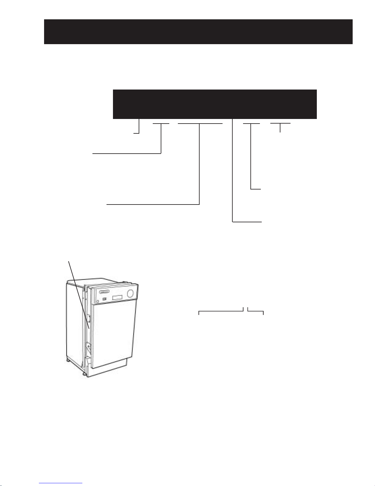
Nomenclature ........................................................................................................ 5
Pressure Switch.................................................................................................. 22
Schematic ............................................................................................................ 38
Specifications .........................................................................................................4
Static Dry System.................................................................................................13
Sump Assembly ...................................................................................................26
Timer ....................................................................................................................10
Troubleshooting .................................................................................................... 28
Warranty...............................................................................................................46
Washability Complaints ........................................................................................37
WaterValve ..........................................................................................................21

– 4 –
Introduction
The new Spacemaker 18" Built-In Dishwasher has a compact size,
allowing the unit to fit in areas as small as 18 inches (45.72 cm) wide,
22 inches (55.88 cm) long, and 34 inches (86.36 cm) high. It is
compact in size, yet still delivers the performance of larger units. With
a low power usage, this product model meets ENERGY STAR®
guidelines for energy efficiency.
The Spacemaker 18" Built-In Dishwasher has two wash levels, a
POTS & PANS cycle, HEAVY WASH cycle, NORMALWASH cycle,
LIGHT WASH cycle, CHINACRYSTALcycle, RINSE ONLY cycle, and a
PLATE WARMER (HEATED DRY ON) option.
Electrical
Rating 120 Volts, 60 Hz ±10%
Separate Circuit 4.5 to 5.5 Amps
Motor (HP) 1/5
Motor (Amps) 1 ±10%
Heater Wattage – Wash/Dry 465 ±10%
Total Amps (Load Rated) 5 ±10%
Component Resistance (OHMS)
Timer Motor 1460 ±10%
Heating Element 31 ±5%
Pump Motor Windings
Drain
Wash (Blue to Red)
27 ±10%
47 ±10%
Run Windings – Main
(Blue to Black) 22 ±10%
Water Valve Solenoid 1140 ±5%
Total Amps (Load Rated) 5 ±10%
Water Supply
Suggested Minimum
Incoming Water Temperature 120 °F to 150 °F
(49 °C to 66 °C)
Sump Water Temperature
With Outer Door In Place 145 °F ±5 °F
(63 °C ±3 °C)
Water Charge 2.54 to 3.27 Quarts
(2.4 to 3.1 Liters)
Pressure (PSI) 20 Min./120 Max.
Connection (NPT) 3/8 In. (0.95 cm)
Consumption (Total) 4.7 to 6.1 Gallons
(17.8 to 23.1 Liters)
Water Valve Flow Rate
(GPM) 1.8 ±14%
(6.81 LPM ±14%)
Water Circulation Rate (GPM) 10 ±10%
(37.85 LPM ±10%)
Water Fill Time (Seconds) 30 (±1)
Specifications

– 5 –
Model Designator
Designates features – the higher
the number, the more features.
Nomenclature
The letter designating
theyearrepeatsevery
12 years.
Example:
T = 1974
T = 1986
T = 1998
G S M 1 8 0 0 J 0 0 W W
Brand
P = Profile
E = General Electric - NATM
G = General Electric
Product Type
CD - Counter Top DW = Dishwasher
SD = Standard SC = Convertible
SM = Spacemaker SS = Compact (18 in.)
RF = Retrofit HD = Home Depot Derivative
Exterior Color
BB = Black
CC = Bisque
SS = Stainless Steel
WW = White
Model Year Designator
Engineering Model Suffix
Nomenclature
Model Number
The serial plate of your
dishwasher is located on the
tub wall, just outside the
door.
The service information sheet is
located under the control panel.
Serial Number
The first two characters of the serial number identify
the month and year of manufacture.
Example: AA123456S=January, 2001
A-JAN 2005 - H
D - FEB 2004 - G
F - MAR 2003 - F
G - APR 2002 - D
H- MAY 2001 - A
L - JUN 2000 - Z
M - JUL 1999 - V
R - AUG 1998 - T
S - SEP 1997 - S
T - OCT 1996 - R
V - NOV 1995 - M
Z - DEC 1994 - L

– 6 –
Control Panel Features
HEATED
DRY
Switch:
Control Timer:
POTS & PANS
HEAVYWASH
NORMALWASH
LIGHT WASH
CHINACRYSTAL
RINSEONLY For rinsing partial loads that will be washed later. Do not use detergent with this cycle.
Thiscycle is for everyday dishes and glassware.
This cycle is specifically designed for lightly soiled china and crystal.
This cycle is for medium-soiled dishes and glassware.
This cycle is for heavily soiled dishes and glassware.
Thiscycle isspecificallydesigned forheavy soiled cookwarewith dried-onor baked-on
soils. This cycle may not remove burned-on foods. Everyday dishes are safe to be used
in this cycle.
PLATE WARMER
HEATEDDRYON Do not use detergent with this cycle.
Turnsthe heatingelement on forfast drying.ON
OFF Turns the heating element off. Dishes dry naturally and energy is saved. For faster air
dry, you can prop the door open during the PLATE WARMER cycle.
START Close the dishwasher door and turn the control timer knob to the desired setting.
Water fill begins and approximately 30 seconds later, the wash action begins.
Door Latch
Switch: Automaticallyshuts off thedishwasher wheneverthedishwasher doorisopened. The
dishwasher will not resume operation until the door is closed.
Heated Dry Switch Door Latch Switch Control Timer

– 7 –
Front View
Component Locator Views
Control Panel View
Door Latch Switch
StaticVent
Control Timer
Heated Dry Switch
Door Tension Spring
Insulation ControlPanel
Access Panel

– 8 –
Interior View (With Racks)
Detergent/Rinse Module Compartment View
StaticDryVent
Detergent/Rinse Module
Bottom Rack
Top Rack
Detergent
Compartment
CompartmentLid
Sight Glass
RinseAgentCap

– 9 –
Interior View of Basin (With Racks Removed)
Bottom View (Looking Up)
Right Side View (Insulation Removed)
Fill Funnel
Pressure
SwitchHose
Fill Hose
HeatingElement
SprayArm
Filter Assembly
Micro-filter
Clamp Nut
Sump
DrainPump
Capacitor
MotorPump
Assembly

– 10 –
Dishwasher Components
Throughoutthismanual,featuresandappearance
may vary from your model.
3. Remove the top screw and mark the hole
threads with a felt-tip marker.
4. Remove the bottom screw and mark the hole
threads with a felt-tip marker.
5. Open the dishwasher door.
6. Remove the 6 screws that connect the control
panel cover to the dishwasher door.
Mark the inside of
thehole threads with
a felt-tip marker.
7. Close the dishwasher door.
Timer
WARNING: Always turn off the electric power
supply before servicing any electrical component,
making ohmmeter checks, or replacing any parts.
Note: All voltage checks should be made with a
voltmeter having a full scale range of 130 volts or
higher.After service is completed, be sure all
safety grounding circuits are complete, all
electrical connections are secure, and all access
panels are in place.
The timer allows the user to select the various
cleaning cycles of the dishwasher. The timer
controls all stages of each cycle.All electrical
functions can be traced on the charts and
diagrams provided in this service manual.
Removal and Installation
1. Disconnect the electrical supply from the
dishwasher.
2. Remove the control timer knob from the
control panel cover.
Control Timer Knob

– 11 –
8. Release the door latch and allow the control
panel cover to hang against the dishwasher
door.
9. Disconnect the ground wire from the timer.
10. Disconnect the connectors. (Refer to mini-
manual or chart on page 38 for reconnection.)
Note: When installing the timer, it is important to
align the threaded holes (A) and (B), marked in
step 3, with holes (A) and (B) in the control panel
B
A
Heated Dry Switch
The heated dry switch is used to turn the heating
element ON or OFF. For faster drying, the switch
is set to ON, and the heating element will energize
following the rinse cycle. When the switch is set
to OFF, dishes dry naturally, and energy is saved.
The heated dry switch is located on the left-hand
side of the control panel.
Removal and Installation
1. Disconnect the electrical supply from the
dishwasher.
2. Open the dishwasher door.
3. Remove the 6 screws that connect the control
panel cover to the dishwasher door. (See
Timer, step 6.)
4. Close the dishwasher door.
5. Release the door latch and allow the control
panel cover to hang against the dishwasher
door.
6. Press in the heated dry switch tabs and pull
the switch out from the front of the control
panel.
Timer
ControlPanel
Threaded Hole (A)
ThreadedHole(B)
Alignthethreaded
holes marked in step
3 with the holes in
thecontrol panel.
White Multi-Pin Connector

– 12 –
7. Remove the 4 screws that connect the door
switch mounting bracket to the control panel
cover.
7. Disconnect the 2 wire terminals from the
heated dry switch and remove the switch.
8. Reverse the above procedure to install.
8. Pull the door switch assembly down far
enough so that the door latch cup clears the
door latch mounting bracket.
Assembly
Door Switch and Latch Assembly
The latch and switch assembly are located on
the door assembly behind the control panel cover.
The dishwasher will not operate until the door is
closed, the latch engages the door catch (holding
the door firmly against the seal), and the normally
open contacts of the double-pole, single-throw
door safety switch are closed.
Removal and Installation
1. Disconnect the electrical supply from the
dishwasher.
2. Open the dishwasher door.
3. Remove the 6 screws that connect the control
panel cover to the dishwasher door. (See
Timer, step 6.)
4. Close the dishwasher door.
5. Release the door latch and allow the control
panel cover to hang against the dishwasher
door.
Note: There are six terminals on the door
switch. The top two terminals (1) and (2) are not
used. The middle two terminals are marked (3)
and (4). The bottom two terminals are marked (5)
and (6).
6. Tag and disconnect the 4 wire terminals from
the door switch.
Pull
Bracket
Cup

– 13 –
4. Remove the static vent channel cover and
assembly as shown below. Inspect the cover
for hard water/lime deposits or debris and
clean if necessary.
5. Inspect the o-ring. If the o-ring shows obvious
signs of wear or damage, replace the channel
assembly.
6. Inspect the gasket on the channel assembly.
If the gasket shows obvious signs of wear or
damage, replace the channel assembly.
Channel
O-Ring
Gasket
10. Inspect the door latch spring. Make sure the
door latch flap fits properly in the door latch
flap hole. If the spring is misaligned, broken,
or missing, insert a new spring in the spring
post holes.
9. Remove the door switch from the door switch
mounting bracket.
11. Reverse the above procedure to install.
Bracket
Static Dry System
The static dry system operates through a vent
located in the control panel. The vent allows hot
air to exit the dishwasher tub and gradually
remove moisture.
Removal
1. Open the dishwasher door.
2. Remove the 6 screws that connect the control
panel cover to the dishwasher door. (See
Timer, step 6.)
3. Release the door latch and allow the control
panel cover to hang against the dishwasher
door.
Switch
Flap
Spring
Cover
(Continued next page)

– 14 –
Door Panel
2. Install the static vent cover to the static vent
channel and position the control panel cover
on the dishwasher door.
Note: Make sure the edge of the control panel
cover is flush with the edge of the door.
3. Align the screw holes on the control panel with
the screw holes on the dishwasher door.
Installation
1. Insert the static vent channel through the
static vent door hole.
Hole
Channel
4. Install the 6 screws that connect the control
panel cover to the dishwasher door.
Cover
Makesure theedge
of the control panel
is flush with the edge
of the door.
Door Panel
The door panel covers the door to the dishwasher
and protects the detergent/rinse module
electronics.
Removal
1. Disconnect power.
2. Open the dishwasher door.
3. Remove the 6 screws and the door panel
from the door assembly. Do not remove the 6
screws that hold the control panel cover to the
door assembly.

– 15 –
This action moves the cover catch (2) and
releases the detergent cover.
When deactivated (3), the lever resets to rest
under the notch in the center of the connecting
rod.
When activated for the second time in a cycle, the
lever lifts the connecting rod by the notch, lifting
the rinse dispenser plunger (4) and releasing the
rinse agent. When deactivated, the lever returns
to its original starting position.
Removal and Replacement
1. Disconnect power.
2. Remove the Door Panel.
3. Remove the foam insulation.
Cover
Detergent/Rinse Module
The detergent rinse module automatically
dispenses both the detergent and the rinse agent
at the appropriate times. The module is activated
twice during a wash cycle.
The first time the module is activated (1), the lever
slides up the right-hand path of the connecting
rod.
1
4
3
2
Insulation
4. Disconnect the 2 terminals from the
detergent/rinse module.
(Continued next page)

– 16 –
9. Remove the Door Panel.
10. Disconnect the 2 terminal lugs from the
Detergent/Rinse Module switch.
5. Remove the 3 screws and top mounting
bracket.
6. Remove the 3 screws and bottom mounting
bracket.
7. Remove the detergent/rinse module from door
assembly.
Door Assembly
Removal and Replacement
1. Disconnect power.
2. Remove the 6 screws that connect the control
panel cover to the dishwasher door. (See
Timer, step 6.)
3. Close the dishwasher door.
4. Release the door latch and allow the control
panel cover to hang against the dishwasher
door.
5. Disconnect the ground wire from the Timer.
6. Disconnect the green and white multi-pin
connectors from the Timer.
7. Disconnect the 4 terminal lugs from the Door
Switch and Latch Assembly.
8. Disconnect the 2 terminal lugs from the
Heated Dry Switch.
Detergent/Rinse Module
Timer
DoorLatch
HeatedDry Switch
Bracket
Bracket

– 17 –
14. Pull the spring and spring bolt key from the
mounting bracket.
15. Lift the bottom of the spring loop from the
hinge arm stud.
16. Open the dishwasher door approximately 30
degrees.
17. Lift the bottom hinge arm up from the bottom
hinge, far enough to expose the hook.
Key
Loop
Stud
11. Remove the bolt, nut, and ground wire from
the door.
12. Pull the wire harness from the door.
Note: There is a door hinge assembly on both
the left and right sides of the dishwasher. Both
door hinge assemblies must be removed in order
to remove the door. The procedure to remove the
right-side door hinge assembly is outlined in steps
13 through 23. The left-side door hinge assembly
is identical.
13. Mark the position of the spring bolt key in the
mounting bracket with a felt-tip marker.
Bracket
Bolt, Nut, and
Ground Wire
Wire Harness
Open
Lift

– 18 –
18. Close the dishwasher door.
Caution: The star washer is easily damaged
during removal and should not be reused. Order
a new set of star washers (part number:
WD01X10254).
19. Remove the star washer from the
dishwasher door hinge.
Hinge
Caution: The
starwasher is
easilydamaged
andshould not
bereused.
21. Repeat steps 3 through 10 to remove the left-
side door hinge assembly.
22. Remove the dishwasher door from the
dishwasher.
23. Reverse the above procedure to install.
20. Remove the hinge pin from the dishwasher
doorhinge.
Pin
Tub Seal
4. Reverse the above procedure to install.
Note: When installing the door, seal make sure it
is seated properly in the pinched metal groove.
Run your finger over the groove to make sure it is
smooth and even for a proper seal.
Bottom Door Seal
The bottom door seal prevents water leakage.
The seal is fitted in a pinched metal groove at the
bottom of the dishwasher door.
Removal and Replacement
1. Remove the Door Panel.
2. Remove the Door Assembly (steps 13
through 22 only).
3. Grab one end of the bottom door seal and peal
it away from the pinched metal groove.
Warning: The pinched metal groove is sharp.
Wear Kevlar gloves when removing or installing
the door seal. Failure to comply may result in
personalinjury.
Pinched Metal
Groove
Hook
Star Washer
Make sure the seal is
properlyseated in the
pinchedmetalgroove.

– 19 –
6. Disconnect the 2 terminal lugs from the
heatingelement.
2 Wire Covers
2 Wire Protectors
2 Strain Reliefs
3. Reverse the above procedure to install.
Note: When installing the tub seal, make sure it
is seated properly in the seal channel. Run your
finger over the seal to make sure it is smooth and
even for a proper seal. Acorrectly installed gasket
will have both ends of the gasket equidistant from
the bottom of the tub.
Tub Seal
Seal Channel
Dishwasher Tub Seal
The dishwasher tub seal prevents water leakage.
The seal is fitted in a seal channel that lines the
rim of the dishwasher tub.
Removal and Replacement
1. Open the dishwasher door.
2. Grab one end of the dishwasher tub seal and
peal it away from the seal channel.
Heating Element
The heating element maintains water temperature
during the wash and rinse cycles and heats the
air during the static dry cycle. (See
Specifications for heating element wattage
ratings.)
To check operation, advance timer to the dry
cycle, set the selector switch for heated dry, close
and latch the dishwasher door.Allow one or two
minutes, open the dishwasher door and note if
heat is present.
Removal and Replacement
1. Disconnect power.
2. Open the dishwasher door.
3. Remove the top and bottom dishwasher
racks.
4. From underneath the dishwasher tub, locate
the wires leading to the heating element.
5. Pull down the nylon covers, rubber wire
Make sure the seal
isseated properlyin
the seal channel.

– 20 –
7. Remove the nut and ground wire.
8. Remove the lock-washer and spacer bracket.
Ground Wire
Spacer Bracket
Lock-
washer
Nut
10. Lift up and remove the heating element from
the dishwasher.
11. Reverse the above procedure to install.
9. Release the 2 heating element clamps.
Turn CCW
Fill Funnel
The fill funnel is mounted on the left side of the
tub. Its purpose is to provide a method of
supplying water for the wash and rinse cycles.
The air gap prevents the siphoning of wash water
from flowing back into the water supply system,
should the water pressure drop to less than
atmospheric pressure. The fill funnel also allows
air into the tub to permit air flow for dish drying.
Removal and Replacement
1. Fold back the insulation surrounding the fill
funnel and air gap assembly.
2. Open the dishwasher door.
3. Rotate the fill funnel cap counterclockwise and
remove it from the fill funnel threads.
Heating Element
Funnel Cap
Threads
Table of contents
Other GE Dishwasher manuals