GE Profile DPGT650GH How to use

– 2 –
IMPORTANT SAFETY NOTICE
The information in this service guide is intended for use by individuals pos-
sessing adequate backgrounds of electrical, electronic, and mechanical expe-
rience. Any attempt to repair a major appliance may result in personal injury
and property damage. The manufacturer or seller cannot be responsible for
the interpretation of this information, nor can it assume any liability in con-
nection with its use.
WARNING
If the information in this manual is not followed exactly, fire or explosion may
result causing property damage, personal injury or death. If you smell gas:
– Do not try to light any appliance.
– Do not touch any electrical switch; do not use any phone in the
building.
– Immediately call the gas supplier from a neighbor’s phone. Follow the
gas supplier’s instructions.
– If you cannot reach the gas supplier, call the fire department.
WARNING
To avoid personal injury, disconnect power before servicing this product. If
electrical power is required for diagnosis or test purposes, disconnect the power
immediately after performing the necessary checks.
RECONNECT ALL GROUNDING DEVICES
If grounding wires, screws, straps, clips, nuts, or washers used to complete a
path to ground are removed for service, they must be returned to their original
position and properly fastened.
GE Consumer & Industrial
Technical Service Guide
Copyright © 2008
All rights reserved. This service guide may not be reproduced in whole or in part in
any form without written permission from the General Electric Company.

– 3 –
Airflow ....................................................................................................................................................................................12
Backsplash...........................................................................................................................................................................17
Belt Switch............................................................................................................................................................................24
Blower Housing..................................................................................................................................................................25
Clean Filter........................................................................................................................................................................... 9
Component Locator Views...........................................................................................................................................13
Component Logic Flow Chart .....................................................................................................................................34
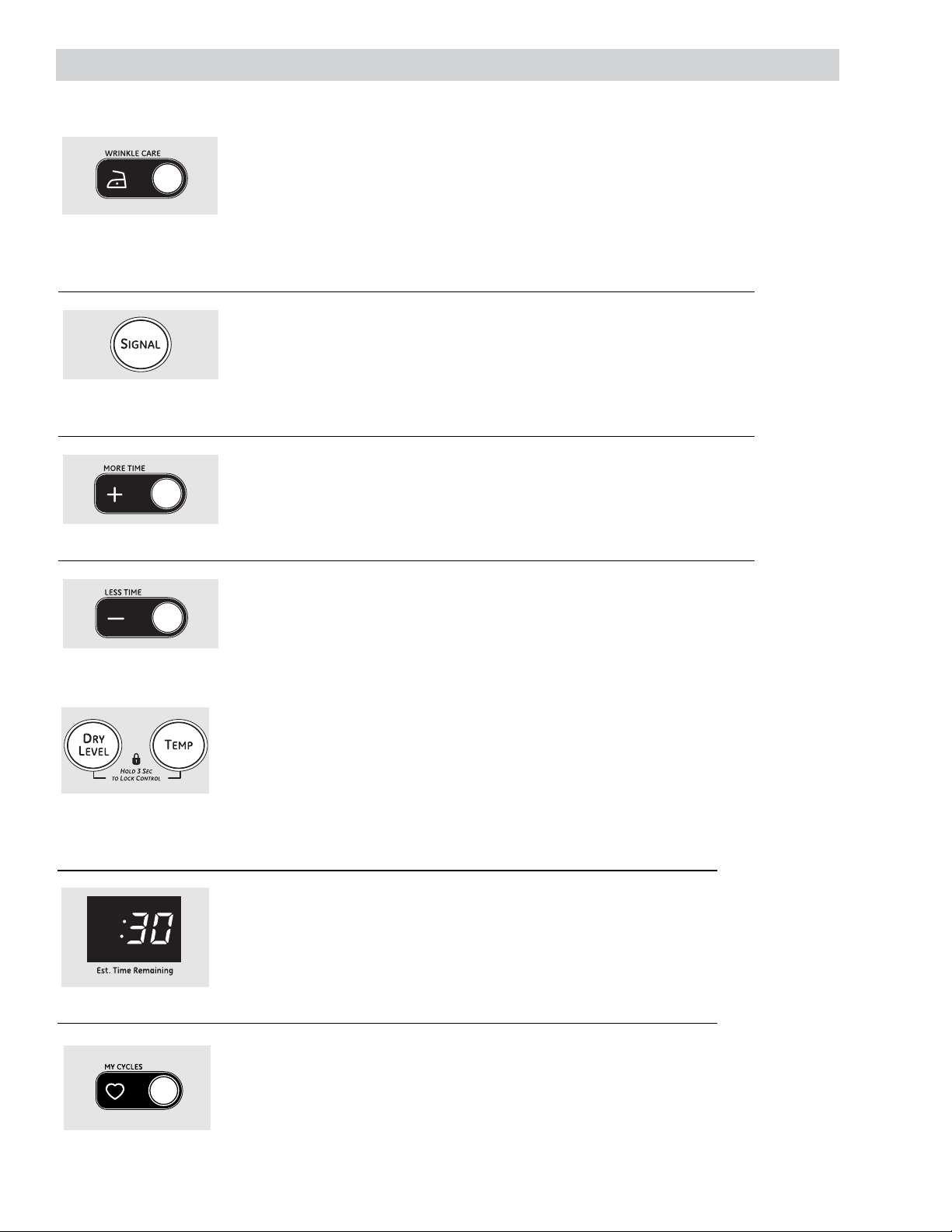
Control Features............................................................................................................................................................... 6
Control System ..................................................................................................................................................................17
Cycle Options...................................................................................................................................................................... 8
Display Assembly .............................................................................................................................................................17
Door Switch ......................................................................................................................................................................... 23
Drive Belt...............................................................................................................................................................................21
Drive Motor..........................................................................................................................................................................24
Drum.......................................................................................................................................................................................22
Drum Light ...........................................................................................................................................................................23
Drum Rollers........................................................................................................................................................................23
Dryer Components...........................................................................................................................................................17
Dryer Features................................................................................................................................................................... 9
Error Codes .......................................................................................................................................................................... 37
Front Panel...........................................................................................................................................................................20
Gas Valve (Gas Models)..................................................................................................................................................30
Heater Assembly (Electric Models)............................................................................................................................26
Hi-Limit Thermostat.........................................................................................................................................................30
Ignitor.....................................................................................................................................................................................32
Ignitor and Flame Detector..........................................................................................................................................32
Inlet Safety Thermostat.................................................................................................................................................28
Inlet Thermistor..................................................................................................................................................................27
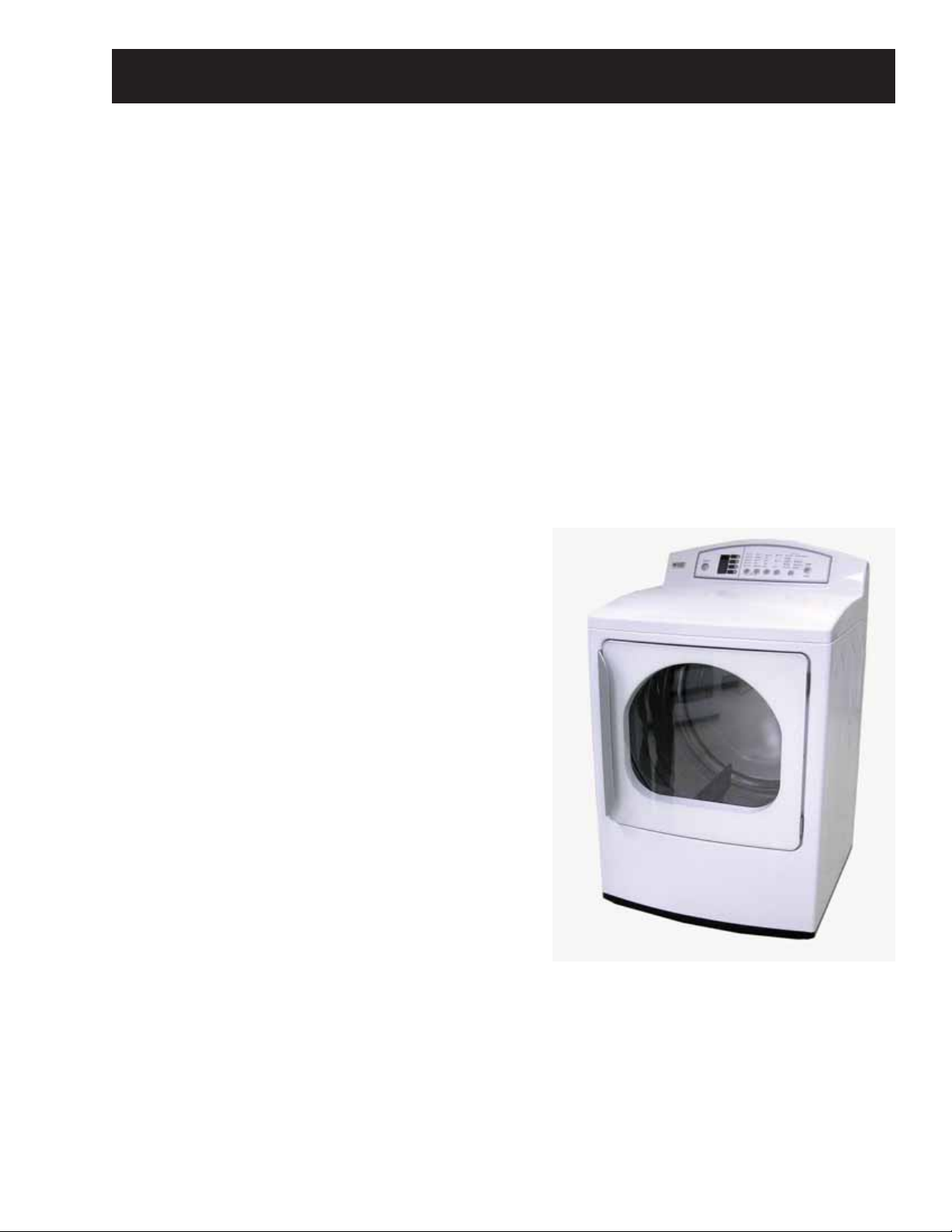
Introduction......................................................................................................................................................................... 5
Main Control Board..........................................................................................................................................................18
Main Control Board and Display Assembly Pin Connectors.........................................................................15
Moisture Sensor.................................................................................................................................................................32
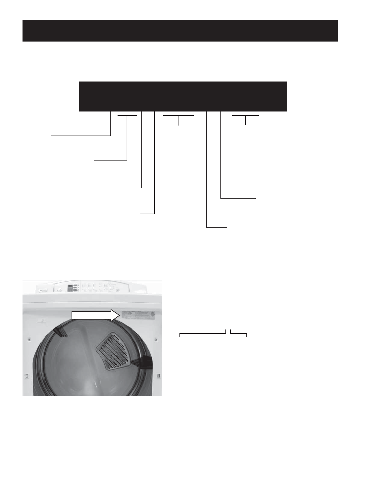
Nomenclature .................................................................................................................................................................... 4
Outlet Thermistor..............................................................................................................................................................29
Outlet Thermostat ............................................................................................................................................................29
Reversing the Door Swing ............................................................................................................................................10
Schematics and Wiring Diagrams............................................................................................................................38
Service Test Mode.............................................................................................................................................................35
Signal (Beeper)....................................................................................................................................................................19
Top Cover..............................................................................................................................................................................19
Top Plate ...............................................................................................................................................................................21
Warranty ..............................................................................................................................................................................40
Table of Contents

– 4 –
Nomenclature
The letter designating
the year repeats every
12 years.
Example:
T - 1974
T - 1986
T - 1998
Serial Number
The first two characters of the serial number
identify the month and year of manufacture.
Example: AR123456S = January, 2008
A- JAN 2008 - R
D - FEB 2007 - M
F - MAR 2006 - L
G - APR 2005 - H
H - MAY 2004 - G
L - JUN 2003 - F
M - JUL 2002 - D
R - AUG 2001 - A
S - SEP 2000 - Z
T - OCT 1999 - V
V - NOV 1998 - T
Z - DEC 1997 - S
The nomenclature tag is located on
the front panel inside the door.
Note: The technical sheet is located
inside the control panel.
Model Number
Capacity/Conf guration
G = Giant
D P G T 6 5 0 G H W W
Brand
D = General Electric
Feature Packages
P = Pedestal
Backsplash Control/Platform
T = Buttons
Color
WW - White
RR - Red
GG - Gold
Model Year
2008
Fuel/Voltage
E = Electric - 220V/208V
60 Hz.
G = Gas - 120V 60Hz.
Nomenclature
Control
Features

– 5 –
Introduction
The GE Profile High-Efficiency Dryer is part of the GE Profile Clothes Care System, utilizing the latest
developments in dryer technology.
The Profile Dryer System utilizes strategically placed sensors. This enables the dryer to respond quickly to
temperature changes and ensures proper air flow to optimize drying effectiveness.
Other features include:
Dual Thermistors - Thermistors are much more sensitive to temperature changes and can relay the
information faster than thermostats. The dryer uses dual thermistors to monitor incoming air temperature,
as well as the air temperature leaving the drum.
Moisture Sensor - The moisture sensor allows the control to monitor the fabric for moisture content and end
the cycle at the desired moisture level. (See Moisture Sensor.)
Plastic Top & Backsplash - The dryer top and backsplash have UV stabilizers to prevent yellowing when
exposed to sunlight.

– 6 –
Throughout this manual, features and appearance may vary from your model.
Control Features
(Continued Next Page)
32
6 5
147
1
2
Power
Press to “wake up” the display. If the display is active, press to put the dryer in the idle mode.
NOTE: Pressing POWER does not disconnect the appliance from the power supply.
Cycles
The cycle controls the length and tumble speed of the drying process. The chart below will help you
match the dry setting with the loads.
Sensor Cycles
COTTONS For cottons and most linens.
MIXED LOAD For loads consisting of cottons and poly-blends.
WRINKLE FREE For wrinkle-free and permanent press items.
ACTIVE WEAR Clothing worn for active sports exercise and some casual wear. Fabrics include new
technology finishes and stretch fibers such as Spandex.
DELICATES For lingerie and special-care fabrics.
ULTRA DELICATES For delicate fabrics.
Manual Dry Cycles
SPEED DRY For small loads that are needed in a hurry, such as sports or school uniforms. Can also be
used if the previous cycle left some items damp, such as collars or waistbands.
DEWRINKLE For removing wrinkles from items that are dry or slightly damp. This cycle is not
recommended for delicate fabrics.
AIR DRY Use this feature to tumble items without heat.
MyCycles
MY CYCLES Press to use, create or modify a custom dry cycle.
___________________________________________________________________________________

– 7 –
Time Dry
Use to set your own dry time. TIME DRY is also recommended for small loads.
To use TIME DRY:
1. Press the TIME DRY button until the amount of time you want is selected.
2. Select the temperature by pressing the TEMP button.
3. Close the door.
4. Press the START/PAUSE button.
Dry Level
The sensor continuously monitors the amount of moisture in the load. When the moisture in your
clothes reaches your selected dry level, the dryer will stop.
VERY DRY Use for heavy fabrics.
MORE DRY Use for heavy or mixed type of fabrics.
NORMAL Use for normal dryness level suitable for most loads. This is the preferred cycle
for energy saving.
LESS DRY Use for lighter fabric (ideal for ironing).
DAMP DRY For leaving items partially damp.
3
4
TEMP
You can change the temperature of your dry cycle.
HIGH For regular to heavy cottons.
MEDIUM HIGH For regular cottons.
MEDIUM For synthetics, blends and items labeled permanent press.
LOW For delicates, synthetics and items labeled Tumble Dry Low.
EXTRA LOW For lingerie and special-care fabrics.
My Cycles
Set up your favorite combination of settings and save them here for one touch recall.
These custom settings can be set while a cycle is in progress.
To store a MY CYCLES combination of settings:
1. Select your drying cycle.
2. Change TEMP and DRY LEVEL settings to fit your needs.
3. Select any drying OPTIONS you want.
4. Press and hold the pad for three seconds to store your selection. A beep will sound
and the pad will light up.
To recall your stored MY CYCLES combination:
Press the MY CYCLES button before drying a load.
To change your stored MY CYCLES combination:
Follow steps 1–4 in “To store a MY CYCLES combination of settings”.
START
Press to start a dry cycle. If the dryer is running, press it once and it will pause the dryer. Press it again
to restart the dryer cycle.
5
6
7

– 8 –
Cycle Options
Note: Not all features are available on all dryer models.
Wrinkle Care
Tumbles the drum without heat for 10
seconds every 5 minutes for up to 3 hours.
The dryer will display a “racetrack” on the
display during the Wrinkle Care phase.
Wrinkle care shuts off automatically when
the door is opened.
Signal
Alerts you that the cycle is complete.
The clothes should be removed when the
beeper goes off so wrinkles don’t set in.
Press SIGNAL to select low or high volume,
or to turn the beeper off.
The beeper will continue to sound every
2 minutes (maximum of 4 times).
MORE TIME
Increases the dry time in 1-minute
increments, up to 99 minutes.
LESS TIME
Decreases the dry time in 1-minute
increments, down to 10 minutes.
Lock
You can lock the controls to prevent any
selections from being made. Or you can lock
the controls after you have started a cycle.
Children cannot accidentally start the dryer
by touching pads with this option selected.
To lock the dryer, press and hold the DRY
LEVEL and TEMP buttons at the same time
for 3 seconds. To unlock the dryer, press and
hold the DRY LEVEL and TEMP buttons for
3 seconds.
When the lock function is enabled, CL will
blink in the display with the estimated time
remaining.
Estimated Time Remaining
Displays the approximate time remaining
until the end of the cycle.
As the cycle begins, you will see an initial
approximate total cycle time in the display.
Then lights will “race” in the display. This
means the dryer is continuously monitoring
the amount of moisture in the load. The lights
will continue until the dryer senses a low level
of moisture in the load. At that point, the
dryer will calculate and display the
approximate time remaining.
_________________________________________________________________________________________
My Cycles
To save a favorite cycle, set the desired
settings and hold down the MY CYCLES
button for 3 seconds. A beep will sound to
indicate the cycle has been saved.
To use your custom cycle, press the MY
CYCLES button before drying a load.
To change the saved cycle, set the
desired settings and hold down the MY
CYCLES button for 3 seconds.

– 9 –
Dryer Features
Changing the Drum Lamp
Before replacing the drum lamp, be sure to unplug the dryer power
cord or disconnect the dryer at the household distribution panel
by removing the fuse or switching off the circuit breaker. The drum
lamp is located at the top left of the door frame.
Remove the screw holding the drum lamp shield in place.1.
Slide the shield up and remove.2.
Remove the bulb and replace with a 15-watt, 120-volt3.
candelabra-base bulb.
Replace the lamp shield and screw.4.
Using the Drying Rack
A handy drying rack may be used for drying delicate items, such
as washable sweaters. Hook the rack over the lint filter so the rack
extends into the dryer drum.
Note:
The drying rack should only be used with the TIME DRY cycle. It•
is also strongly recommended when drying sneakers.
Do not use this drying rack when there are other clothes in the•
dryer.
_________________________________________________________________________________________
Screw
Clean Filter
The Clean Filter light will flash when the dryer is powered up. This is to remind the consumer to clean the lint
filter prior to starting the dryer. The Clean Filter light will stop flashing when the start button is pressed and
cycle started.

– 10 –
Reversing the Door Swing
To reverse the door swing:
Open the door and remove the filler plugs1.
opposite the hinges.
2. With the door completely open, remove the
bottom screw from each hinge on the dryer
face.
3. Insert the screws about halfway into the top
holes, for each hinge, on the opposite side
(where you removed the filler plugs). Apply firm
pressure to get the screws started in the new
holes.
4. Loosen the top screw from each hinge on the
dryer face halfway. With one hand holding the
top of the door and the other hand holding the
bottom, remove the door from the dryer by
lifting it up and out.
5. Remove the screws holding the handle and two
spacers.
Rear of Door
6. Remove the door catch and filler plate. Install
them on opposite sides of the door.
Filler
Plate
Catch
(Continued Next Page)

– 11 –
7. Install the handle on the opposite side of the
door.
Rear of Door
8. Remove the hinges from the door and install
them on the opposite side with the hinge pin
toward the outside of the door.
Opposite Side
of Door
9. Insert the door on the opposite side of the
opening by moving the door in and down until
the top hinge and the bottom hinge are resting
on the top screws inserted in Step 3.
10. Remove the remaining screws from the side of
the opening from which the door was removed.
With these screws, secure each hinge at the
bottom.
11. Tighten the two top screws of each hinge.
Reinsert the plastic plugs on the side from which
the door was removed.

– 12 –
Airf ow
Gas and Electric Models
LINT
FILTER
EXHAUSTAIR
INLET
AIR
AREA

– 13 –
Gas Model
Component Locator Views
(Continued Next Page)
Inlet Thermistor
Drive Motor
Blower Wheel
Combustion Chamber
Drum Roller
Outlet Thermistor (behind frame)
Gas Valve
Ignitor
Flame Sensor Detector
Inlet Safety Thermostat
Hi-Limit Thermostat
Outlet Thermostat (behind frame)
Idler Pulley
Manual Reset

– 14 –
Electric Model
Inlet Thermistor
Heater Housing
Inlet Safety Thermostat
Outlet Thermistor (behind frame)
Drive Motor
Blower Wheel
Hi-Limit Thermostat
Outlet Thermostat (behind frame)
Idler Pulley
Drum Roller

– 15 – (Continued Next Page)
Main Control Board and Display Assembly Pin Connectors
Main Control Board (Gas Model)
Main Control Board (Electric Model)
Flame Detector
Gas Valve Coils
Motor
Door Switch
Glow Bar
Neutral
Moisture Sensor
Outlet Thermistor
Inlet Thermistor
Main Board CN14
Main Board CN11
Main Board CN14
Outlet Thermistor Moisture Sensor
Inlet Thermistor
Main Board CN11
Door Switch Motor
Neutral
Outer Heater Coil
Inner Heater Coil
Power Switch Connection From Display Assm

– 16 –
Display Assembly (Electric and Gas Models)
Power Switch
Main Control Board
Display

– 17 –
Dryer Components
WARNING: Sharp edges may be exposed when
servicing the dryer. Use caution to avoid injury.
Wear Kevlar gloves or equivalent protection.
2. Place a towel over the lid of the dryer to prevent
scratches to the surface. Lift each corner of
the backsplash vertically while pulling back
to disengage the 2 tabs. Roll the backsplash
forward so it rests on top of the dryer.
Backsplash
Removal of the backsplash provides access to the
control system components.
To remove the backsplash:
Remove the 4 Phillips-head screws that hold the1.
backsplash in place.
Tab
Control System
The dryer control system consists of two main
components:
Display assembly•
Main control board•
Caution: To prevent electrostatic discharge from
damaging any electronic components, use an ESD
wristband or touch a grounded metal surface before
servicing.
Display Assembly
The display assembly is attached to the backsplash
as one unit.
To remove the display assembly:
Remove the backsplash. (See1. Backsplash.)
Remove the 4 Phillips-head screws that attach2.
the display assembly to the backsplash.
Tab 3. Lift the display assembly from the backsplash.
Viewed From Rear

– 18 –
Main Control Board
The main control board is enclosed in a protective
box attached to the top panel.
It is necessary to remove the backsplash to access
the main control board's protective box.
To access and remove the main control board:
Remove the backsplash. (See1. Backsplash.)
Remove the 2 Phillips-head screws that hold the2.
main control board box to the top panel.
3. Slide the main control board box toward the rear
of the dryer then lift it up.
4. Press the 3 tabs on the side of the main control
board box and gently pry it open.
Tab
Tab
Tab
5. Disconnect the wiring from the main control
board. Remove the board.
Testing the Main Control Board
Voltage readings from the main control board to the
display assembly measured at CN14 should be as
follows:
With the Unit Plugged Into the Wall
Black to Brown 5 VDC
Black to Red 3 VDC
Black to Orange 0 VDC
Black to Yellow 15 VDC
Black to Green 0 VDC
Black to Blue 0 VDC
CN14
CN11
When the Power Button Is Pressed
Black to Brown 5 VDC
Black to Red 12 VDC
Black to Orange 20 VDC
Black to Yellow 11 VDC
Black to Green 2 VDC
Black to Blue 0 VDC

– 19 –
Top Cover
The top cover is held in place by 2 Phillips-head
screws, located beneath the backsplash, and two
front tabs.
To remove the top cover:
Remove the backsplash. (See1. Backsplash.)
Remove the 2 Phillips-head screws that hold the2.
main control board box in place.
Signal (Beeper)
The beeper is mounted on the main control board,
but it is controlled by the display assembly.
To check the 12 VDC circuit, measure between•
pin 3 (white wire) on the white connector CN11
and pin 8 (pink wire) on the blue connector
CN14. (See Main Control Board and Display
Assembly Pin Connectors.)
CN14
12 11 10 9 8 7 6 54321
CN11
11 10 987654321
3. Remove the 4 Phillips-head screws that hold the
display assembly in place.
4. Remove the 2 Phillips-head screws that hold the
top cover in place.
(Continued Next Page)

– 20 –
Front Panel
WARNING: Sharp edges may be exposed when
servicing the dryer. Use caution to avoid injury
and wear Kevlar gloves and sleeves or equivalent
protection.
To remove the front panel:
Remove the top cover. (See1. Top Cover.)
Open the dryer door and remove the 4 Phillips-2.
head screws from the front panel.
5. Slide the wiring harness guard up and out.
Wiring Harness Guard
Caution: In the following step, to prevent
component or wiring damage, ensure the main
control board box and display assembly are
supported. Do not suspend these components by
their wiring.
6. Carefully place the main control board box and
the display assembly off to the side of the dryer.
7. Lift the top cover vertically and slide it forward
to clear the front tabs.
3. Remove the 2 Phillips-head screws that hold the
front panel to the top plate.
4. Lift and tilt the front panel forward slightly then
disconnect the wiring from the door switch.
Disconnect
Other manuals for Profile DPGT650GH
1
This manual suits for next models
2
Table of contents
Other GE Dryer manuals

GE
GE DNCD450EGBWC User manual

GE
GE DDE7200S User manual

GE
GE Profile DPVH890EJ Operating instructions

GE
GE DBVH512EF Manual

GE
GE Spacemaker DSXH43 Original instructions

GE
GE Spacemaker DSKS433EBWW User manual

GE
GE GTDN500EM Manual

GE
GE DWXR483GG Manual

GE
GE GFDN240 User manual

GE
GE Profile 1496508 User manual
Popular Dryer manuals by other brands

Beko
Beko DRVT 61 W Installation & operating instructions and drying guidance

Electrolux
Electrolux EDV705H3WB user manual

Miele
Miele TCR780WP operating instructions

Hotpoint
Hotpoint Aquarius CTD40 Instructions for installation and use

Asko
Asko TDC operating instructions

Indesit
Indesit IDCE G45X B H PS instruction manual