GE GFDS350 How to use

GE Appliances
General Electric Company
Louisville, Kentucky 40225
31-9209
GFDS350
GFDS355
GFDN240
GFDN245
Technical Service Guide
March 2011
GE Appliances
GE HA Dryer With Mist
A
CTIVE
W
EAR
S
PEED
D
RY
P
AUSE
C
OTTONS
N
ORMAL
/
M
IXED
L
OAD
T
IME
D
RY
S
ENSOR
D
RY
T
IME
D
RY
W
ARM
U
P
A
IR
F
LUFF
D
ELICATES
P
OWER
L
EVEL
T
EMP
S
TART
E
ASY
C
ARE
S
TEAM
R
EFRESH
S
TEAM
D
EWRINKLE
M
Y
C
YCLE
S
IGNAL
L
OCK

– 2 –
GE Appliances
Technical Service Guide
Copyright © 2011
All rights reserved. This service guide may not be reproduced in whole or in part in
any form without written permission from the General Electric Company.
IMPORTANT SAFETY NOTICE
The information in this service guide is intended for use by individuals possessing
adequate backgrounds of electrical, electronic, and mechanical experience. Any
attempt to repair a major appliance may result in personal injury and property
damage. The manufacturer or seller cannot be responsible for the interpretation
of this information, nor can it assume any liability in connection with its use.
WARNING
If the information in this manual is not followed exactly, fire or explosion may result
causing property damage, personal injury or death. If you smell gas:
– Do not try to light any appliance.
– Do not touch any electrical switch; do not use any phone in the building.
– Immediately call the gas supplier from a neighbor’s phone. Follow the
gas supplier’s instructions.
– If you cannot reach the gas supplier, call the fire department.
WARNING
To avoid personal injury, disconnect power before servicing this product. If electrical
power is required for diagnosis or test purposes, disconnect the power immediately
after performing the necessary checks.
RECONNECT ALL GROUNDING DEVICES
If grounding wires, screws, straps, clips, nuts, or washers used to complete a path
to ground are removed for service, they must be returned to their original position
and properly fastened.

– 3 –
Table of Contents
Air Duct Assembly ............................................................................................................................................................29
Airflow ....................................................................................................................................................................................22
Belt Switch............................................................................................................................................................................36
Blower Housing..................................................................................................................................................................37
Burner Assembly and LP Conversion......................................................................................................................38
Component Locator Views...........................................................................................................................................24
Control Board Connector Locator View .................................................................................................................26
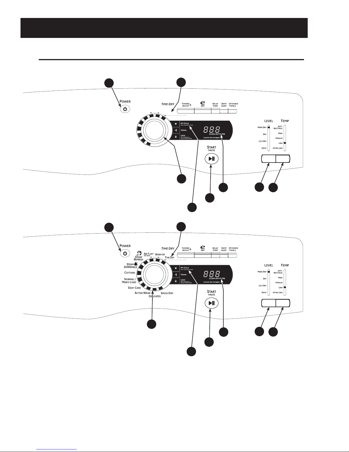
Control Features............................................................................................................................................................... 8
Control Panel.......................................................................................................................................................................27
Cycle Matrix Chart............................................................................................................................................................23
Demo Mode.........................................................................................................................................................................46
Door Switch ......................................................................................................................................................................... 31
Drive Belt...............................................................................................................................................................................32
Drum.......................................................................................................................................................................................33
Drum Light Receptacle...................................................................................................................................................30
Drum Shaft and Bearing................................................................................................................................................33
Drum Slide Assembly......................................................................................................................................................29
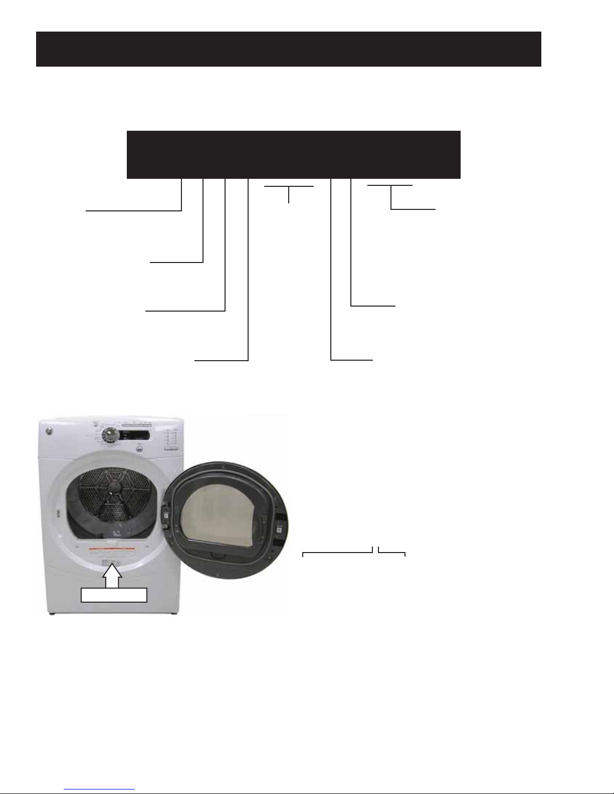
Dryer Components...........................................................................................................................................................27
Electronic Control ............................................................................................................................................................45
Flame Detector ..................................................................................................................................................................40
Front Panel...........................................................................................................................................................................28
Gas Valve..............................................................................................................................................................................39
Gas Valve Coils...................................................................................................................................................................38
Heater Assembly...............................................................................................................................................................37
High Limit Thermostat....................................................................................................................................................44
Idler Assembly....................................................................................................................................................................33
Ignitor.....................................................................................................................................................................................40
Ignitor Circuit Operation................................................................................................................................................41
Inlet Control Thermistor.................................................................................................................................................42
Inlet Safety Thermostat.................................................................................................................................................42
Introduction......................................................................................................................................................................... 5
Moisture Sensor ................................................................................................................................................................31
Motor and Blower Wheel...............................................................................................................................................34
Nomenclature .................................................................................................................................................................... 6
Operation Overview.........................................................................................................................................................21
(Continued Next Page)

– 4 –
Outlet Control Backup Thermostat...........................................................................................................................44
Outlet Control Thermistor .............................................................................................................................................43
Reversing the Door Swing ............................................................................................................................................13
Schematics and Wiring Diagrams............................................................................................................................50
Service Test Mode.............................................................................................................................................................46
Stacking Instructions ......................................................................................................................................................17
Steam Nozzle......................................................................................................................................................................30
Strip Circuit...........................................................................................................................................................................52
Top Panel .............................................................................................................................................................................. 27
Troubleshooting ................................................................................................................................................................46
Warranty ..............................................................................................................................................................................53
Water Inlet Valve ..............................................................................................................................................................34
Water Line Connection .................................................................................................................................................. 7

– 5 –
The two GFDS model dryers incorporate 2 steam
features. The steam cycles are: Steam Refresh and
Steam Derinkle.
These units do not utilize a separate steam generator.
They use a water valve and a steam nozzle that
functions as a “misting” orifice.
It works in conjunction with the
heat generated by the dryer to
de-wrinkle clothing.
• Steam Refresh - Freshens up
to five slightly wrinkled dry
garments, reducing wrinkles
and odors to extend for
another wear.
• Steam Dewrinkle - Helps
remove stubborn wrinkles
from larger loads quickly
and conveniently, even from
clothes left in the dryer from
the day before.
A "Y" connector installed on the
washer's cold water inlet hose
supplies water to the water
valve on the rear of the dryer. An
internal hose carries the water to the misting orifice.
Other Features Include:
• Rotary electronic controls - Simplify cycle
selection with easy-to-use rotary dial controls.
• eDry option - Energy-saving option reduces dry
temperatures on select cycles without sacrificing
performance.
• 5 heat selections - Offer enhanced drying
performance and fabric care.
• My Cycles - Custom cycle that can be set for
specific or frequent needs.
• 24-hour Delay Start - Set the dryer to begin cycles
whenever it's convenient for you.
• Active Wear cycle - Specific settings to take
special care of clothing worn for active sports
Introduction
exercise.
• Speed Dry - Quickly dries items and small
loads for families on the go.
• Up to 90 ft. venting capability - Has long
equivalent ducting
performance for more
flexible installation.
• Deluxe dryer rack - Allows
tumble-free drying of items
like washable sweaters,
sneakers, and stuffed
animals.
• Large 7.5-cubic foot
stainless steel dryer drum.
• Interior Light
• Dual Thermistors -
Thermistors are more
sensitive to temperature
changes and can relay the
information faster than
thermostats. The dryer
utilizes dual thermistors
to monitor incoming air
temperature as well as air temperature
leaving the drum. The sensors work together
with the heater and the blower to provide
consistent, even heat.
• Sensor Dry Plus™ - A moisture sensor allows
the control to monitor the fabric for moisture
content and end the cycle at the desired
moisture level.
• Built-in service test mode. Specific dryer
components can be operated. Error codes are
recorded and accessible on the control panel
display.
• Reversible Door
• ADA Compliant

– 6 –
Nomenclature
The nomenclature tag is located on
the front panel inside the door.
Note: The technical sheet is located
inside the control panel.
Product
W = Washer
D = Dryer
G F D S 3 5 0 E V W W
Brand
P = Profile
G = General Electric
Configuration
T = Top Load
F = Front Load
Key Feature
S = Steam
N = None
Color
WW = White
BB = Black
MV = Metallic Red
MG = Metallic Gold
MS = Metallic Block
Model Year Designator
V = 2011
Fuel
E = Electric
G = Gas
Series
Nomenclature
Serial Number
The first two characters of the serial number
identify the month and year of manufacture.
Example: AV123456S = January, 2011
A- JAN 2011 - V
D - FEB 2010 - T
F - MAR 2009 - S
G - APR 2008 - R
H - MAY 2007 - M
L - JUN 2006 - L
M - JUL 2005 - H
R - AUG 2004 - G
S - SEP 2003 - F
T - OCT 2002 - D
V - NOV 2001 - A
Z - DEC 2000 - Z
The letter designating
the year repeats every
12 years.
Example:
T - 2010
T - 1998
T - 1986

– 7 –
Water Line Connection
Connecting Inlet Hoses.
To produce steam, the dryer must connect to the cold water supply. Since the washer
must also connect to the cold water, a “Y” connector is inserted to allow both inlet hoses
to make that connection at the same time.
NOTE: Use the new inlet hoses provided; never use old hoses.
Connect to Cold Water Supply
1. Turn the cold water faucet off. Remove the washer inlet hose from the washer fill
valve connector (cold).
2. Ensure the rubber flat washer is in place and screw the female coupling of the short
hose onto the washer fill valve connector. Tighten by hand until firmly seated.
3. Attach the female end of the ‘’Y’’ connector to the male coupling of the short hose.
Ensure the rubber flat washer is in place. Tighten by hand until firmly seated.
4. Insert the filter screen in the coupling of the washer’s inlet hose. If a rubber flat
washer is already in place remove it before installing the filter screen. Attach this
coupling to one male end of the ‘’Y’’ connector. Tighten by hand until firmly seated.
5. Ensure the rubber flat washer is in place and attach the dryer’s long inlet hose to the
other male end of the ‘’Y’’ connector. Tighten by hand until firmly seated.
6. Ensure the rubber flat washer is in place and attach the other end of the dryer’s long
inlet hose to the fill valve connector at the bottom of the dryer back panel. Tighten by
hand until firmly seated.
7. Using pliers, tighten all the couplings with an additional two–thirds turn.
NOTE: Do not overtighten. Damage to the couplings may result.
8. Turn the water faucet on.
9. Check for leaks around the ‘’Y’’ connector, faucet and hose couplings.
“Y” Connector

– 8 –
Control Features
(Continued next page)
About the dryer control panel.
You can locate your model number at the top inside of the door opening.
Model GFDN240/245
1
SPEED DRY
NORMAL /
MIXED LOAD
EASY CARE
DELICATES
ACTIVE WEAR
COTTONS
D
EWRINKLE
T
IME
D
RY
A
IR
F
LUFF
NO HEAT
2
3
8
6
45
7
Model GFDS350/355
1
SENSOR DRY
3
45
6
2
7
8

– 9 – (Continued Next Page)
About the dryer control panel.
Power
Press to “wake up” the display. If the display is active, press to put the dryer in the standby mode.
NOTE: Pressing POWER does not disconnect the appliance from the power supply.
Dry Cycles
The dry cycle controls the length and tumble speed of the drying process. The chart below will help you match the dry
setting with the loads.
Sensor Cycles Description
COTTONS For cottons and most linens.
NORMAL/MIXED LOADS For loads consisting of cottons and poly-blends.
EASY CARE For wrinkle-free and permanent press items.
ACTIVE WEAR Clothing worn for active sports exercise and some casual wear. Fabrics include new
technology finishes and stretch fibers such as Spandex.
DELICATES For lingerie and special-care fabrics.
SPEED DRY For small loads that are needed in a hurry, such as sports or school uniforms. Can also be
used if the previous cycle left some items damp, such as collars or waistbands.
1
2
Timed Dry Cycles Description
WARM UP Provides 10 minutes of warming time to warm up clothes.
AIR FLUFF Use this feature to tumble items without heat.
DEWRINKLE
(on some models) For removing wrinkles from items that are dry or slightly damp. This cycle is not
recommended for delicate fabrics.
STEAM REFRESH
(on some models)
For slightly wrinkled dry garments. Significantly reduces wrinkles on up to 5 garments. After
the STEAM REFRESH Cycle, the unit will beep and display “0:00.” If the unit is not turned off
or if the door is not opened, the dryer will continue to tumble for 30 minutes. At the end of 30
minutes, it will display “0:00” and the cycle will be complete.
Note: A single extremely light fabric item may need to have an additional item included in the
STEAM REFRESH cycle to achieve optimum results.
STEAM DEWRINKLE
(on some models) For use with larger loads than STEAM REFRESH. Ideal for loads left in dryer for an extended
time.
My Cycle Description
MY CYCLE Press to use, create or modify custom dry cycles. (See page 8 for more details)
Timed Dry
Use to set your own dry time. TIMED DRY is also recommended for small loads
To use TIMED DRY:
1. Turn dry cycle dial to TIMED DRY.
2. Increase the drying time by pressing the TIMEDRY ADJUST +button.
Note: This button only increases the time. When max time is reached, pressing the button again will reset the counter to
the lowest setting.
3. Select the TEMP.
4. Close the door.
5. Press Start
3
GEAppliances.com

– 10 – (Continued Next Page)
ANTI-BACTERIAL This option may only be used with COTTONS or NORMAL/MIXED LOAD cycles. This option reduces
(on some models) certain types of bacteria by 99.9%, including: Staphylococcus aureus, Pseu-
domonas aeruginosa and Klebsiella pneumoniae*. The anti-bacterial process occurs when high heat
is used during a portion of this drying cycle.
NOTE: Do not use this cycle on delicate fabrics.
* The Anti-Bacterial Cycle is Certified by NSF International (formerly National Sanitation Foundation) to
NSF Protocol P154 Sanitization Performance of Residential Clothes Dryers.
HIGH For regular to heavy cottons.
MEDIUM For synthetics, blends and items labeled permanent press.
LOW For delicates, synthetics and items labeled Tumble Dry Low.
EXTRA LOW For lingerie and special-care fabrics.
4Sensor Dry “Level”
The sensor continuously monitors the amount of moisture in the load. When the moisture in your clothes reaches your
selected dry level, the dryer will stop.
Note: Sensor dry “LEVEL” only works for COTTONS, NORMAL/MIXED LOAD, ACTIVE WEAR, DELICATES, and SPEED DRY.
5Dry “Temp”
You can change the temperature of your dry cycle.
6START
Press to start a dry cycle. If the dryer is running, press it once and it will pause the dryer.
Press it again to resume the dry cycle.
My Cycle
Set up your favorite combination of settings and save them here for one touch recall.
These custom settings can be set while a cycle is in progress.
To store a MY CYCLE combination of settings:
1. Select your drying cycle.
2. Change DRY “TEMP”, and SENSOR DRY “LEVEL” settings to fit your needs.
3. Select any drying OPTIONS you want.
4. Press and hold the pad for three seconds to store your selection. A beep will sound and the pad will light
up.
To recall your stored MY CYCLE combination:
Press the MY CYCLE button before drying a load.
To change your stored MY CYCLE combination:
Follow steps 1–4 in “To store a MY CYCLE combination of settings”.
8“CLEAN LINT FILTER” (message)
(This message represents only a reminder and does not always appear when filter needs cleaning. The filter should be
cleaned after every drying cycle is complete.)
This message will disappear after the START button is pressed. Even though you may have already cleaned the filter
(before or after the POWER button has been pressed), the “CLEAN LINT FILTER” message will still be displayed until the
START button is activated.
7
About the dryer control panel. GEAppliances.com

– 11 –
About cycle options.
NOTE: Not all features are available on all dryer models. GEAppliances.com
Extended Tumble
Minimizes wrinkles by adding approximately
60 minutes of no-heat tumbling after clothes
are dry. The beeper will sound every two
minutes as a reminder to remove the clothes.
The ESTIMATED TIME REMAINING display will
show 00.
The Extended Tumble time does not get
added to the cycle time on the display
Damp Alert
This option causes the dryer to beep when
clothes have dried to a damp level. Remove
items that you wish to hang dry. The
DAMP ALERT will only beep when this option
is selected.
Removing clothes and hanging them when
they are damp can reduce the need to iron
some items.
Delay Start
Use to delay the start of your dryer.
1. Choose your dry cycle and any options.
2. Press DELAY START. You can increase
the delay time in 1 hour increments using
the DELAY START button.
3. Press the START pad to start
the countdown.
NOTES:
If the door is opened while the dryer is
in DELAY START, the countdown time
will not restart unless the door is closed
and START has been pressed again.
e-DRY
Reduces the total energy consumption of
specific dryer cycles by adjusting certain
heat settings.
Note: Cycle times will change when e-DRY is
selected.
This feature can be used with DELICATES,
ACTIVE WEAR, EASY CARE, NORMAL/MIXED
LOADS and COTTONS.
Signal
Alerts you that the cycle is complete.
The beeper will continue to sound every
minute for the next 5 minutes, until the
clothes have been removed. The clothes
should be removed when the beeper goes
off so wrinkles don’t set in.
Press SIGNAL to select low, medium or high
volume, or to turn the beeper off.
(Continued Next Page)

– 12 –

– 13 – (Continued Next Page)
Reversing the door swing. GEAppliances.com
IMPORTANT NOTES:
Read the instructions all the way
through before starting.
Handle parts carefully to avoid
scratching paint.
Set screws down by their related parts
to avoid using them in the wrong places.
Provide a non-scratching work surface
for the door.
Normal completion time to reverse
the door swing is 30–60 minutes.
IMPORTANT: Once you begin, do not move
the cabinet until door-swing reversal is
completed.
These instructions are for changing
the hinges from the right side to the left
side³if you ever want to switch them
back to the right side, follow these same
instructions and reverse all references
to the left and right.
TOOLS YOU WILL NEED
Adjustable Crescent Wrench
Phillips Head Screwdriver
Putty Knife or
Thin-Blade
Screwdriver
DOOR PARTS
Hinge
Cover
Plastic Cover
STEP-BY-STEP INSTRUCTIONS
3 - # 8 Screws
(door asm and front panel)
8 - # 8 Screws
(inner door, outer ring & hinge cover)
4 - # 8 Screws
(strike plate)
6 - # 8 Machine Screws
(inner door & hinge)
7 - Beauty Buttons
Hinge Assembly
Before You Start
1. Unplug the dryer from its electrical outlet.
Reversing the Door Swing

– 14 – (Continued Next Page)
Reversing the door swing.
STEP-BY-STEP INSTRUCTIONS (cont.)
Remove Door Assembly
2. Open the door to approximately 130 degrees.
3. Remove the 2 screws starting from the bottom to the top. Make sure the door
is supported while removing the screws.
4. Loosen the top screw as shown. Unhook the door by lifting and pulling.
5. Place the door on a soft protected flat surface so the inner door faces upward (door
resting on handle side). Remove the 8 tapping screws located around the perimeter of
the door outlining the gasket. Remove the 6 machine screws. Using a putty knife or any
other flat tool, remove the 2beauty buttons and install them on the opposite side.
Remove
Top Screw
8-#8 Tapping Screws
6-# 8 Machine Tapping Screws
4 Beauty Buttons
Outer Door Assembly
Hinge Assembly Hinge Cover
Remove Hinge and Cover
IMPORTANT: Note the location of the hinge (left or right) before removing.
6. With the screws removed, turn the door over and separate the outer door
assembly and hinge cover of the door from the door frame and set aside.

– 15 – (Continued Next Page)
GEAppliances.com
STEP-BY-STEP INSTRUCTIONS (cont.)
Reinstall Hinge Assembly
7. Install the hinge assembly in the opposite side of the door as shown. Push the
hinge assembly in place until the hinge holes align with the door holes.
8. Hold the hinge and door on their side with one hand and fasten the 6
machine screws as shown.
Reinstall Hinge Cover
9. Insert the hinge cover. Align the hinge cover holes with the holes in the door.
10. Secure the hinge cover with 2 taping screws.
Machine
screws
Hinge
Cover
Tapping
Screws

– 16 –
STEP-BY-STEP INSTRUCTIONS (cont.)
Reassemble Door Assembly
IMPORTANT: Make sure there is no dirt or any other foreign material in between the
window panes.
11. Place the plastic outer door onto the inner door. Make sure that the handle part of
the outer door is opposite the hinge as shown.
12. Turn the door over and fasten the outer door to the inner door using the 6 tapping
screws.
Reversing the door swing.
Move Strike Bracket
13. Using a putty knife or any other flat tool, remove the 3 beauty buttons located on the
dryer where the door will be installed and install them on the opposite side.
14. Switch the strike bracket and its cover to the opposite side by removing the screws.
Reinstall both on the opposite side.
Beauty Buttons
Tapping
Screws
Reinstall Door Assembly
15. The door is now ready to be installed on the dryer. To ease this step,
the hinge has keyholes that allow a partially fastened screw to be used
as a hook.
Partially fasten a screw to the uppermost screw hole. Hook the door on the partially
fastened screw.
Fasten the hinge by installing the other 2 screws and tightening the partially
fastened screw above.
Partially
Inserted
Screw
Tighten All
Screws
Inner Door
Outer Door

– 17 –
Stacking. GEAppliances.com
BEFORE YOU BEGIN
Read these instructions completely and carefully.
IMPORTANT: Save these instructions for local
electrical inspector’s use.
IMPORTANT: Observe all governing codes and
ordinances.
Note to Installer – Be sure to leave these
instructions with the Consumer.
Note to Consumer – Keep these instructions
for future reference.
Installation must be performed by a qualified
installer.
Proper installation is the responsibility
of the installer.
FOR YOUR SAFETY
WARNING!
Electric Shock Hazard. Disconnect power before
installing. Failure to do so could result in serious
injury or death.
Potential Personal Injury. When stacking the
dryer, more than two people are recommended
to lift the dryer into position because of its
weight and size. Failure to do so could result in
personal injury or death.
When stacking the dryer,
avoid tipping and
rupture of utility services. Dryer must be
securely attached to the washer. DO NOT place
the washer on top of the dryer. Failure to do so
could result in personal injury/death or property
damage.
Mobile Home or Manufactured Home Installation
– Stacking of a gas dryer is not permitted in a
mobile home or manufactured home.
MINIMUM CLEARANCE OTHER THAN ALCOVE OR CLOSET
INSTALLATION
Minimum clearance to combustible surfaces
and for air opening are: 0sboth sides, 1sfront, and
3srear. Consideration must be given to provide
adequate clearance for installation and service.
ALCOVE OR CLOSET INSTALLATION
If your dryer is approved for installation
in an alcove or closet, it will be stated on
a label on the dryer back.
The dryer MUST be vented to the outdoors. Refer
to dryer Installation Instructions for details.
Minimum clearance between dryer cabinet and
adjacent walls or other surfaces is:
0seither side
3sfront
4srear
Minimum vertical space from floor to overhead
cabinets, ceiling, etc. is 43swithout pedestal,
55swith pedestal and 84sstacked.
Closet doors must be louvered or otherwise
ventilated and must contain a minimum
of 60 square inches of open area equally
distributed. If the closet contains both a washer
and a dryer, doors must contain a minimum
of 120 square inches of open area equally
distributed.
Stacking Instructions
(Continued Next Page)

– 18 –
Stacking.
KIT CONTENTS (optional kit GE FL STACK)
Right Hand Bracket
Left Hand Bracket
4 Rubber Pads 4 #12 x 1” Screws
4 #8 x 1/2” Screws
TOOLS YOU WILL NEED
Phillips Screwdriver
Open-Ended Wrench
Pliers Gloves
Level
INSTALLATION PREPARATION
Remove the packaging.
Flatten the product carton to use as a pad
to lay the dryer down on its side. Continue using
the carton to protect the finished floor in front of
the installation location.
(Continued Next Page)

– 19 –
1. Remove the Dryer
Leveling Legs
A. Carefully lay the dryer on its side.
Use the packing material so you
don’t scratch the finish on the dryer.
B. Use an open-end wrench or pliers
to remove the dryer leveling legs.
INSTALLING THE STACK BRACKET KIT
Back out and remove
all 4 leveling legs
2. Install Rubber Pads
to Dryer Base
Locate the 4 rubber pads in the parts
package. Remove the adhesive backing
and firmly place over on the bracket
where you removed the leveling legs.
3. Install Bracket
to Dryer
A. Align the holes in the left bracket
with the holes in the bottom left
corner of the dryer. Use a Phillips
screwdriver to install the 2 #12 x 1s
tapping screws.
B. Repeat the above step with the right
bracket on the bottom right corner
of the dryer.
C. Set the dryer upright.
NOTE: Make sure to set the dryer
on a piece of packing material so
the brackets that are attached to
the bottom of the dryer do not damage
the floor.
GEAppliances.com
(Continued Next Page)

– 20 –
Stacking.
4. Prepare the Washer
and Dryer
A. Place the washer in the approximate
location.
B. Make sure the washer is level.
Refer to washer Installation
Instructions for details.
C. Remove the back portion of
the control panel by removing
the 3 screws.
D. Reverse dryer door swing if desired.
See dryer Installation Instructions
for details.
NOTE: The washer door swing is not
reversible.
INSTALLING THE STACK BRACKET KIT (cont.)
5. Install Dryer and Bracket
on Washer
A. Lift the dryer on top of the washer.
Be careful not to scratch the top
of the washer with the brackets.
Protect the washer control panel
with cardboard or other protection.
Be sure to lift the dryer high enough
to clear the washer control panel.
WARNING!
Potential Personal Injury. More than
two people are recommended to lift
the dryer into position because of its
weight and size. Failure to do so could
result in personal injury or death.
B. Align the holes in the bracket
with the holes in the back of
the washer. Using a Phillips
screwdriver, attach the 2 #8 x 1/2s
tapping screws. Repeat on both
sides of the washer.
6. Finalize the Installation
A. Refer to the washer Installation
Instructions to complete the washer
installation.
B. Refer to the dryer Installation
Instructions to complete the dryer
installation.
C. Carefully slide or walk the stacked
washer and dryer into place. Use
felt pads or other sliding device
to assist moving and to protect
flooring.
WARNING!
Potential Personal Injury. Do not push
on the dryer once installed to top of
the washer. Pushing on the dryer may
result in pinched fingers.
Place
hands
here
Place
hands
here
This manual suits for next models
3
Table of contents
Other GE Dryer manuals

GE
GE PCKS443EBWW User manual

GE
GE DNCD450GG0WC User manual

GE
GE DCCB330EDKC Manual

GE
GE GE Profile Prodigy DPSR405EAAA User manual

GE
GE GTDP180ED4WW User manual

GE
GE Profile DNSB514 User manual

GE
GE DBSR453 User manual

GE
GE DBXR453 User manual

GE
GE GFDN240GLWW User manual

GE
GE Spacemaker DDP1270G Installation instructions