GE GECLPS3-2 User manual

Tetra®LED Control Module
(GECLPS3-2)
GE
Lighting Solutions
Installation Guide
imagination at work
24
Volt
Save These Instructions
Use only in the manner intended by the manufacturer.
If you have any questions, contact the manufacturer.
WARNING/AVERTISSEMENT
RISK OF ELECTRIC SHOCK
• Disconnect power at fuse box or circuit breaker before
servicing or installing product.
• Properly ground Tetra®power supply.
RISK OF FIRE
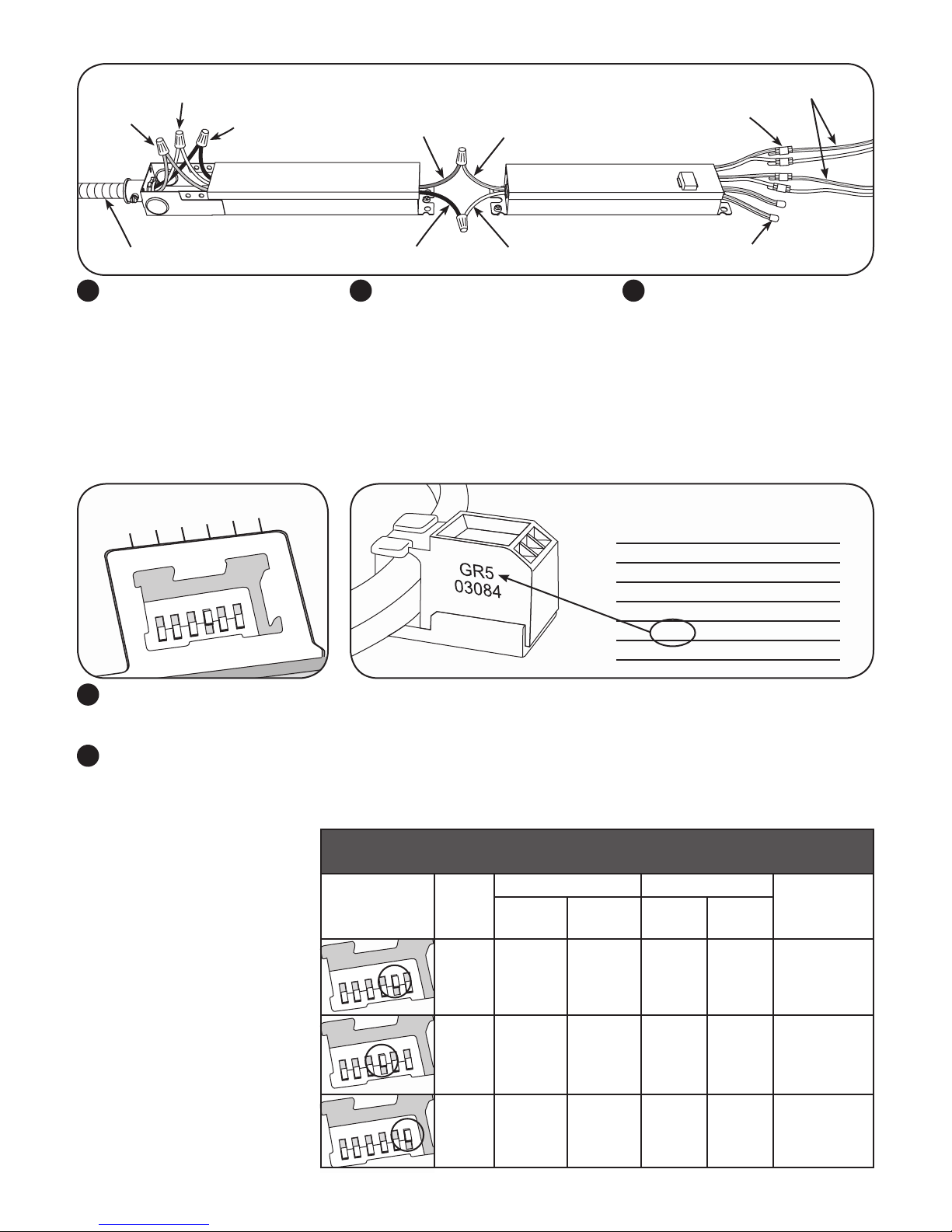
• Use only Tetra®supply wire to make connection from
Tetra®power supply to Tetra®LED strip.
• Use only approved wire for input/output connection.
Minimum size 18 AWG (0.82 mm2)
• Follow all local codes.
RISQUES DE DÉCHARGES ÉLECTRIQUES
• Coupez l’alimentation électrique à la boîte de fusibles ou au disjoncteur avant
l’entretien ou l’installation du produit.
• Assurez-vous de correctement mettre à terre l’alimentation électrique Tetra®.
RISQUES D’INCENDIE
• N’utilisez que le l d’approvisionnement Tetra®pour faire la connexion entre
l’alimentation Tetra®et la bande DEL Tetra®.
• N’utilisez que des ls approuvés pour les entrées/sorties de connexion. Taille
minimum 18 AWG (0.82 mm2).
• Respectez tous les codes locaux.
CAUTION/ATTENTION
RISK OF INJURY
• While performing installations described, gloves, safety glasses
or goggles should be worn.
RISQUE DE BLESSURE
• Lors de l’exécution des installations décrites, des gants, des lunettes de
sécurité ou des lunettes de protection doivent être portées.
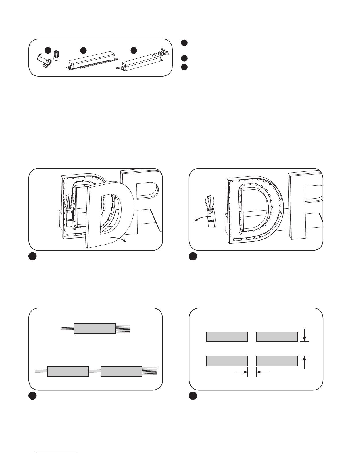
Prepare Electrical Wiring
Electrical Requirements
• Limited to use in dry and damp locations.
• The grounding and bonding of the LED Driver shall be done in
accordance with National Electric Code (NEC) Article 600.
• Follow all National Electric Codes (NEC) and local codes.
• These products are only suitable for connection to a circuit
from a Class 2 power source. These products have not been
evaluated for use when connected to a power source that does
not comply with Class 2 voltage and energy limited supplies.
BEFORE YOU BEGIN
Read these instructions completely and carefully.
This device complies with part 15 of the FCC Rules. Operation
is subject to the following two conditions: (1) This device may
not cause harmful interference, and (2) this device must
accept any interference received, including interference that
may cause undesired operation.
Note: This equipment has been tested and found to comply
with the limits for a Class A digital device, pursuant to part
15 of the FCC Rules. These limits are designed to provide
reasonable protection against harmful interference when the
equipment is operated in a commercial environment. This
equipment generates, uses, and can radiate radio frequency
energy and, if not installed and used in accordance with the
instruction manual, may cause harmful interference to radio
communications. Operation of this equipment in a residential
area is likely to cause harmful interference in which case the
user will be required to correct the interference at his own
expense.
This Class [A] RFLD complies with the Canadian standard
ICES-003. Ce DEFR de la classe [A] est conforme à la NMB-003
du Canada.
LED Control Module Features
• LED Control Module for GECLPS3 and GECLPS4 retrot.
• UL: Class 2 input.

Remove Existing Lighting Equipment
Electrical Connections
Turn off power and remove panel from the channel
letter.
1Remove the existing GECLPS3. Do not remove existing
channel letters and wiring.
NOTE: Follow all federal and local regulations when
disposing of existing LED drivers.
2
Prior to installation, survey the site for information regarding power and accessibility inside and outside the building. Ensure that the
branch circuit supplying the existing LED power supply will be within the voltage ratings of the new LED power supply, and have a
current rating not exceeding 20A, or that permitted by applicable local, state, or country electrical codes (whichever is less).
If removal of the existing lighting equipment (see Step 2 in this section) eliminates the disconnect switch, as required by applicable local,
state, or country electrical codes; a new disconnect switch must be installed. If required, the disconnect switch shall be installed by
qualied personnel, in accordance with applicable local, state, and country electrical codes.
Make sure the removal of lighting equipment does not compromise the integrity of the sign body (i.e. water intrusion). Fill in all holes
0.5 in. (13 mm) or smaller with the appropriate amount of rated caulk or sealant. For holes greater than 0.5 in. (13 mm), use an
aluminum or zinc coated steel patch with rivets and sealant.
=
GECLPS3
GECLPS3-2GEPS24-100-XX
One GECLPS3-2 and one 24VDC, 100W, Class 2 Tetra
LED Driver will be required to replace each GECLPS3 or
up to four GECLPS4 LED drivers.
NOTE: Mount the LED driver and LED control module
within the sign or other enclosure.
If installing multiple LED control modules or LED drivers in
the same compartment, keep them at least 2” (50.8mm)
apart end to end and 4” (101.6mm) apart along the sides.
NOTE: All drivers except GEPS24-180U must be installed
in a enclosure or be provided with a GEPSJB60 LED driver
extended enclosure.
3 4
4”
2”
LED driver LED driver
LED driver
LED driver
Components
1
2
3
UL certied 22-14 AWG (0.33-2.08 mm2) wire connectors or
22-18 AWG (0.33-0.82 mm2) .
Tetra®24 Volt Power Supply.
Tetra® LED Control Module.
1 2 3

123456
123456
8
9
1234 5 6
123456
123456
Dip Switch Setting Chart
Chart Assumes
LED Code of
“XX5”
Dip
Switch
Setting
GECLPS4 GECLPS3
Notes
6 LEDs/Ft.
(20/m) 5 LEDs/Ft.
(16/m) 6 LEDs/Ft.
(20/m) 5 LEDs/Ft.
(16/m)
Matches
Bin Code
16 ft.
(4.8m)
20 ft.
(6.1m)
64 ft.
(19.5m)
80 ft.
(24.4m)
Recommended
for Optimal
Performance
-1 20 ft.
(6.1m)
24 ft.
(7.3m)
80 ft.
(24.4m)
96 ft.
(29.3m)
Intensity of the
Tetra Strip will
be reduced by
approximately
10% to 20%
+1 12 ft.
(3.7m)
16 ft.
(4.8m)
48 ft.
(14.6m)
64 ft.
(19.5m)
Intensity of the
Tetra Strip will
be increased by
approximately
10% to 20%
With power off, set the correct dip switch according to the Dip Switch Setting Chart (see below for detailed explanation).
NOTE: For proper operation, verify that only one switch is set to the “ON” position.
Replace the dip switch cover and perform a quick test by turning the system on to ensure the channel letter LEDs are lit.
Dip Switch Settings
The following chart indicates the Tetra Strip load that can be placed on the Power Supply based on the character code on the LED and
the dip switch setting chosen. For example, when the Tetra Strip is marked with the character code HN3, the “3” on the dip switch can
be set to the ON position to achieve
neon-equivalent performance. At this
setting, the GECLPS3 power supply can
support up to 64 ft. (19.5m) of the 6 LED
per foot Tetra Strip. If you change the
dipswitch setting and ip #2 switch to
the ON position, the power supply can
support up to 80 ft. (24.4m) of Tetra
Strip. The footage guidelines vary based
on the type of Tetra Strip being used.
The charts below provide the footage
requirements for each Tetra Strip type.
CAUTION: Avoid setting the dip switch
to the ON position with any setting
not listed in the chart unless stated
otherwise. Exceeding maximum load of
any 4 load banks will cause the power
supply shut down Once the exceeded
load is removed, cycle the input power
will restart the power supply.
Wire AC line to LED driver(s) in
accordance with the applicable
local, state, and country electrical
codes. Connect black to black
or brown, white to white or blue,
and green to green using 18 AWG
(0.82mm2) wire connectors.
5Connect the red stripe wire (+)
of the LED control module to the
red wire (+) of the power supply.
Connect the white wire (-) of the
LED control module to the black or
blue wire (-) of the power supply.
Connect each LED control module
output lead pair to each Tetra LED
module supply lead pair using
UL certied wire connectors. Cap
each unused output lead with a UL
certied wire connector.
6 7
AC line
Black to black
or brown (-)
LED driver LED control module
Green to
green
White to white
or blue (+)
Red (+) Red stripe (+)
To LED modules
Cap unused leads
Inline connector
White (-)
Black or blue (-)
Character Code
of Tetra® Strip Dip Switch
Setting
XX1 1
XX2 2
XX3 3
XX4 4
XX5 5
XX6 6
WARNING: Do not connect outputs
in series or parallel.

Specications
Performance Data Min Typical Max
Input Voltage (VDC) 23 24 25
Input Current (A) - - 4
Output Voltage (VDC) 2.1 - 2.8
Output Current (ADC) - - 5.0
Output Power (W) - - 56
Environmental Operating Temperature Range -40°C +25°C +55°C*
Environmental Humidity (non-condensing) 0% - 95%
Environmental Storage Temperature Range -40°C - +85°C
Dimensions 9.5 in. x 1.7 in. x 1.2 in. (241 mm x 43.2 mm x 30.5 mm)
* Maximum case temperature is 85°C
NOTE: Power off the power supply when setting the dip switches.
NOTE: Do not connect outputs in series or parallel.
NOTE: When installing power supply, connect to the appropriate sized building breaker or disconnect device for line and neutral
connections, in accordance with local, state or country regulations.
NOTE: The grounding and bonding of the power supply and overall sign shall be done in accordance with National Electric Code
(NEC) Article 600.
SIGNXXX-R071514
GE Lighting Solutions • 1-888-MY-GE-LED • www.gelighting.com
1-888-69-43-533
GE Lighting Solutions, LLC is a subsidiary of the General Electric Company. Tetra is a trademark of GE Lighting Solutions, LLC. The GE brand and logo are trademarks of the General Electric Company.
© 2014 GE Lighting Solutions, LLC. Information provided is subject to change without notice. All values are design or typical values when measured under laboratory conditions.
This product is intended to be used as a lamp control gear that is installed after the mains control switch.
Conforms to the following standards:
GE Lighting 1975 Noble Rd, Cleveland, OH 44112
Table of contents
Other GE Home Lighting manuals
Popular Home Lighting manuals by other brands

Ingo Maurer
Ingo Maurer The MaMo Nouchies Yoruba Rose Floor instructions

Inspire
Inspire Irvine instruction manual

Arturo Alvarez
Arturo Alvarez MU02 Assembly instructions

JONATHAN Y
JONATHAN Y JYL2055A quick start guide

Safavieh Lighting
Safavieh Lighting VIOLETTA FLL4041A manual

Tomons
Tomons LP01003 instruction manual