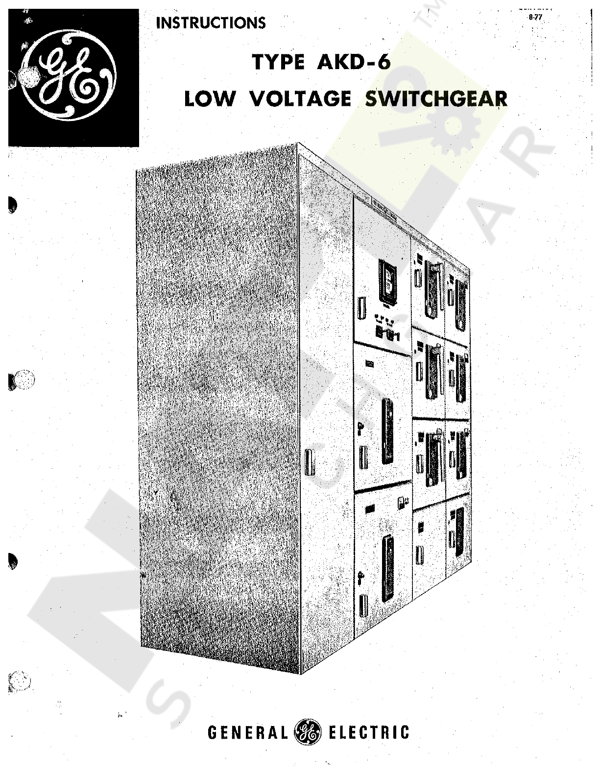
GE AKD-6 User manual
Other GE Industrial Electrical manuals

GE
GE QuiXtra 630 Quick start guide

GE
GE AKD-8 User manual

GE
GE AF-650 GP Series Operating instructions

GE
GE QuiXtra 4000 Quick start guide

GE
GE DS-19 User manual

GE
GE Entelliguard TU Conversion Kit User manual

GE
GE Spectra Series User manual

GE
GE Entellisys User manual

GE
GE GTP0060U0101 User manual

GE
GE Fuji Electric MICRO-SAVER AF-300 User guide

GE
GE RSTi-EP Instructions for use

GE
GE THQ Series User guide

GE
GE PHI 530.1425.2500 Manual

GE
GE AF-650 GP Series User manual

GE
GE ABB ReliaGear SB User manual

GE
GE PowerMark Plus DEH40228 User manual

GE
GE Spectra Series AMC6EB User manual

GE
GE Entellisys 4.0 User guide

GE
GE MicroVersaTrip Plus User manual

GE
GE A-Series II Panelboard User manual


Popular Industrial Electrical manuals by other brands

Rexroth Indramat
Rexroth Indramat DURADRIVE SYSTEM200 Project planning manual

Abtech
Abtech HVJB Series Installation, operation & maintenance instructions

Murata
Murata GRM0335C1H8R1DA01 Series Reference sheet

SAF-HOLLAND
SAF-HOLLAND CBX 5415.5 Installation and operation manual

Eaton
Eaton Ulusoy HMH24-04 user manual

Murata
Murata GJM0335C1E4R4BB01 Series Reference sheet

Newlong
Newlong NP-7H NSTRUCTION MANUAL/PARTS LIST

Stahl
Stahl 8575/12 operating instructions

SI
SI Pegasus installation instructions

Murata
Murata GRM1555C1H2R7CA01 Seies Reference sheet

Murata
Murata GRM0225C1E6R4BA03 Series Reference sheet

Cooper Power Systems
Cooper Power Systems VXE15 Installation and operation instructions

S&C
S&C Vista SD manual

Murata
Murata GRM0335C2A7R3CA01 Series Reference sheet

Siemens
Siemens 3VA9988-0BM10 operating instructions

Siemens
Siemens SITRANS LVS100 operating instructions

Murata
Murata GRM32ER60G227ME05 Series Reference sheet

Rockwell Automation
Rockwell Automation Allen-Bradley MP-Series installation instructions