6
BREAKER
4 Installation v4 Installation v
4 Installation v4 Installation v
4 Installation von M-Pon M-P
on M-Pon M-P
on M-PAA
AA
ACT PLCT PL
CT PLCT PL
CT PLUS LeistungsschalternUS Leistungsschaltern
US LeistungsschalternUS Leistungsschaltern
US Leistungsschaltern
BaugrBaugr
BaugrBaugr
Baugrößöß
ößöß
öße 1 und 2e 1 und 2
e 1 und 2e 1 und 2
e 1 und 2
4.1 Einbauor4.1 Einbauor
4.1 Einbauor4.1 Einbauor
4.1 Einbauortt
tt
t
Der Leistungsschalter soll in eine trockene, staubfreie, nicht korrosive
Atmosphäre eingebaut werden die des weiteren bezüglich Temperatur, Höhe
und Luftfeuchtigkeit den Richtlinien des IEC Standards IEC 947-1 entspricht.
Für spezielle Anwendungen die außerhalb der Standarddefinitionen liegen bitte
mit uns Rücksprache halten.
4.2 Festeinbau Schalter4.2 Festeinbau Schalter
4.2 Festeinbau Schalter4.2 Festeinbau Schalter
4.2 Festeinbau Schalter
Vor dem Anschluss des Schalters unbedingt Spannungsfreiheit sicherstellen.
Auch für Hilfspannungskreise.
4.3 Ausfahr4.3 Ausfahr
4.3 Ausfahr4.3 Ausfahr
4.3 Ausfahrtechniktechnik
techniktechnik
technik
Normaler Weise werden die Schalter für die Ausfahrtechnik zusammen mit der
Ausfahrtechnik geliefert .Zum Einbau des Einschubträgers muß zunächst der
Schalter entfernt werden (Siehe hierzu Abschnitt: “Ausfahren des
Leistungsschalters”).
Jetzt werden zunächst die Anschlüsse an die Sammelschienen oder Kabel
vorgenommen, dabei ist darauf zu achten das keine dauerhaften Zug-, Druck-
und Seiten- Kräfte auf den Einschubträger wirken.
Nach dem Anschluss der Hauptstrombahnen wird der Einschubträger mit M8
Schrauben an den hinter en und vorderen Befestigungslöchern befestigt. Diese
werden dann mit 25Nm angezogen. Es ist darauf zu achten das der
Einschubträgen nach der Montage keine Verformungen aufweißt und die
rechteckige Form weiter gegeben ist.
Wenn die Montage abgeschlossen ist muss die freie Bewegung der
Berührungsschutzabdeck ungen überprüft werden.
Zur Erdung ist der Einschubträger auf der rechten Seite (von Vorne gesehen) mit
einem Er dungspunkt versehen.
5 Betrieb Leistungsschalter5 Betrieb Leistungsschalter
5 Betrieb Leistungsschalter5 Betrieb Leistungsschalter
5 Betrieb Leistungsschalter
5.1 Einschaltv5.1 Einschaltv
5.1 Einschaltv5.1 Einschaltv
5.1 Einschaltvoror
oror
organg:gang:
gang:gang:
gang:
Federkraftspeicher mit dem Handspannhebel spannen (Ca 7-8 Hübe erforderlich
zum vollständigen Spannen).
Ist der Leistungsschalter mit einem Motorantrieb ausgestattet beginnt der
Spannvorgang sobald dieser angesteuert wird.Drücken des Ein-Knopfes oder
Erregen der Einschaltspule (wennv orhanden) bewirkt die sofortige Einschaltung
des Schalter.
Der Schalter kann nicht eingeschaltet werden wenn:
• Wenn der AUS-Knopf gedrückt ist
• Wenn der Schalter in Ausfahrtechinik sich zwischen den positionen Trenn-,
Test- and Betriebsstellung befindet.
• Wenn am Mpro der Rückstellknopf hervorragt (Knopf drücken um wieder
Einschaltbereit zu sein)
• Ein Unter spannungsauslöser installiert und spannungslos ist
• Der Schalter sich in der Test- oder Betriebsstellung befindet und die Handkurbel
in der Öffnung steckt.
• Eine Zylinderschlossverriegelung aktiviert ist oder eine andere Verriegelung
(Kabelverriegelung) am Schalter angebaut und aktivier tist .
5.2 Ausschaltv5.2 Ausschaltv
5.2 Ausschaltv5.2 Ausschaltv
5.2 Ausschaltvoror
oror
organg:gang:
gang:gang:
gang:
Die Betätigung des Aus-Knopfes oder das Ansprechen des Arbeitsstromauslösers
(Falls vorhanden) bewirkt das Ausschalten.
Die Auslösung unter Fehlerbedingungen geschieht automatisch in Abhängigkeit
der gewählten Parameter für die Auslöseeinheit.
4 Installing M-P4 Installing M-P
4 Installing M-P4 Installing M-P
4 Installing M-PAA
AA
ACT PLCT PL
CT PLCT PL
CT PLUS Frame 1 & 2US Frame 1 & 2
US Frame 1 & 2US Frame 1 & 2
US Frame 1 & 2
CirCir
CirCir
Circuit Brcuit Br
cuit Brcuit Br
cuit Breakeak
eakeak
eakerer
erer
erss
ss
s
4.1 Fitting4.1 Fitting
4.1 Fitting4.1 Fitting
4.1 Fitting
Install the switch in a dry, dust-free, non-corrosive, room, with temperature,
height and humidity in compliance with standard IEC 947-1.
For installations in special rooms or rooms which exceed the limits laid down by
the standard contact GE Consumer & Industrial.
4.24.2
4.24.2
4.2 Fixed typeFixed type
Fixed typeFixed type
Fixed type
Before connecting the main and auxiliary conductors of the circuit breaker and
its accessories, as auxiliary switches and releases, care is to be taken that all
conductors, connectors and terminals are not ener gized.
4.3 Draw4.3 Draw
4.3 Draw4.3 Draw
4.3 Drawout typeout type
out typeout type
out type
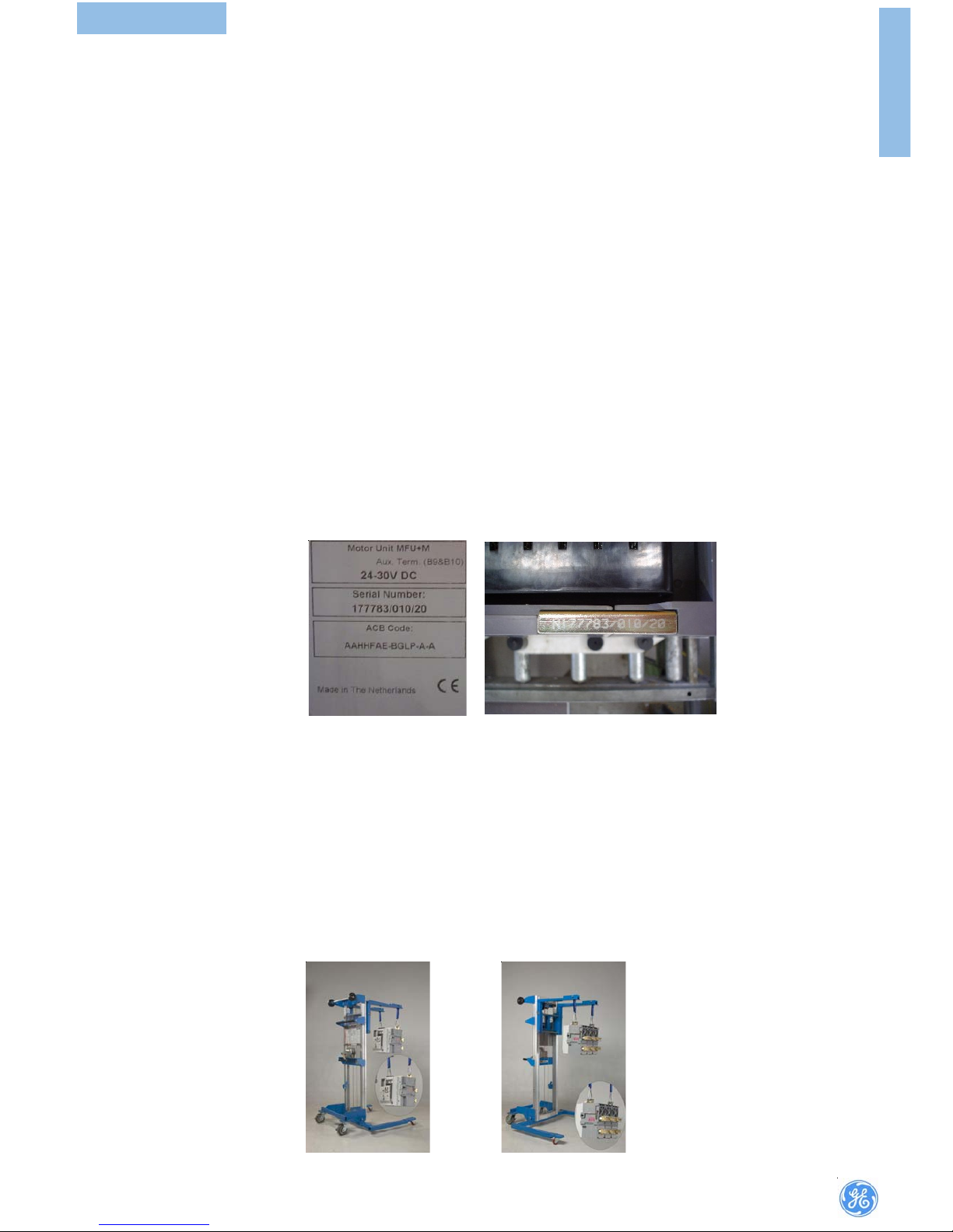
Normally, drawout type circuit breakers will be delivered already mounted in
cassettes.Remove the breaker from its cassette using procedures described in
the section ‘Withdrawal of M-PACT Plus Circuit Breaker’.Position the cassette
as required in the switchboard.
Note: The cassette may be lifted by hand but, if a handling truck or other lifting
gear is employed, all four of the lifting holes provided at front and rear of the
cassette should be used.
Position cassette in place and connect incomming and outgoing cables/busbars.
When connecting busbars ensure there is minimal deflection/stress to the back
of the cassette. Fix the cassette using 4 off M8 bolts to 25Nm at front and rear
fixing points. Note, the cassette base before and after fixing must be flat and
the frame square.
Check that the safety shutters move freely after the fixing bolts have been fully
tightened.
An earthing point is provided on the right hand side of each cassette (viewed
from front).
5 Operation5 Operation
5 Operation5 Operation
5 Operation
5.1 Closing pr5.1 Closing pr
5.1 Closing pr5.1 Closing pr
5.1 Closing procedurocedur
ocedurocedur
oceduree
ee
e
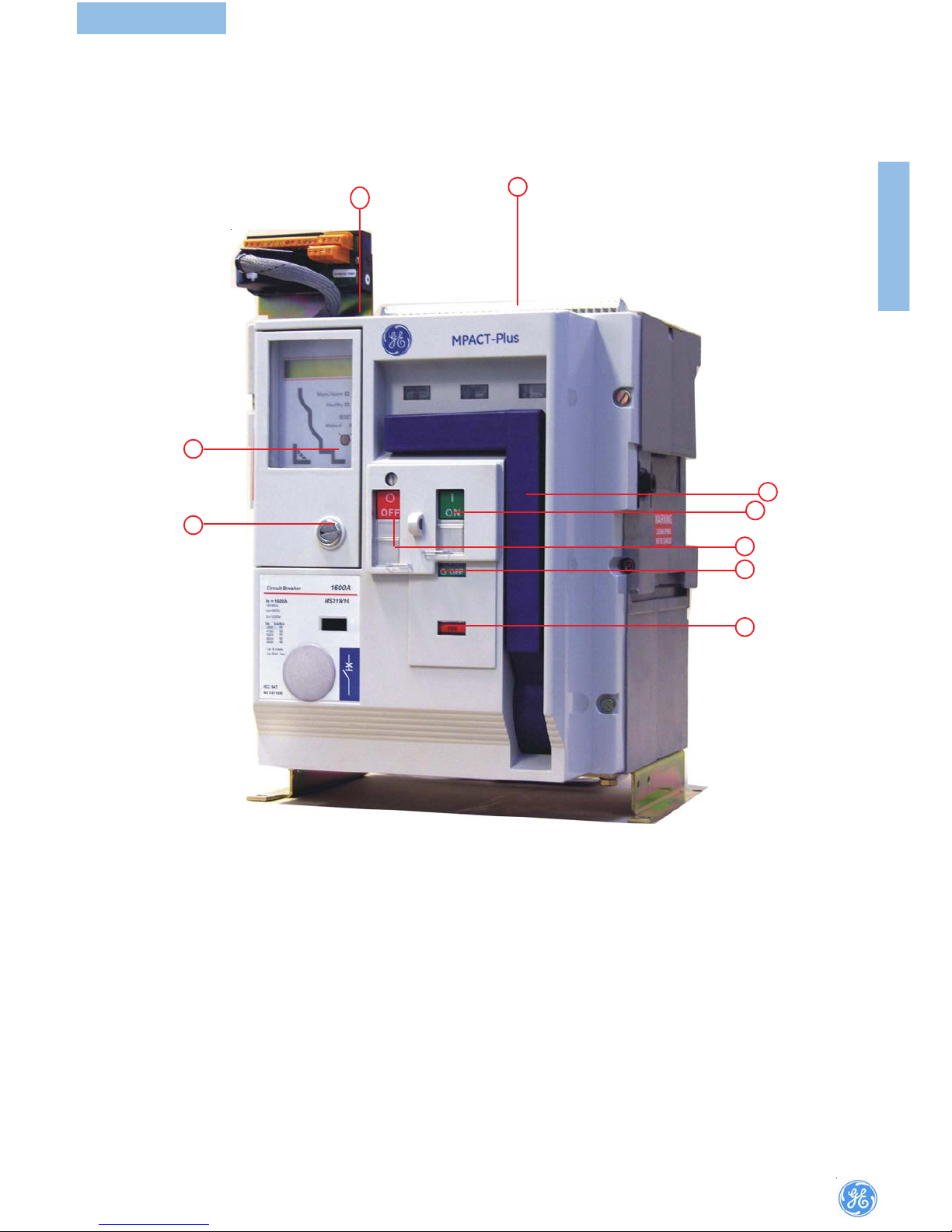
Pull the charging handle out and down to charge the closing springs (requires
approximately 7-8 movements of the handle to fully charge).
If a motorised spring charging unit is fitted, the springs will be automatically
charged as soon as the motor is energized. Pressing the ON pushbutton or
energising the closing coil (if fitted) will close the circuit breaker.
Closing cannot occur if:
• The OFF button is in a depressed position.
• The breaker is positioned anywhere between CONNECTED, TEST and
DISCONNECTED positions.
• The electronic pr otection unit is at ‘Manual Reset’ and the reset button is
protruding from the front fascia. (Press the reset button to clear the breaker
for closing).
• An undervoltage trip is fitted but not energized.
• The breaker is in the TEST or CONNECTED position with the racking handle
inserted.
• A key interlock(e.g. Castell etc.) or direct interbreak er mechanical interlock
is operating on the breaker.
5.2 Opening pr5.2 Opening pr
5.2 Opening pr5.2 Opening pr
5.2 Opening procedurocedur
ocedurocedur
oceduree
ee
e
Pressing the OFF pushbutton or energisation of the shunt trip coil (if fitted) will
open the breaker.
Tripping under fault conditions will be automatic depending in settings used for
the protective devices.
Normally, drawout type circuit breakers will be delivered already mounted in
cassettes.
INSTALLATIONOPERATION