Probotix COMET User manual

www.probotix.com
844-472-9262
GALAXY SERIES CNC ROUTERS
Quick Start Guide

http://www.probotix.com/forum/
http://www.probotix.com/wiki/
Online Support
844-472-9262
HOW TO GET HELP
Telephone Support

MACHINE FOOTPRINTS

BUILDING A TABLE - COMET
31.5”
34”
36”
3/4” MDF or Plywood, 34” x 36”
A
B
CD
E
F
G
H
A
3/4” MDF or Plywood, 24.5” x 34.5”
B
2pcs 1x4 Pine, 34” Long
C
2pcs 1x4 Pine, 34.5” Long
D
2pcs 1x4 Pine, 25.5” Long
E
2pcs 1x4 Pine, 33” Long
F
4pcs 4x4 Pine, 27.25” Long
G
4pcs 3.5” Tall Locking Castors
H

BUILDING A TABLE - ASTEROID
31.5”
46”
36”
3/4” MDF or Plywood, 46” x 36”
A
B
CD
EF
G
H
A
3/4” MDF or Plywood, 37.5” x 34.5”
B
2pcs 1x4 Pine, 46” Long
C
2pcs 1x4 Pine, 34.5” Long
D
2pcs 1x4 Pine, 37.5” Long
E
2pcs 1x4 Pine, 33” Long
F
4pcs 4x4 Pine, 27.25” Long
G
4pcs 3.5” Tall Locking Castors
H

BUILDING A TABLE - METEOR
31.5”
34”
64.5”
3/4” MDF or Plywood, 34” x 64.5”
A
B
C
D
E
F
G
H
A
3/4” MDF or Plywood, 25.5” x 63”
B
2pcs 1x4 Pine, 34” Long
C
2pcs 1x4 Pine, 63” Long
D
2pcs 1x4 Pine, 25.5” Long
E
2pcs 1x4 Pine, 61.5” Long
F
4pcs 4x4 Pine, 27.25” Long
G
4pcs 3.5” Tall Locking Castors
H

BUILDING A TABLE - NEBULA
31.5”
46”
64.5”
3/4” MDF or Plywood, 46” x 64.5”
A
B
C
D
E
F
G
H
A
3/4” MDF or Plywood, 37.5” x 63”
B
2pcs 1x4 Pine, 46” Long
C
2pcs 1x4 Pine, 63” Long
D
2pcs 1x4 Pine, 37.5” Long
E
2pcs 1x4 Pine, 61.5” Long
F
4pcs 4x4 Pine, 27.25” Long
G
4pcs 3.5” Tall Locking Castors
H

A
D
E
F
G
C
C
B
A
D
E
F
G
C
B
UNITY CONTROLLER
COMPUTER
110VAC POWER
MACHINE HARNESS
PARALLEL CABLE
USB CABLE
KEYBOARD, MOUSE, MONITOR, JOG PENDANT
CONNECTION DIAGRAM (ROUTER)

A
D
E
F
G
C
HB
A
D
E
F
G
C
B
UNITY CONTROLLER
COMPUTER
110VAC POWER
MACHINE HARNESS
PARALLEL CABLE
USB CABLE
KEYBOARD, MOUSE, MONITOR, JOG PENDANT
CONNECTION DIAGRAM (VFD SPINDLE)
C
J
H
I
VFD
I
J220VAC
VFD CONTROL CABLE

A
B
C
MDE
L
J
FG H I
N
O
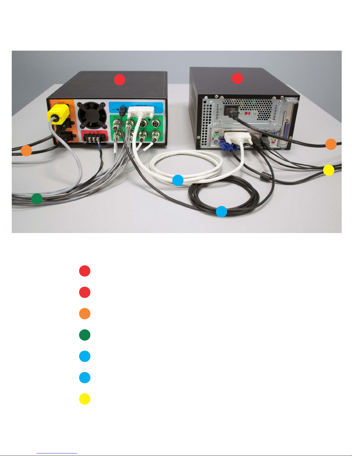
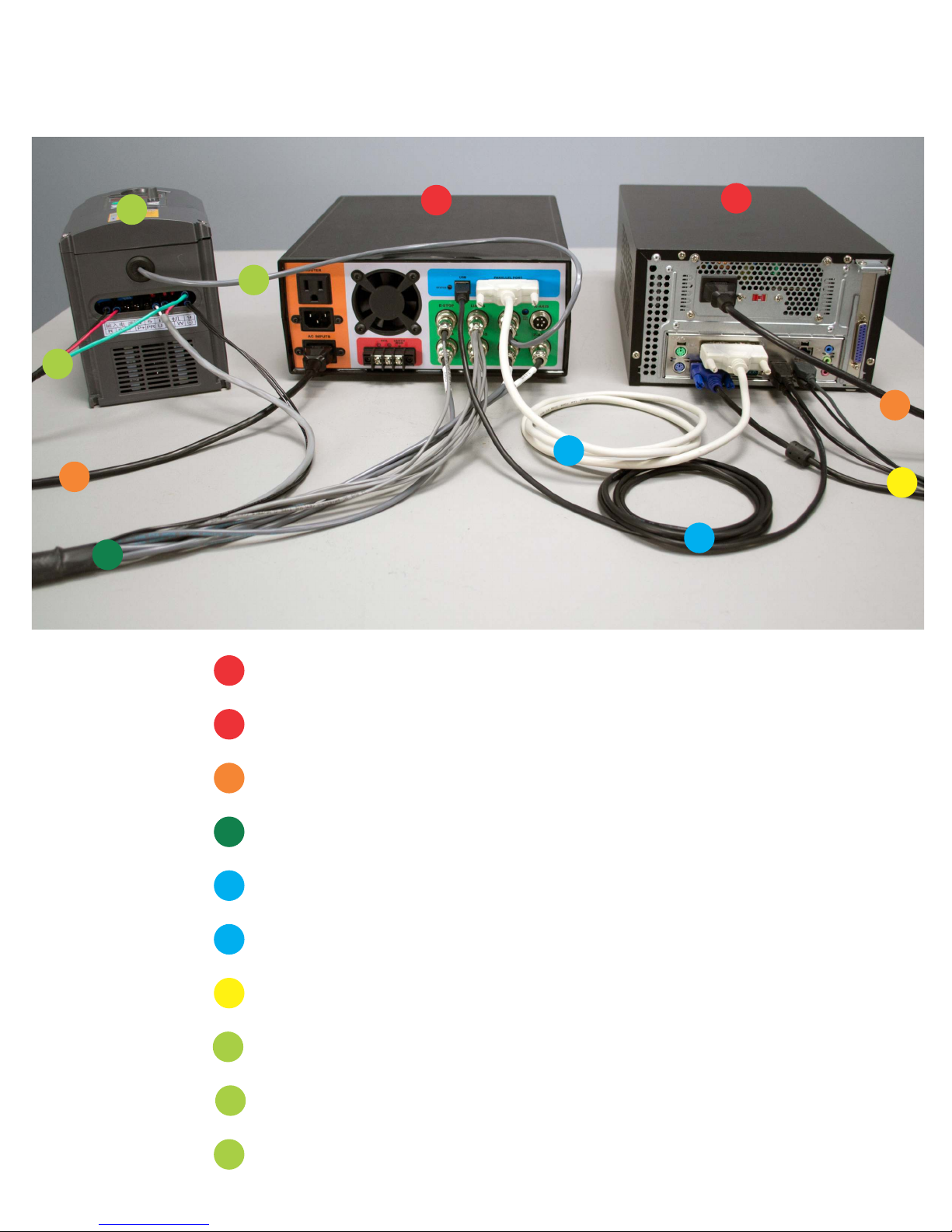
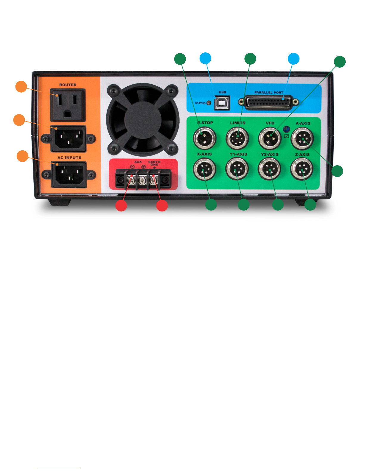
A: AC INPUT - Primary power input for power supply.
B: AC INPUT - Power input here is switched by relay to the (C) ROUTER output.
C: ROUTER - Connect to the green power cable from the machine harness. On-screen spindle controls, as well as
M3/M5 g-codes will control this output. When a VFD spindle is used instead of a router, this outlet
can be used with for a shop vac and is controlled by M8/M9.
D: USB - Connect to USB connector on PC.
E: PARALLEL PORT - Connect to the primary (built onto the motherboard) DB-25 connector on the PC.
F, G, H, I, J: MOTOR CONNECTIONS - Connect to each of the labeled motor connections from the machine harness.
J: A-AXIS - For optional rotary axis.
K: VFD - Connect to 3-pin VFD pigtail for speed control of a VFD spindle.
L: LIMITS - Connect to the 8-pin limit switch connector from the machine harness.
M: E-STOP - Connect to the 2-pin e-stop connector from the machine harness.
N: EARTH GND - It is recommended that the machine is grounded to earth. Connect the two black wires from the
machine harness to this connection. If using a VFD, ground the machine frame to the VFD earth ground
terminal instead. Additional earth grounding may be necessary when working with certain spindles or
certain types of materials that may cause excess EMI or static electricity.
O: AUX - This is a 5V logic level signal that can be connected to a PowerSwitch Tail or other 5V@20mA relay circuit.
This signal is controlled by the flood coolant controls in the software (M8/M9). Do not use if running a VFD
spindle.
UNITY CONTROLLER PORTS
K

VFD WIRING DETAIL
220VAC@20AMP
1
2
34
SPINDLE
U,V,W
TO SPEED
CONTROL BOARD
1) 24V PWR (RED)
2) GND (BLK)
3) 0-10V (WHT)
EARTH GND
JUMPER
SET TO “VI”
1
2
3
TO MACHINE FRAME
VI
24V
DCM/ASM
NOTICE: Internal wiring of Chinese spindles is not consistent. If spindle spins in reverse, swap U & V.
You MUST verify visually or physically the proper rotation of the spindle to ensure the machine cuts properly!

VFD WIRING DETAIL
(SUNFAR E300)
220VAC@20AMP
1
2
34
SPINDLE
U,V,W
TO SPEED
CONTROL BOARD
1) 24V PWR (RED)
2) GND (BLK)
3) 0-10V (WHT)
EARTH GND
1
2
3
TO MACHINE FRAME
VI
24V
CM
NOTICE: Internal wiring of Chinese spindles is not consistent. If spindle spins in reverse, swap U & V.
You MUST verify visually or physically the proper rotation of the spindle to ensure the machine cuts properly!

VFD WIRING DETAIL
(SUNFAR E500)
220VAC@20AMP
1
2
34
SPINDLE
U,V,W
TO SPEED
CONTROL BOARD
1) 24V PWR (RED)
2) GND (BLK)
3) 0-10V (WHT)
EARTH GND
1
2
3
TO MACHINE FRAME
AI
24V
GND
NOTICE: Internal wiring of Chinese spindles is not consistent. If spindle spins in reverse, swap U & V.
You MUST verify visually or physically the proper rotation of the spindle to ensure the machine cuts properly!

LIMIT SWITCHES
The Y1 and Y2 limit switches have been removed to protect them during
transport. Reinstall them as seen above before running the machine.

Simple Start Up Procedure:
ŸStart computer
ŸLaunch LinuxCNC from icon on desktop
ŸTurn power on Unity Controller
ŸVerify red E-Stop indicator follows physical e-stop
ŸClick orange Machine Power button
ŸClick the Home All button
ŸClick folder icon to open g-code file
ŸLoad tool into spindle or router
ŸMount stock on the table
ŸJog machine to place tool on origin of part
ŸPerform touch-off sequence (all 3 axis)
ŸVerify spindle power switch is on
ŸHit the Run button
ŸWatch in awe
*There are additional instruction in the wiki for using the Z
Touch-off puck and the ATLaS Automatic Tool Length
Sensor.
GETTING STARTED

You can use any CAM software to generate g-code for LinuxCNC. Most CAM software
programs will have appropriate post processors named either LinuxCNC or EMC2. You
can use generic g-code post processors as well. We also have post processors on our
wiki specifically for our machines. If using the ATLaS Automatic Tool Length Sensor, you
need to make sure the post processor you are using is inserting the proper tool change
routine.
CNC machines use a numbered coordinate system. G54 is the default coordinate
system. Some post processors carelessly do not insert a coordinate system. The
results of not specifying a coordinate system in the g-code is unpredictable and
dangerous. Be sure the coordinate system is being inserted into the g-code preamble.
After you mount your stock to the table and insert the tool you will be cutting with, use
the jog controls to move the tool to the origin of the part. This is the same location you
told the CAM software you wanted the origin to be. It could be on one of the corners of
the part, or top center of the part. Then choose each axis and click the
button.
CAM SOFTWARE
G54 COORDINATE SYSTEM
TOUCHING OFF
The current position of the
tool relative to the stock at
this moment. May be zero,
may be the thickness of the
piece of paper you are
sliding under the tool.
This needs to match the
coordinate system that the
CAM software is inserting
into the g-code.
The axis that we are setting the origin for.

Except for in the case of full 90 degree arcs, CAM software will break any curves in
your designs up into a bunch of tiny segments. This will create jittery motion, will create
tool marks in the part, shorten your tool life, and can extend the cut times significantly.
Fortunately, LinuxCNC has a mode called G64 path optimization.
When G64 is turned on, LinuxCNC will perform a look-ahead and calculates the angle
of the next segment(s), only slowing down as little as possible to round the corner(s). It
tries to maintain the programmed velocity as close as possible, while not violating the
velocity and acceleration capabilities of the machine. If G64 is programmed without a P
parameter, LinuxCNC will take its liberty and round over those corners as much as it
needs, the faster the feedrate, the greater the deviation from the programmed location.
While cutting a square at only 10IPM will be a near perfect square, cutting that same
square at 100IPM will result in 3 extremely rounded corners. In LinuxCNC, G64 is
turned on by default (look for it under active g-codes under the MDI tab), but it does not
have this P parameter (tolerance) by default.
The simple solution is to type G64 P0.010 into the MDI command box and hit go. This
will tell LinuxCNC to yes, turn on path optimization, but do not deviate more than 0.010"
from where I told you to go. The tolerance you use will depend upon the types of parts
you are making. You will want to set it to 0.010 or more for decorative type things,
especially while 3D carving. For more precise parts, You will use 0.001. G61 cancels
G64 and will cause the machine to come to a complete stop at the end of every
segment.
One more thing... You can put that G64 line in the preamble of your post processor so
that it inserts it into every g-code file. It is modal, so it stays the same unless explicitly
changed with another G64 Pxxx, or canceled with a G61. It also resets when the
software is restarted. The most efficient way to manage this is to create seperate post
processor for each tolerance level you want to use.
Do not confuse G64 Path Optimization with the G54 Coordinate System
G64 PATH OPTIMIZATION
More information about this and other
topics can be found on the wiki:
http://www.probotix.com/wiki/

Daily Use:
Put a couple of drops of 3-in-1 oil on each of the six linear rails before homing the
machine each day. This will allow a tiny amount of oil to be sucked up into the
bearing housings before cutting any parts.
Use the included linear motion grease on the leadscrews. A light coating is enough,
as Delrin is self-lubricating. You can use WD-40 and an air nozzle to remove debris
from the screw. Be sure to dry the screw of the WD-40 before re-applying grease
as WD-40 is a solvent and will dissolve the grease.
The Grease Zerks on the z-axis bearings are not used.
All of the other bearings are sealed. The most important thing is to keep any dust
cleaned off of the machine, especially if you are cutting abrasive materials such as
MDF, fiberglass, or carbon fiber.
High Humidity Environments & Storage:
If you use your machine in a high humidity environment, ie in a shed or other non-
airconditioned environment, or if you plan to store it without use, rust can form on
the linear rails, leadscrews, and the black-oxide machine fasteners. Coat these
surfaces with grease or WD-40 often. Again, be sure to dry the screws and rails of
the WD-40 before re-applying grease and oil before use. The black-oxide machine
fasteners will not need to wiped dry.
Bearing Replacements:
Depending on the amount of use and the loads on the machine for your application,
the linear bearings and leadscrew ball bearings will need to be replaced eventually.
You will notice excess slop, marks on the rails, or jerky motion on the affected axis.
Replace them annually for worry free operation.
Anti-backlash Nuts:
The Delrin anti-backlash nuts are designed to wear and may need to be replaced
periodically, depending upon the amount of use and abuse your machine receives.
When they fail, you will notice backlash on the affected axis. You can check them
by pulling and pushing on each axis and observing slop between the leadscrew
and the drive nuts. The replace them, you will need to remove the leadscrews.
Replace them annually for worry free operation.
MAINTENANCE

ESCAPE
E-STOP
F1
TOGGLE E-STOP
F2
TOGGLE MACHINE POWER
F3
MANUAL MODE
F4
AUTO MODE
F5
MDI MODE
F6
RESET INTERPRETER
F7
TOGGLE MIST
F8
TOGGLE FLOOD
F9
TOGGLE SPINDLE FORWARD
F10
TOGGLE SPINDLE REVERSE
F11
DECREASE SPINDLE SPEED
F12
INCREASE SPINDLE SPEED
X
SELECT X-AXIS
Y
SELECT Y-AXIS
Z
SELECT Z-AXIS
LEFT/RIGHT ARROW
JOG X-AXIS
UP/DOWN ARROW
JOG Y-AXIS
PAGE UP/DOWN
JOG Z-AXIS
HOME
HOME SELECTED AXIS
END
TOUCH-OFF SELECTED AXIS
</>
DECREASE/INCREASE JOG SPEED
C
SELECT CONTINUOUS JOGGING
I
SELECT INCREMENTAL JOGGING AND TOGGLE BETWEEN INCREMENTS
1-9,0
FEED OVERRIDE 10%-90%, 0 IS 100%
@
TOGGLE COMMANDED/ACTUAL POSITION DISPLAY
#
TOGGLE ABSOLUTE/RELATIVE POSITION DISPLAY
O
OPEAN A PROGRAM
R
RUN THE OPENED PROGRAM
P
PAUSE PROGRAM
S
RESUME PAUSED PROGRAM
A
STEP ONE LINE IN PAUSED PROGRAM
B
TAKE SPINDLE BREAK OFF
ALT-B
PUT SPINDLE BRAKE ON
ALT-S
START LOGGING
ALT-P
PAUSE LOGGING
ALT-F
SAVE LOG FILE
CTRL-P
PRINT LOG FILE (ONLY WITH XGRAPH)
LINUXCNC KEYBOARD SHORTCUTS

G0
G1
G2, G3
G38.2
G80
G81
G82…G89
G33
G33.1
G76
G17
G18
G19
G90
G91
G93
G94
G95
G20
G21
G41, G42
G41.1, G42.1
G40
G43
G43.1
G49
G98
G99
G61
G61.1
G64
M0
M2
M1, M30, M60
M3, M4
M5
G96
G97
M7
M8
M9
F
S
T
M50…M53
G54…G59, G59.1…G59.3
O …
M6
G4
G10 L2
G28
G30
G53
G92
G92.1
G92.2
G92.3
M101…M199
(…)
(MSG,…)
(DEBUG,…#123…#<foo>)
(PRINT,…#123…#<foo>)
I J K or R
R L P
R L P Q
K
K
P Z I J R K Q H L E
D
D L
H
I K
P
S
D S
P0 (off) or P1 (on)
sub/endsub, while/endwhile,
if/else/endif, do/while, call,
break/continue/return
T
P
P X Y Z A B C
X Y Z A B C
P Q
Rapid motion
Coordinated motion ("Straight feed")
Coordinated helical motion ("Arc feed") CW or CCW
Straight Probe
Cancel motion mode
Drilling Cycle
Other canned cycles
Spindle-synchronized motion
Rigid Tapping
Multipass lathe threading cycle
Select XY plane
Select XZ plane
Select YZ plane
Absolute distance mode
Incremental distance mode
Inverse time feed rate
Units per minute feed rate
Units per revolution
Inches
Millimeters
Start cutter radius compensation left or right
Start cutter radius compensation left or right, transient tool
Cancel cutter radius compensation
Use tool length offset from tool table
Use specified tool length offset for transient tool
Cancel tool length offset
Retract to R position
Retract to prior position
Exact Path mode
Exact Stop mode
Continuous mode with optional path tolerance
Pause Program
End Program
Other stop codes
Turn spindle clockwise or counterclockwise
Stop spindle
Constant surface speed mode (foot/minute or meter/minute) with top speed
RPM mode
Turn mist on
Turn flood on
Turn all coolant off
Set Feed Rate
Set Spindle Speed
Select Tool
Feed Override, Spindle Override, Adaptive Feed, Feed Hold
Select coordinate system
Change tool
Dwell (seconds)
Coordinate system origin setting
Return to home
Return to secondary home
Motion in machine coordinate system
Offset coordinate systems and set parameters
Cancel offset coordinate systems and set parameters to zero
Cancel offset coordinate systems but do not reset parameters
Apply parameters to offset coordinate systems
User-defined M-codes
A comment "…" to the user
Display the message "…" to the user (e.g., in a popup)
Display the message (with variables substituted) like MSG
Display the message (with variables substituted) to stderr
Motion
Plane Selection (affects G2, G3, G81…G89, G40…G42)
Distance Mode
Feed Rate Mode
Units
Cutter Radius Compensation
Tool Length Offset
Return Mode in Canned Cycles
Path Control Mode
Stopping
Spindle Control
Coolant
Other Modal Codes
Flow-control Codes
Non-modal Codes
G-CODE QUICK REFERENCE
Other manuals for COMET
2
This manual suits for next models
3
Table of contents