MOKENEYE OM01Z User manual

20V CORDLESS OSCILLATING MULTI TOOL
Model OM01Z
WARNING:Toreducetheriskofinjury,theusermustreadandunderstandthe
Owner'sManualbeforeusingthisproduct.Savetheseinstructionsforfuturereference.
Owner’s Manual
VERSION: OM01Z-EN-03
20V
MAX
BATTERY
2.0Ah

2
TABLE OF CONTENTS
GENERAL SAFETY WARNINGS .................2
SAFETY WARNINGS FOR OSCILLATING
MULTI TOOL..............................................3
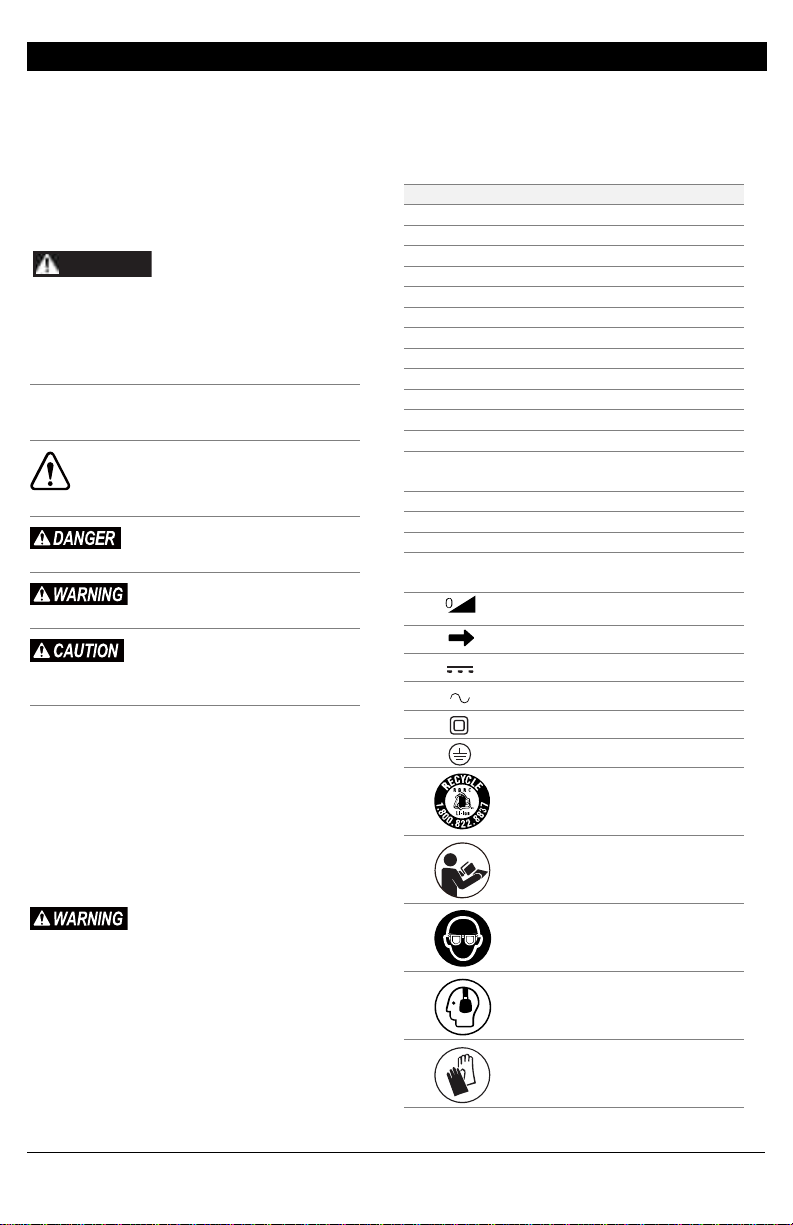
SYMBOLS...................................................4
SPECIFICATIONS .......................................5
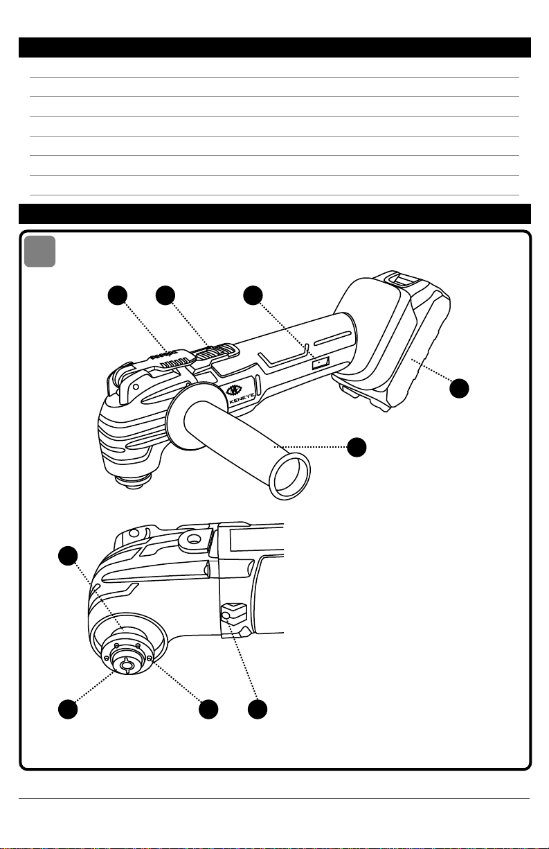
GET TO KNOW THE TOOL.........................5
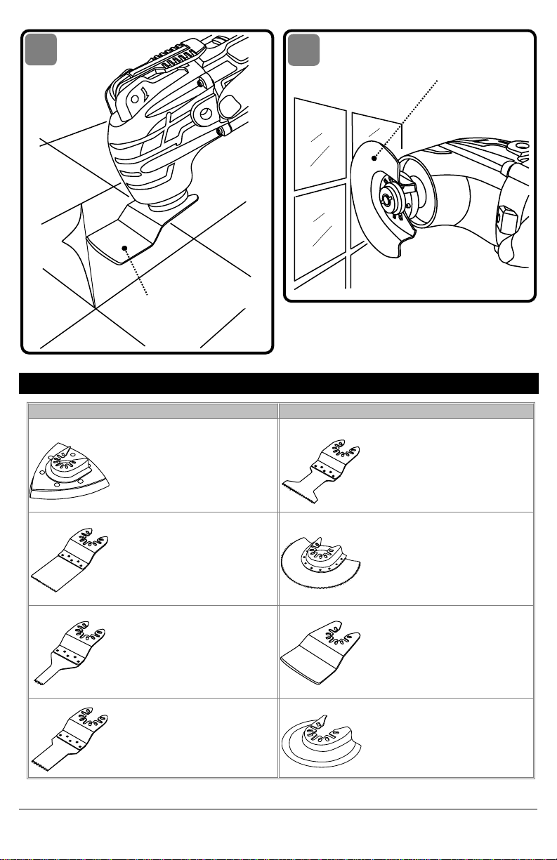
SELECTING THE ACCESSORY ....................8
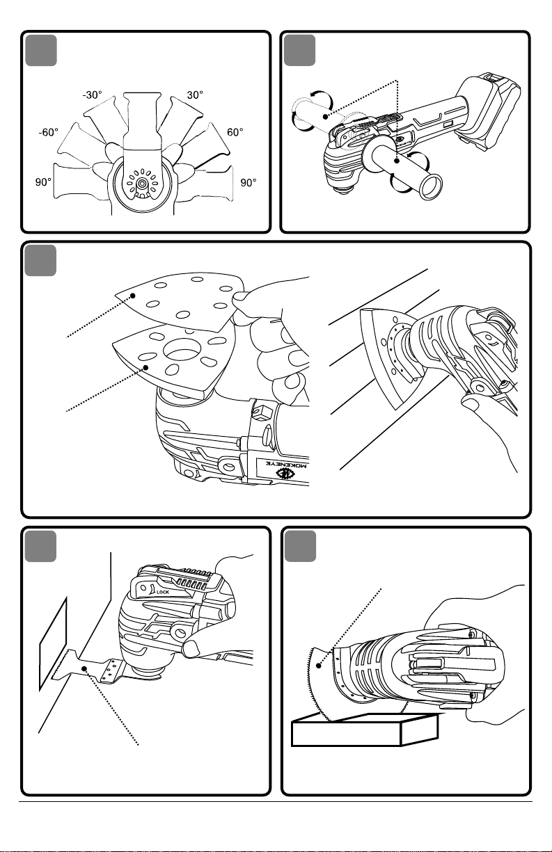
OPERATING INSTRUCTIONS.....................9
MAINTENANCE.......................................12
TROUBLE SHOOTING..............................13
LIMITED WARRANTY..............................13
•
Some dust created by power sanding, sawing, grinding,
drilling and other construction activities contains
chemicals known to the State of California to cause
cancer, birth defects or other reproductive harm. Some
examples of these chemicalsare:
–
Lead from lead-based paints.
–
Crystalline silica from bricks, cement, and other
masonryproducts.
–
Arsenic and chromium from chemically-treated
lumber.
•
Your risk from these exposures varies, depending upon
how often you do this type of work. To reduce your
exposure to these chemicals:
–
Work in a well-ventilated area.
–
Work with approved safety equipment, such as dust
masks that are specially designed to filter out
microscopic particles.
–
Avoid prolonged contact with dust from power
sanding, sawing, grinding, drilling, and other
construction activities. Wear protective clothing and
wash exposed areas with soap and water. Allowing
dust to get into your mouth or eyes or to lie on the
skin may promote absorption of harmful chemicals.
GENERAL SAFETY WARNINGS
Read all safety warnings,
instructions, illustrations and
specifications provided with this power tool. Failure
to follow all instructions listed below may result in
electric shock, fire and/or serious injury.
SAVEALLWARNINGSAND
INSTRUCTIONSFORFUTUREREFERENCE.
The term"power tool" inthe warningsrefers toyour
mains-operated (corded) power tool or battery-
operated (cordless) power tool.
WORK AREA SAFETY
• Keep work area clean and well lit. Cluttered or
dark areas invite accidents.
• Do not operate power tools in explosive
atmospheres, such as in the presence of
flammable liquids, gases or dust. Power tools
create sparkswhich may ignitethe dustor fumes.
• Keep children and bystanders away while
operating a power tool. Distractions can cause
you to lose control.
ELECTRICAL SAFETY
• Power tool plugs must match the outlet. Never
modify the plug in any way. Do not use any
adapter plugs with earthed (grounded) power
tools. Unmodified plugs and matching outlets will
reduce risk of electric shock.
• Avoid body contact with earthed or grounded
surfaces, such as pipes, radiators, ranges and
refrigerators. There is an increased risk of electric
shock if your body is earthed or grounded.
• Do not expose power tools to rain or wet
conditions. Water entering a power tool will
increase the risk of electric shock.
• Do not abuse the cord. Never use the cord for
carrying, pulling or unplugging the power tool.
Keep cord away from heat, oil, sharp edges or
moving parts. Damaged or entangled cords
increase the risk of electric shock.
• When operating a power tool outdoors, use an
extension cord suitable for outdoor use. Use of a
cord suitable for outdoor use reduces the risk of
electric shock.
• If operating a power tool in a damp location is
unavoidable,use aground faultcircuit interrupter
(GFCI)protectedsupply.Useofa GFCIreduces the
risk of electric shock.
PERSONAL SAFETY
• Stay alert, watch what you are doing and use
common sense when operating a power tool. Do
not use a power tool while you are tired or under
the influence of drugs, alcohol or medication. A
momentofinattentionwhileoperatingpowertools
may result in serious personal injury.
• Use personal protective equipment. Always wear
eye protection. Protective equipment such as a
dust mask, non-skid safety shoes, hard hat or
hearing protection used for appropriate conditions
will reduce personal injuries.
• Prevent unintentional starting. Ensure the switch is
in the off-position before connecting to power
source and/or battery pack, picking up or carrying
the tool. Carrying power tools with your finger on
the switch or energizing power tools that have the
switch on invites accidents.
•Remove any adjusting key or wrench before
turning the power tool on. A wrench or a key left
attached to a rotating part of the power tool may
result in personal injury.
• Donot overreach.Keepproperfooting andbalance
at all times. This enables better control of the
power tool in unexpected situations.
• Dress properly. Do not wear loose clothing or
jewellery.Keep your hair,clothing andglovesaway
from moving parts. Loose clothes,jewellery orlong
hair can be caught in moving parts.
• If devices are provided for the connection of dust
extractionandcollectionfacilities,ensuretheseare

3
connected and properly used. Use of dust
collection can reduce dust- related hazards.
• Do not let familiarity gained from frequent use of
tools allow you to become complacent and ignore
tool safety principles. A careless action can cause
severe injury within a fraction of a second.
POWER TOOL USE AND CARE
• Donotforce thepower tool.Use thecorrect power
tool for your application. The correct power tool
will do the job better and safer at the rate for
which it was designed.
• Do not use the power tool if the switch does not
turn it on and off. Any power tool that cannot be
controlledwith theswitch isdangerous andmust
be repaired.
• Disconnect the plug from the power source
and/or remove the battery pack, if detachable,
from the power tool before making any
adjustments, changing accessories, or storing
power tools. Such preventive safety measures
reduce the risk of starting the power tool
accidentally.
• Storeidlepowertoolsoutof thereach ofchildren
and do not allow persons unfamiliar with the
power tool or these instructions to operate the
power tool. Power tools are dangerous in the
hands of untrained users.
• Maintain power tools and accessories. Check for
misalignment or binding of moving parts,
breakage of parts and any other condition that
may affect the power tool's operation. If
damaged, have the power tool repaired before
use. Many accidents are caused by poorly
maintained power tools.
• Keep cutting tools sharp and clean. Properly
maintained cutting tools with sharp cutting
edges are less likely to bind and are easier to
control.
• Use the power tool, accessories and tool bits etc.
inaccordance withthese instructions,taking into
account the working conditions and the work to
be performed. Use of the power tool for
operations different from those intended could
result in a hazardous situation.
•Keep handles and grasping surfaces dry, clean
and free from oil and grease.
•Slippery handles and grasping surfaces do not
allow for safe handling and control of the tool in
unexpected situations.
BATTERY TOOL USE AND CARE
• Recharge only with the charger specified by the
manufacturer. A charger that is suitable for one
typeofbatterypackmaycreateariskoffirewhen
used with another battery pack.
• Use power tools only with specifically designated
battery packs. Use of any other battery packs
may create a risk of injury and fire.
• When battery pack is not in use, keep it away
from other metal objects, like paper clips, coins,
keys, nails, screws or other small metal objects,
that can make a connection from one terminal to
another. Shorting the battery terminals together
may cause burns or a fire.
• Under abusive conditions, liquid may be ejected
from the battery; avoid contact. If contact
accidentally occurs, flush with water. If liquid
contacts eyes, additionally seek medical help.
Liquid ejected from the battery may cause
irritation or burns.
• Do not use a battery pack or tool that is damaged
or modified. Damaged or modified batteries may
exhibit unpredictable behaviour resulting in fire,
explosion or risk of injury.
• Do not expose a battery pack or tool to fire or
excessive temperature. Exposure to fire or
temperature above 265 °F may cause explosion.
• Follow all charging instructions and do not charge
the battery pack or tool outside the temperature
range specified in the instructions. Charging
improperly or at temperatures outside the
specified range may damage the battery and
increase the risk of fire.
SERVICE
• Have your power tool serviced by a qualified repair
person using only identical replacement parts. This
will ensure that the safety of the power tool is
maintained.
• Never service damaged battery packs. Service of
battery packs should only be performed by the
manufacturer or authorized service providers.
SAFETY WARNINGS FOR
OSCILLATING MULTI TOOL
•Holdthepower toolbyinsulatedgrippingsurfaces,
when performing an operation where the cutting
tool may contact hidden wiring. Cutting tool
contacting a "live" wire may make exposed metal
parts of the tool "live" and could give the operator
an electric shock.
•Asuitablebreathingrespiratormust beworn while
sanding lead paint, some woods and metal to
avoid breathing the harmful/toxic dust or air.
•Alwayswear safetygoggles andadustmaskwhen
sanding, especially when sanding over-head.
•The machine is not suitable for wet sanding.
•Do not use sanding paper larger than needed.
Extrapaperextendingbeyondthesanding padcan
cause serious lacerations.
•Secure the workpiece. A workpiece clamped with
clamping devices or in a vice is held more securely
than by hand.
•Keep hands away from the cutting range. Do not
reachundertheworkpiece.Contact withthe blade
can lead to injuries.
•Keep your hands away from the motor-housing
vents. Hot air comes from the vents during
operation.

4
SYMBOLS
SAFETY SYMBOLS
The purpose of safety symbols is to attract your
attentiontopossible dangers.The safetysymbolsand
the explanations with them deserve your careful
attention and understanding. The symbol warnings
do not, by themselves, eliminate any danger. The
instructions and warnings they give are no
substitutes for proper accident prevention measures.
Besure toread andunderstand all
safety instructions in this Owner's
Manual, including all safety alert symbols such as
"DANGER," "WARNING," and "CAUTION" before
using this tool. Failure to following all instructions
listed below may result in electric shock, fire, and/or
serious personal injury.
The definitions below describe the level of severity
foreachsignalword.Pleasereadthemanualand pay
attention to thesesymbols.
This is the safety alert symbol. It is used to
alert you to potential personal injury
hazards. Obey all safety messages that
follow this symbol to avoid possible injury or death.
DANGER indicates a hazardous
situationwhich,ifnotavoided,will
result in death or serious injury.
WARNING indicates a hazardous
situation which, if not avoided,
could result in death or serious injury.
CAUTION, used with the safety
alert symbol, indicates a
hazardoussituation which,if notavoided, willresult
in minor or moderate injury.
DAMAGE PREVENTION AND
INFORMATION MESSAGES
These inform the user of important information
and/or instructions that could lead to equipment or
other property damage if they are not followed.
Each message is preceded by the word "NOTICE", as
in the example below:
NOTICE: Equipment and/or property damage may
result ifthese instructions arenot followed.
The operation of any power tools
can result in foreign objects being
thrown into your eyes, which canresult in severe eye
damage. Before beginning power tool operation,
always wear safety goggles or safety glasses with
side shields and a full-face shield when needed. We
recommend a Wide Vision Safety Mask for use over
eyeglasses or standard safety glasses with side
shields. Always use eye protection which is marked
to comply with ANSI Z87.1.
SYMBOLS (CONTINUED)
IMPORTANT: Some of the following symbols may be
used on your tool. Please study them and learn their
meaning. Proper interpretation of these symbols will
allow you to operate the tool better and more safely.
Symbol
Designation/Explanation
V
Volts
A
Amperes
Hz
Hertz
W
Watt
kg
Kilograms
min
Minutes
s
Seconds
Wh
Watt-hours
Ah
Ampere-Hours
Ø
Diameter
n0
No-load speed
n
Rated speed
…/min
Revolutions or
reciprocations per minute
°C
Celsius temperature
°F
Fahrenheit temperature
0
Off position
1,2,3, …
I, II, III,
Selector settings
Infinitely variable selector with
off
Arrow
Direct current
Alternating current
Class II tool
Earthing terminal
Li-ion RBRC seal
Read manual symbol
Wear eye protection symbol
Wear ear protection
Wear protective gloves
WARNING

5
SPECIFICATIONS
Model No.
OM01Z
Rated voltage
20V d.c.
Max oscillation rate
6,000-20,000 opm
Oscillation angle
4o
Recommended working temperature
14~104oF (-10~40oC)
Recommended storage temperature
32~104oF (0~40oC)
GET TO KNOW THE TOOL
MOKENEYE 20V CORDLESS OSCILLATING MULTI TOOL
1) CLAMPING LEVER
2) ON/OFF SWITCH
3) VARIABLE-SPEED DIAL
4) BATTERY PACK
5) AUXILIARY HANDLE
6) DRIVE SHAFT
7) LOCKING ROD
8) RIBS
9) BUILD-IN LED LIGHT
1
2
3
4
5
6
7
8
9
1

6
`
ATTACH
DETACH
BATTERY-
RELEASE
BUTTON
TURN
ON
TURN
OFF
LOCK
BUILD-IN
LED LIGHT
LOCKING
ROD
O-TYPE
ACCESSORY
INSERT
C-TYPE
ACCESSORY
FLIP
LOCK
CLAMPING
LEVER
LOCK
2
3
4
6
VARIABLE-SPEED DIAL
1 6
5
6a
6b
6c
6d

7
AUXILIARY
HANDLE
MULTI-ANGLE BLADE
INSTALLATION
LOCK
SANDING
BASE PLATE
SANDPAPER
PLUNGE-CUT
BLADE
FLUSH CIRCULAR
BLADE
7
8
9
10
11

8
SELECTING THE ACCESSORY
Accessory
Materials
Accessory
Materials
3-1/2”
Sanding Base
Plate and
Sandpaper
Bare or Painted
Wood, Plaster,
and other
surfaces,
depending on
sandpaper grit
1-3/4” Wood
Plunge-Cut
Blade (HCS)
Wood, Plastic,
Drywall
1-3/8” Bi-
Metal Plunge-
Cut Blade
Wood, Plastic,
Drywall, Soft
Metals, and
other materials
3-1/2” Flush
Circular
Blade (HCS)
Wood, Plastic,
Drywall, Non-
Ferrous Metals,
Thin Sheet Metal,
and other
materials
3/8” Wood
Plunge-Cut
Blade (HCS)
Wood, Plastic,
Drywall
Rigid Scraper
Blade
Paint & Varnish,
Bonded Carpet,
Soft Adhesives,
Vinyl Flooring,
Wood, and other
floor coverings
3/4” Wood
Plunge-Cut
Blade (HCS)
Wood, Plastic,
Drywall
Carbide
Grout-
Removal
Blade
Tile or Tile
Crevice, Grout,
Plaster, Porous
Concrete, and
Masonry
LOCK
CARBIDE GROUT-
REMOVAL BLADE
RIGID SCRAPER
BLADE
12
13

9
OPERATING INSTRUCTIONS
To reduce the risk of fire, personal injury, and
product damage due to a short circuit, never
immerse your tool, battery pack or charger in fluid
or allow a fluid to flow inside them. Corrosive or
conductive fluids, such as seawater, certain
industrial chemicals, and bleach or bleach-
containing products, etc. can cause a short circuit.
If any parts are damaged or missing, do not
operate this product until the parts are replaced.
Use ofthis product withdamaged ormissing parts
could result in serious personal injury.
Do not attempt to modify this Oscillating Multi
Tool or create accessories not recommended for
use with this Oscillating Multi Tool. Any such
alteration or modification is misuse and could
result in a hazardous condition leading to possible
serious injury.
To prevent accidental starting that could cause
serious personal injury, always remove the battery
pack from the Oscillating Multi Tool when
assembling parts, making adjustments, or
cleaning the tool.
This cordless chain saw must be used only with the
battery packs and chargers listed below:
Battery Park
B202005MZ(L), B202010M Z(L), B203005M Z(L)
B203010M Z(L), B204010M Z(L).
Charger
C05MZ1US, C10MZ1US, C20M1US, C20MK1US.
NOTICE: Please refer to the battery and charger
manuals for detailed operating information.
LED FUNCTIONS OF CHARGER
LED WILL BE ON TO INDICATE STATUS OF CHARGER
AND BATTERY PACK:
•LED lights up red = Fast charging mode.
•LED lights up green = Fully charged and in
maintenance charge mode.
•LED lights up green = When an under-charged
battery packis inserted intocharger, indicateshot
battery pack or that battery pack is out of normal
temperature range or deeply discharged or
defective battery pack.
•No LED on = Defective charger.
CHARGING THE BATTERY PACK
Batterypacks forthis toolare shippedin alowcharge
condition to prevent possible problems. Therefore,
you should charge it until the green LED on the front
of the charger comes on.
CHARGING A COOL BATTERY PACK
If battery pack is within normal temperature range,
the red LED on charger will come on.
NOTICE: If the charger does not charge the battery
pack under normal circumstances, return both the
battery pack and charger to your nearest Mokeneye
Authorized Service Center for electrical check.
•Charge the battery pack only with the charger
provided.
•Make sure the power supply is normal household
voltage, 110~240 volts, 50/60 Hz, AC only.
•Connect the charger to the power supply.
•For C10M1US charger, insert the plug of the
chargerintothechargingholeofthebatterypack.
•For C20M1US/C20MK1US charger, place the
battery pack in the charger aligning raised rib on
the battery pack with the groove in the charger.
•Press down on the battery pack to be sure
contactson thebatterypackengage properlywith
contacts in the charger.
•NormallytheredLEDon chargerwill comeon.This
indicates the charger is in fast charging mode.
•Red LED should remain on for approximately 1 to
2 hours then the green LED will come on. Green
LED on indicates battery pack is fully charged and
charger is in maintenance charge mode.
NOTICE: The green LED will remain on until the
charger is disconnected from the power supply.
•After normal usage, a minimum of 1 hour of
charging time is required to fully recharge battery
pack.
•The battery pack and the charger will become
slightly warm to the touch while charging. This is
normal and does not indicate a problem.
•Do not place the charger and battery pack in an
area of extreme heat or cold. They will work best
at normal room temperature.
NOTICE: The charger and battery pack should be
placedinalocation wherethe temperatureis more
than 32oF but less than 100oF.
•When batteries become fully charged, unplug the
charger from power supply and remove the
battery pack.
CHARGING A HOT BATTERY PACK
When using thetoolcontinuously, thebatteries inthe
battery pack will become hot. You should let a hot
batterypack cooldown forapproximately 30minutes
before attempting to recharge. When the battery
pack becomes discharged and is hot, this will cause
thegreenLED tocomeoninsteadof theredLED.After
30 minutes, reinsert the battery pack in the charger.
If the green LED continues to remain on, return
battery pack to your nearest Mokeneye Authorized
Service Center for checking or replacing.
NOTICE: This situation only occurs when continuous
use of the tool causes the batteries to become hot. It
does not occur under normal circumstances. Refer to
"CHARGING A COOL BATTERY PACK" for normal
recharging of batteries. If the charger does not
charge your battery pack under normal
circumstances, return both the battery pack and
chargertoyournearestMokeneyeAuthorizedService

10
Center for electrical check.
TO ATTACH/DETACH BATTERY PACK
See Fig. 2
Make sure that the ON/OFF switch is in the "OFF"
position when attaching or detaching the battery
pack.
To attach the battery pack:
Align the raised rib on the battery pack with the
grooves of the tool, and then slide the battery pack
onto the tool.
To detach the battery pack:
Depress the battery-release button, located on the
front ofthe batterypack, torelease thebattery pack.
Pull thebattery pack outand remove itfrom the tool.
NOTICE: When placing the battery pack on the tool,
be surethat theraised ribon batterypack alignswith
the groove inside the tool and that the latches snap
into place properly. Improper attachment of the
battery pack can cause damage to internal
components.
ON/OFF SWITCH
See Fig. 3
Holdthetoolfirmlyinthe softgripareaandkeepyour
hands away from the blade. (Fig.3)
To turn the tool ON, push the on/off switch forward.
ToturnthetoolOFF,pulltheon/offswitchbackward.
After tool use, turn the tool off to
help prevent accidental starts and
possible injury.
VARIABLE-SPEED DIAL
See Fig. 4
Your tool is equipped with a variable-speed dial,
which allows you to match the proper speed to the
material being cut, sawed, scraped, or sanded,
thereby enhancing the overall performance of your
tool and helping to save the accessory from undue
wear.
a. The variable-speed dial is used to adjust the
oscillation rate of the accessory.
b. Turn the dial to increase or decrease the speed.
c. Position “1” selects the slowest speed.
d. Position “6” selects the fastest speed.
e. Adjust the accessory speed for optimum
performance.
NOTICE: Determine the optimum speed by making a
trial cut in a scrap piece of material.
Adjust the speed only when the tool
is off or when the tool is running at
no-load (i.e., accessory is not in contact with any
material).Make sureto holdthetool firmlyin thesoft
grip area with one hand, keeping the tool under
control, when adjusting the speed when running at
no-load. Failure to obey this caution could cause loss
of control and result in serious personal damage.
BUILD-IN LED LIGHT
See Fig. 5
Your tool is equipped with a build-in LED light,
located on the front chest of the tool. This provides
additional light for operation in lower-light areas.
The LED light will automatically turn on when the
on/off switch is in "ON" position, and off when the
on/off switch is in "OFF" position.
INSTALL AND REMOVE ACCESSORIES
See Fig. 6a, 6b, 6c, 6d, 7
Always turn the tool off and remove the battery
pack before assembling parts.
Wear protective gloves when changing
accessories. Accessories become hot after
prolonged use, and the sharp edges of the
accessories will cause personal injury.
Check that the accessories are correctly attached.
Incorrect or insecurely attached accessories can
come loose during operation and cause a hazard.
To install the C-type accessory
a. Make sure that the ON/OFF switch is in the OFF
position and remove the battery pack.
b. Flip the clamping lever 180° to the horizontal
position to unlock the clamp mechanism. (Fig.6a)
c. Insert the c-type accessory into the drive shaft,
making sure that all the grooves on the accessory
align with the ribs on the drive shaft. (Fig.6b)
d.Flip the clamping lever to its original position.
(Fig.6c)
To install the O-type accessory
a. Make sure that the ON/OFF switch is in the OFF
position and remove the battery pack.
b. Flip the clamping lever 180° to the horizontal
position to unlock the clamp mechanism. (Fig.6a)
c. Remove bracket lock nut counterclockwise.
d. Fit the o-type accessory to the drive shaft, making
sure that all the grooves on the accessory align
with the ribs on the drive shaft. Then screw the
bracket lock net. (Fig.6d)
e. Flip the clamping lever to its original position. An
audible "click" will signal that the lever has been
fully engaged to lock the clamping mechanism.
(Fig.6c)
NOTICE: Attach the accessory in the desired
orientation for the task at hand. The shaft is
configured so that the application tool can be
installed around the tool in 30°increments (Fig.7).
Do not attach the plunge-cut blade, flush circular
blade, rigid scraper blade, or carbide grout-removal
blade so that they face backwards, as attachment in
this position may cause serious injury.

11
Make sure that the ribs of the tool drive shaft and
the lock pattern of accessories fit each other.
Misalignment can lead to unstable attachment,
causing personal injury.
Do not attach the plunge-cut blade, flush circular
blade, rigid scraper blade or carbide grout-
removal blade so that they face backwards, as
operation in this position may cause serious injury.
To avoid pinching skin, hold the
clamping lever firmly when
fasteningan accessory. Donot placehands orfingers
between the leverand the toolbody toguard against
bruising when locking the clamping lever. Do not
place your hands or fingers between the locking rod
and drive shaft.
To Remove the Accessory
a. Make sure that the ON/OFF switch is in the
OFF position and remove the battery pack.
b. Flip the clamping lever 180° to the horizontal
position to unlock the clamp mechanism.
c. Remove the accessory from the tool.
NOTICE: Do not allow the locking rod face
downward when removing the accessory. It may
cause the accessory to fall off unexpectedly.
INSTALLING THE AUXILIARY HANDLE
See Fig. 8
The auxiliary handle, used to guide and balance the
tool, canbe threaded intothe fronthousing on either
side of the tool, depending on personal preference
and comfort.
TurnthetoolOFFand removethe batterypackbefore
performing any assembly. Thread the auxiliary
handle into the desired position and securely tighten
it in place.
USING WITH SANDING BASE PLATE SET
See Fig. 9
Always wear safety goggles or safety glasses with
side shields during power tool operation. If
operation is dusty, also wear a dust mask.
Wear protective gloves.
a. Alignthesandpaper withthesandingplateanduse
your hand to press it firmly onto the sanding plate.
b. It is recommended to sand a test sample of the
workpiece first to select the best sanding paper.
c. Select ahigher speedrange when sandingwith the
multi-tool.
d. Allowthetooltoreachitsfullselectedspeedbefore
allowing it to contact the workpiece. Press the
power tool with the sanding plate set firmly
against the workpiece. This provides for good
adhesion and prevents premature wear.
e. Work with the entire surface of the sanding plate
and sanding paper, not just the tip. When one tip
or corner of the sanding paper is worn, the
sandpaper can be removed, turned 120 °, and
reattached.
f. Sand the workpiece in a continuous motion with
moderate pressure. Excessive pressure does not
increase the rate of removal. It will result in
unwanted sanding marks and cause the sanding
paper to wear more quickly. It can also cause tool
overload.
USING WITH PLUNGE-CUT BLADE
See Fig. 10
Always wear safety goggles or safety glasses with
side shields during power tool operation. If the
operation is dusty, also wear a dust mask.
Wear protective gloves.
Use sharp, undamaged blades only. Deformed or
blunt blades or blades that are otherwise
damaged can break.
Do not attach the plunge cut blade facing
backward, as operation in this position may cause
serious injury.
Theplunge-cut bladeisintendedto makeprecisecuts
to aid in the installation of flooring or wall materials.
a. Select a medium to high speed for making the
initial plunge. You can increase speed for faster
cutting after the initial cut.
b. Allow the tool to reach its full selected speed
before allowing it to contact the workpiece.
c. Donot forcethe toolduring theplunge cut.Let the
speed of the tool do the work.
d. While keeping the teeth of the blade in the work
surface, move the back of the tool in a slow,
sideways motion, which will help to expedite the
cut.
e. Make sure that the tool comes to a complete stop
before you remove it from the workpiece.
USING WITH FLUSH CIRCULAR BLADE
See Fig. 11
Always wear safety goggles or safety glasses with
side shields during power also wear a dust mask.
Wear protective gloves.
Use sharp, undamaged blades only. Deformed or
blunt blades or blades that are otherwise
damaged can break.
Do not attach the flush circular blade facing
backward, as operation in this position may cause
serious injury.
The flush circular blade is ideal for making cuts in
wood,plaster,drywall,non-ferrousmetals,thin sheet
metal, and other materials. The blade works best on
softer woods, such as pine. For harder woods, the
blade life will be limited. Allow the tool to reach its
full selected speed before allowing it to contact the
workpiece.

12
USING WITH RIGID SCRAPER BLADE
See Fig. 12
Always wear safety goggles or safety glasses with
side shields during power tool operation. If the
operation is dusty, also wear a dust mask.
Wear protective gloves.
Use sharp, undamaged blades only. Deformed or
blunt blades or blades that are otherwise
damaged can break.
Do not attach the rigid scraper blade facing
backward, as operation in this position may cause
serious injury.
Scrapers are suitable for removing old coats of
varnish or adhesives and removing bonded
carpeting. Select low to medium speed. Carpet/vinyl
flooring is removed more easily if it is scored prior to
removal, so that the scraper blade can move
underneath the flooring material.
a. To cut and remove carpet, first place the rigid
scraper blade vertically on the carpet, then turn
the tool on, allow the tool to reach its full selected
speed before allowing it to contact the workpiece,
and cut through the carpet to the floor.
b. Next, place the blade flat between the carpet and
the floor to remove the adhesive and free the
carpet from the floor.
c. Put the tool on the workpiece at a flat angle (not
morethan20°) andmake sure thatthe lockingrod
does not make contact with surface during the
scraping process, so as to not cut into the surface.
d. Begin with light pressure. Excessive pressure can
gouge or damage surfaces.
USING WITH CARBIDE GROUT-
REMOVAL BLADE
See Fig. 13
Always wear safety goggles or safety glasses with
side shields during power tool operation. If the
operation is dusty, also wear a dust mask.
Wear protective gloves.
Use sharp, undamaged blades only. Deformed or
blunt blades or blades that are otherwise
damaged can break.
Do not attach the carbide grout-removal blade
facing backward, as operation in this position may
cause serious injury.
Grout-removal blades are ideal for removing
damaged or cracked grout. They can also be used to
cut plaster, porous concrete, and masonry. Select a
medium to high speed.
a. To remove grout, place the carbide grout removal
blade against the workpiece at a 90°angle. Allow
the tool to reach its full selected speed before
allowing it to contact the workpiece. Use a back-
and-forthmotiontomake several passesalong the
grout line.
b. Try to keep the grout-removal blade aligned with
the grout lineand becareful notto applytoo much
side pressure on the grout blade during the
process.
c. Cut out the grout around the tile, then use a hand
chisel to remove the tile from the wall.
If the blade jams during the grout removal process,
you can use a brush to clean the grit and resume
work.
NOTICE: When cutting grout, masonry and porous
cement, take into consideration that the accessories
wear heavily when used for longer periods of time.
MAINTENANCE
To avoid serious personal injury,
always remove the battery pack
from the tool when cleaning or performing any
maintenance.
SERVICE Preventive maintenance performed
by unauthorized personnel may
resultin misplacingof internalwires andcomponents
which could cause serious hazard.
We recommend
that all tool service be performed by a MOKENEYE
Factory Service Center or Authorized MOKENEYE
Service Station.
GENERAL MAINTENANCE
When servicing, use only identical
replacementparts. Useof anyother
parts could create a hazard or cause product
damage.
NOTICE: Periodically inspect the entire product for
damaged, missing, or loose parts such as screws,
nuts, bolts, caps, etc. Tighten securely all fasteners
and caps and do not operate this product until all
missing or damaged parts are replaced. Please
contact customer service or an authorized service
center for assistance.
CLEANING
The tool may be cleaned most effectively with
compressed dry air. Always wear safety goggles
when cleaning tools with compressed air
.
Ventilation openings and switch levers must be
kept clean and free of foreign matter. Do not
attempt to clean by inserting pointed objects
through openings.
Certain cleaning agents and solvents damage
plastic parts.
Some of these are: gasoline, carbon
tetrachloride, chlorinated cleaning solvents,
ammonia and house hold detergents that contain
ammonia.
STORAGE
Store the tool indoors in a place that is inaccessible
to children. Keep away from corrosive agents.

13
TROUBLE SHOOTING
Tool will not start.
Cause
Remedy
Battery pack is
depleted.
Charge the battery.
Battery pack is
notinstalled
properly.
Confirm battery is locked and
secured to the tool.
Battery pack is
over
temperature.
Turnoff the Oscillating Multi
Tool and cool the battery pack
under airflow.
Burned out
switch.
Have the switch replaced by an
Authorized MOKENEYE Service
Centeror Service Station.
Strong vibration or loud noise during
operation.
Cause
Remedy
Accessory is not
installed
securely.
Reinstall the accessory
according to "Installing and
Removing Accessories".
LIMITED WARRANTY
1 YEAR LIMITED WARRANTY- LEGAL
MOKENEYE warrants to the original purchaser only,
that all MOKENEYE consumer POWER TOOLS will be
free from defects in material or workmanship for a
periodofoneyearsfromdateofpurchase.BATTERIES
AND CHARGERS are warranted for 1 years. Original
purchasersshould alsoretain theirreceipt asproof of
purchase.
Notwithstanding the foregoing, if a MOKENEYE
consumer portable power tool is used for industrial,
professional or commercial purposes, the foregoing
warranty will apply for a duration of ninety days.
SELLER'S SOLE OBLIGATION AND YOUR EXCLUSIVE
REMEDY under this Limited Warranty and, to the
extent permitted by law, any warranty or condition
implied by law, shall be the repair or replacement of
parts,withoutcharge,which aredefectiveinmaterial
or workmanship and which have not been misused,
carelessly handled,or repairedby personsother than
Seller or Authorized Service Station. To make a claim
under this Limited Warranty, you must return the
complete product, transportation prepaid, to any
MOKENEYE Factory Service Center or Authorized
Service Station. For Authorized MOKENEYE Power
Tool Service Stations, please contact Amazon Store
Customer Service.
THIS LIMITED WARRANTY DOES NOT APPLY TO
ACCESSORY ITEMS SUCH AS CIRCULAR SAW BLADES,
DRILL BITS, ROUTER BITS, JIGSAW BLADES, SANDING
BELTS, GRINDING WHEELS AND OTHER RELATED
ITEMS.
ANY IMPLIED WARRANTIES APPLICABLE TO A
PRODUCTSHALLBELIMITEDINDURATIONEQUALTO
THE DURATION OF THE EXPRESS WARRANTIES
APPLICABLE TO SUCH PRODUCT, AS SET FORTH IN
THEFIRST PARAGRAPH ABOVE.SOME STATESINTHE
U.S. SOME CANADIAN PROVINCES DO NOT ALLOW
LIMITATIONS ON HOW LONG AN IMPLIED
WARRANTY LASTS, SO THE ABOVE LIMITATION MAY
NOTAPPLY TO YOU.
IN NO EVENT SHALL SELLER BE LIABLE FOR ANY
INCIDENTAL OR CONSEQUENTIAL DAMAGES
(INCLUDINGBUTNOTLIMITEDTOLIABILITYFORLOSS
OFPROFITS)ARISINGFROMTHESALEORUSEOFTHIS
PRODUCT. SOME STATES IN THE U.S. AND SOME
CANADIAN PROVINCES DO NOT ALLOW THE
EXCLUSION OR LIMITATION OF INCIDENTAL OR
CONSEQUENTIAL DAMAGES, SO THE ABOVE
LIMITATIONOREXCLUSIONMAYNOTAPPLYTOYOU.
THISLIMITEDWARRANTYGIVES YOU SPECIFICLEGAL
RIGHTS, AND YOU MAY ALSO HAVE OTHER RIGHTS
WHICH VARY FROM STATE TO STATE IN THE U.S.
PROVINCE TO PROVINCE IN CANADA AND FROM
COUNTRYTO COUNTRY.
THIS LIMITED WARRANTY APPLIES ONLY TO
PRODUCTS SOLD WITHIN THE UNITED STATES OF
AMERICA, CANADA AND THE COMMONWEALTH OF
PUERTO RICO. FOR WARRANTY COVERAGE WITHIN
OTHER COUNTRIES, CONTACT YOUR LOCAL
MOKENEYEDEALER ORIMPORTER.

14
Table of contents
Other MOKENEYE Power Tools manuals
Popular Power Tools manuals by other brands

Makita
Makita DHR243 instruction manual

Festool
Festool RAS 180.03 E-HR Original operating manual/spare parts list

Rugby
Rugby SR-4016 Installation & operation manual

Makita
Makita BHR243 instruction manual

Sioux Tools
Sioux Tools 1446ES Instructions and parts list

Brevetti Montolit
Brevetti Montolit BATTILE pro manual

Parkside
Parkside PSS 65 B1 Translation of the original instructions

Vitrex
Vitrex MIXTWININD Owner's safety and operating manual

WAGNER
WAGNER HT400 owner's manual

Ryobi
Ryobi CJS1802K Operator's manual

Bosch
Bosch Professional GOP 18V-34 Operating/safety instructions

BLUEROCK
BLUEROCK STRIPINATOR MWS-83MD Operational manual