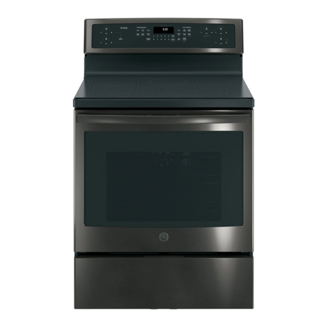
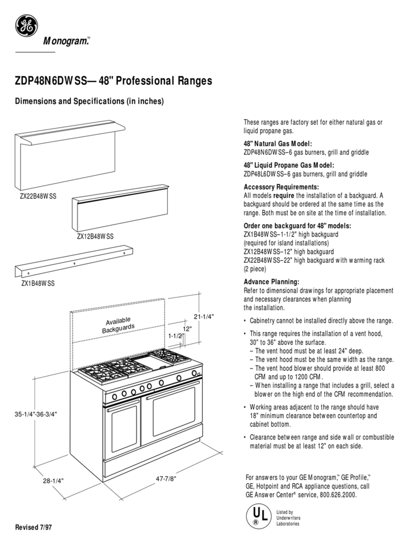
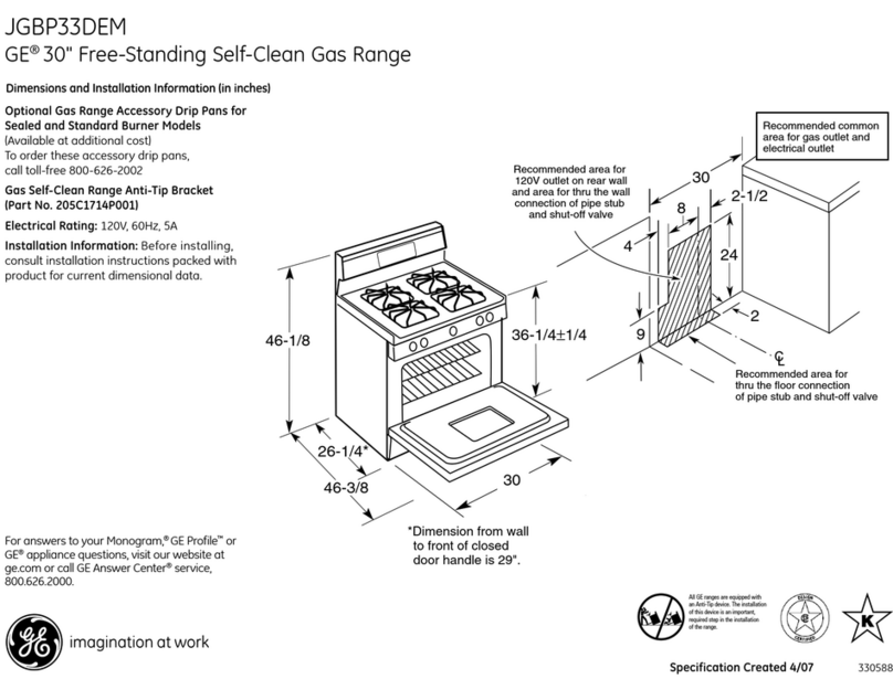
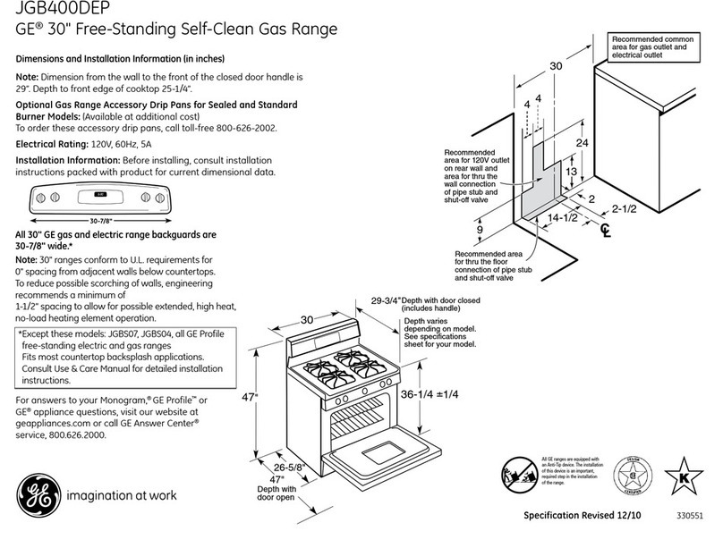
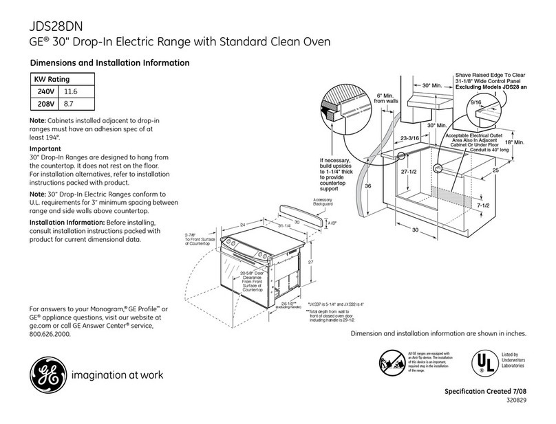
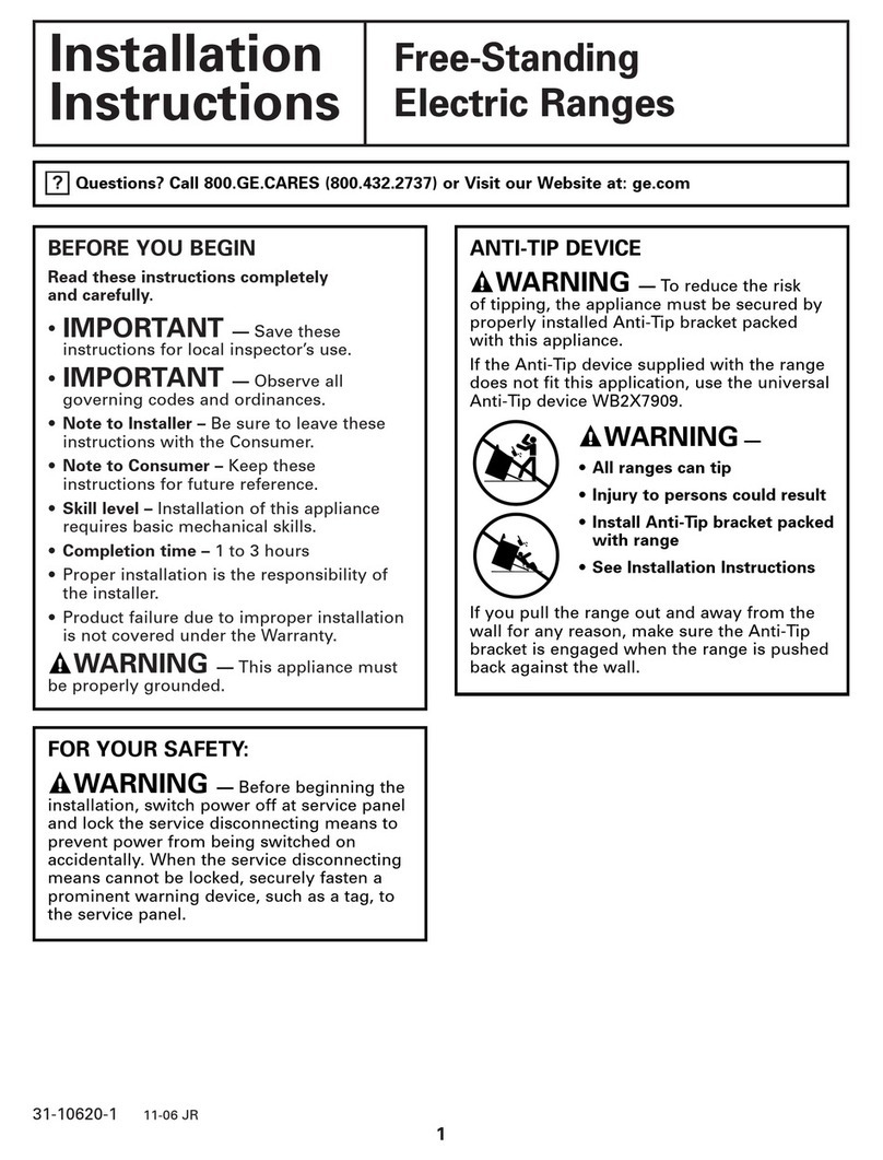
GE PD900 User manual

1
Before You Begin
Read these instructions carefully and completely.
•IMPORTANT—Savethese
instructions for local inspector’s use.
•IMPORTANT—Observeall
governingcodesandordinances.
•NotetoInstaller—Besuretoleavethese
instructions with the consumer.
•NotetoConsumer—Keepthese
instructions for future reference.
•Properinstallationistheresponsibility
of the installer and product failure due
toimproperinstallationisNOTcoveredunder
the warranty.
•NOTE—Thisappliancemustbeproperly
grounded.
•ATTENTIONINSTALLER
Allelectricdrop-inrangesmustbehardwired
(directwired)intoanapprovedjunctionbox.A
plug and receptacle is NOT permitted on these
products.
Ifyouhavequestions,call1.800.GE.CARESorvisitourwebsiteat:
GEAppliances.com
Self-CleaningRadiant
ElectricDrop-InRange
Installation
Instructions JDP47, JD968, JD900, PD900, PD968
Materials Needed
Junction Box Wire NutsStrain Relief Clamp for
1/2” conduit
Parts Included
Lower Trim
4 Screws
2 Shoulder Screws (for
stop device)
Tools You Will Need
1/8” Drill Bit and Electric
or Hand Drill
Phillips Screwdriver
Nut Driver
Level
Tape Measure
Straight Edge
or Square
Hand or Sabre Saw
Standard Screwdriver
Pencil
Safety Glasses
Hammer
31-10622-3 02-10

2
IMPORTANTSAFETYINSTRUCTIONS
Installation Instructions
ForYourSafety
•Allrough-inandspacingdimensionsmustbe
met for safe use of your range.
•Toreducetheriskofburnsorrewhen
reaching over hot surface elements, cabinet
storagespaceabovethecooktopshouldbe
avoided. If cabinet storage space is to be
providedabovethecooktop,theriskcanbe
reducedbyinstallingarangehoodthatsticks
out at least 5” beyond the front of the cabinets.
Cabinetsinstalledabovethecooktopmustbe
no deeper than 13”.
•Besureyourapplianceisproperlyinstalledand
groundedbyaqualiedtechnician.
We recommend you have the electrical wiring
andhookupofyourrangeconnectedbya
qualiedelectrician.Afterinstallation,havethe
electrician show you where your main range
disconnect is located.
Checkwithyourlocalutilitiesforelectricalcodes
which apply in your area. Failure to wire your
range according to governing codes could result
in a hazardous condition. If there are no local
codes, your range must be wired and fused to
meet the requirements of the National Electrical
Code,ANSI/NFPANo.70–LatestEdition.Youcan
get a copy by writing:
NationalFireProtectionAssociation
BatterymarchPark
Quincy,MA02269
EectiveJanuary1,1996,theNational
Electrical Code requires that new, but not
existing, construction utilize a four-conductor
connection to an electric range. When installing
an electric range in new construction, a mobile
home, recreational vehicle or an area where
local codes prohibit grounding through the
neutral conductor, follow the instructions in the
sectiononNEWCONSTRUCTIONANDFOUR-
CONDUCTORBRANCHCIRCUITCONNECTION.
Youmustuseathree-wire,single-phase
A.C.208Y/120Voltor240/120Volt,60hertz
electrical system. If you connect to aluminum
wiring, properly installed connectors approved
for use with aluminum wiring must be used.
WARNING:Forpersonalsafety,
removehousefuseoropencircuit
breakerbeforebeginninginstallation.
Failuretodosocouldresultinserious
injuryordeath.
Rating Plate
Location
Electrical
Requirements
This appliance must be supplied with the
proper voltage and frequency, and connected
to an individual, properly grounded branch
circuit,protectedbyacircuitbreakerorfuse
having amperage as noted on rating plate.
(Rating Plate is located behind the oven door
on the range.)

3(Continued on following page)
Door removal is not a requirement for
installation of the product, but is an added
convenience. To remove the door:
Open the oven door as far as it will go.
Push both hinge
locksdowntoward
the door frame,
totheunlocked
position. This may
requireaatblade
screwdriver.
NOTE:Theovendoorisveryheavy.
Besureyouhavearmgripbeforeliftingthe
ovendoorothehinges.Usecautiononcethe
doorisremoved.Donotlaythedooronits
handle. This could cause dents or scratches.
Installation Instructions
Pre-InstallationChecklist
Hinge Lock
(Unlocked
Position)
Hinge
Slot
Hinge Arm
Place hands on both sides of
the door, and close the oven
door to the removal position.
This is half way between the
broil stop and fully closed.
Lift door up and
out until the
hinge arms
clear the slots.
DONOTLIFTTHEDOOR
BYTHEHANDLE!
InspectInstallationLocation
Protectthekitchenoor! Flatten and place
a piece of the shipping carton in front of the
installationlocationtoprotecttheooring.
MoveRangeIndoorsInFrontof
CabinetOpening
(Donotusehandtruckswhenmoving
theunpackagedrange.Cooktopglass
maybebroken.)
To obtain Kits:
a.VisitGEWebSite(Seepage1)
b.CallGEAnswerCenter(Seepage1)
c. Contact Dealer
Donotremovetheprotectivechannel
fromthesidesoftheglasscooktopuntil
later in installation.
(If supplied)
Inspect cutout dimensions and location
ofelectricaljunctionboxtobesureitts
within the layout location. See page 4.
Refer to alternate construction section for
the following non-standard installations.
a.
Counteropeningextendstothewall:
Maintop Filler Kit (JXS66XX), or
BackguardKit(JXS36XXorJXS39SS).
WARNING:If you do not use these
kits,theanti-tipbracketmusttunder
an attachment to the wall that can
withstand a force of 200lbs. in the
upward direction. See Section D1.
b. IslandInstallation:
To provide an optimum installation, the
top surface of the countertop must be
levelandat(lieonthesameplane)
around the 3 sides that are adjacent to
rangecooktop.Properadjustmentsto
makethetopatshouldbemadeor
gaps between the countertop and range
cooktopmayoccur.Forcingthecooktop
totmaycauseexcessivegaps,orcould
breaktheglasscooktopandvoidthe
warranty.
Removepackingmaterials.Removelabels
on door, plastic on trims and
panel, and all tape around the range.
Hinge
Clears Slot

4
Installation Instructions
NOTE:Drop-InRangesaredesignedtohang
fromthecountertoponly.Donotinstallon
a platform or support rails.
Pre-InstallationCutoutandRequired
Clearances
A
If cabinets are placed less than
30” min. above the range, see
alternate construction.
30” ranges conform to U.L.
requirements for 0” spacing from
vertical walls below countertops.
Allow1/4”minimumclearance
atthebackwallabovethe
countertop.
Wall coverings, counters and
cabinets around range must
withstand heat (up to 194°F)
generated by the range.

5
Installation Instructions
The Standard Installation of this Drop-In
Range is to hang by the countertop on the
sidemetalangesunderglasscooktop.
ThisRangemustnotbeinstalledona
baseorsubstructure(2”x4”support).
If the construction of your cabinet cannot
providea1/4”atareaatthebackofthe
countertop opening, consider changing the
countertop to accommodate this dimension.
Iftheareaisnotat,excesstensionmay
beappliedtotheglasscooktop,causing
breakageandvoidingthewarranty.
Center the 30” wide opening over the ad-
jacentcabinetsandmarkwithastraight
edge.
Usingastraightedge,markthebacklineat
23-3/16” from the front edge of the counter.
Be careful not to damage the adjacent
cabinets while cutting the countertop.
Remove countertop raised edge, if
incorporated. (See illustration on page 4)
StandardInstallationPreparation
B
B1
B2
B3
B4
STANDARDINSTALLATION
Wall
1/4”Min.
Flat
23-3/16”
9/16”Min.
Flat
9/16”Min.
Flat
29-15/16”–30-1/16”
SmoothCut
25”Typically
1/4”
R
Flat
Area
Countertop
RangeSupport
Bracessecuredbetweenthe
underside of the countertop and
thecabinetifrequiredtoobtain
1-1/4”minimumthickness(two
sides)

6
Remove house fuse or open circuit
breaker.
Loosen screws for the junction box cover
and rotate out of place or remove the
cover.
Examine the junction box location to
determine the best routing of the conduit,
and select the best available
7/8”diameterknockout.Avoidusing
holes in the top of the junction box to
prevent the conduit from interfering
withthebackoftherange.
Breakopentheselectedknockoutby
placing a bladed screwdriver on the
scored opening in the junction box and
strikingthescrewdriverwithahammer.
(Pliers may be required to complete the
removaloftheknockout.)
Installation Instructions
GENERALNOTEFORALLWIRENUT
APPLICATIONS:THEPROPERSIZEWIRENUT
SHALLBEPLACEDOVERTHESTRIPPEDLEADS
ANDTHEWIRENUTTWISTEDUNTILTHEWIRE
NUTCANNOTBEPULLEDFROMTHELEADS.
NOCONDUCTORSHALLBEEXPOSEDIN
THECONNECTION.THEEXCEPTIONTOTHE
CONDUCTORBEINGEXPOSEDISTHEBARE
COPPERGROUNDCONNECTION.
Position the range in front of the opening,
but slightly to the side, in a manner so
that a person can enter the opening to
wire the range to the house wiring in the
junction box.
Feed wires and conduit through the open
holeandsnaptheconduitttingintothe
hole. Route the conduit in a manner that
will not interfere with the rear wire cover.
The conduit must be routed below the
wire cover.
BREAKERORFUSESIZE
240V 40Amps+
208V 40Amps+
+NOTE:CheckLocalCodesfor
requiredbreakersize.
ElectricalConnections
C
C1
C2
C3
C4
C5
C6
WARNING:
Improper
connection of aluminum house
wiring to copper leads can result in
anelectricalhazardorre.Useonly
connectorsdesignedforjoiningcopperto
aluminum and follow the manufacturer’s
recommended procedure closely.
(Continued on following page)
7/8”Knockout
CoverRotatedFrom
BoxOpening

7
Installation Instructions
THREE-CONDUCTORBRANCH
CIRCUITCONNECTION
When connecting to a 3-conductor branch cir-
cuit, if local codes permit:
Connect the bare oven ground
conductor with the crimped neutral
(white) lead to the branch circuit
neutral (white or gray in color),
using wire nuts.
Connect the oven red lead to the branch
circuitredlead,andtheovenblack
leadtothebranchcircuitblackleadin
accordance with local codes, using wire
nuts.Iftheresidencered,blackorwhite
leads are aluminum conductors, see
“WARNING”note
(See page 6).
ElectricalConnectionscont.
C
C7a
C7b
NEWCONSTRUCTIONAND
FOUR-CONDUCTORBRANCHCIRCUIT
CONNECTION
•Wheninstallinginnewconstruction,or
•Wheninstallingoveninamobilehomeor
recreational vehicle, or
•Whenlocalcodesdonotpermitgrounding
through neutral:
Cut the neutral (white) lead from the
crimp. Re-strip the neutral (white)
lead to expose the proper length of
conductor and connect it to the white or
gray branch circuit neutral in accordance
with local code using wire nuts.
Attachtheappliancegroundinglead
(green or bare copper) in accordance
with local codes. If the residence
grounding conductor is aluminum,
seeWARNINGnote(Seepage6).
Connect the oven red lead to the
branch circuit red lead and the oven
blackleadtothebranchcircuitblack
lead in accordance with local codes,
using wire nuts. If the residence red,
blackorwhiteleadsarealuminum
conductors,see“WARNING”note
(See page 6).
C7a
C7b
C7c
(Continued on following page)
Branch
Circuit
Black
Alternate
Knockout
Neutral Bare Wire
Connection
RangeConduit
SnapsIntoBox
Red
Groundand
Neutral Wires
(White)
Branch
Circuit
Black
Alternate
Knockout
RangeConduit
SnapsIntoBox
Red
White
Ground
Wires

8
Installation Instructions
Donotshortentheexibleconduit.Theconduitstrainreliefclampmustbesecurelyattachedto
thejunctionboxandtheexibleconduitmustbesecurelyattachedtotheclamp.Iftheexible
conduitwillnottwithinthejunctionbox,donotinstalltheovenuntilaclampofthepropersize
isobtained.
NOTETOELECTRICIAN: The 3 power leads supplied with this appliance are UL recognized
for connection to larger gauge household wiring. The insulation of these 3 leads is rated at
temperatures much higher than the temperature rating of household wiring. The current carrying
capacity of the conductor is governed by the temperature rating of the insulation around the wire,
rather than the wire gauge alone.
ElectricalConnectionscont.
C
Reinstall Junction box cover.
C8

9
Installation Instructions
Select the proper position for the countertop
thicknessandmovebrackettoproperposition.
(Unitissuppliedwithbracketinposition1.)
StandardInstallationInstructions
D
InstallingtheAnti-TipBracket
Theanti-tipbracketisattachedto
thebackoftheDrop-InRange.Itis
designedtotunderthebottomofthe
countertop opening at the rear. Measure
counterthicknessatbackofcutoutto
determinecorrectbracketlocation.
D1
(Continued on following page)
1 For 3/4” Counter
2 For 1.18” (3 cm) Counter
3 For 1.5” Counter
4 For 3.5”
5Alternate
(shown below)
ANTI-TIPINSTALLATION
ALTERNATE
ANTI-TIPINSTALLATION
Interior Wall
1/4”Min.FlatArea WallStud
Countertop
Thickness
Bottom of
Countertop
WireCover
Glass
Maintop
Anti-Tip
Bracket
Bottom of
Countertop
toEngage
Bracketby
1/2”Min. WallStud
10-3/8”
1-1/2”
Countertop
Surface
Interior Wall
Wire
Cover
Attachment
Anchored To
WallStudIs
Required
Anti-TipBracket
Attachment
Non-KitApplication
GlassMaintop
Position #5
Non-KitAp-
plication
*Attachment
ToEngage
BracketBy1/2”Min.
Anti-TipBracketLocation
(Rear of Range)
GlassCooktop

10
Installation Instructions
(Continued on following page)
StandardInstallationInstructionscont.
D
Carefullymarkthecabinetforthe
location of the stop screws. Drill 1/8”
pilot holes into the cabinet, each side of
therange.(Makesurenottodrillentirely
through the cabinet wall.) Carefully turn
the shoulder screws into the pilot holes
until they are tight.
InstallStopScrew
These screws prevent the range from
sliding out of position during operation.
Placing the Range into the
Opening(Continued)
D2 D3
Placing the Range into the
Opening
It is suggested that two people lift the
range into place, carefully setting the
sidemetalangesundertheglasson
the edges of the countertop opening.
The protective channels must be in
place (if supplied) during this operation.
D3
Countertop
Cabinet
Range
LiftandSlideRange
onCountertop
Countertop
GapApprox.4”
GapApprox.4”
RemovetheProtectiveChannels
(ifprovided)
Carefully remove the protective channels
fromthesidesoftheglasscooktop.This
may require a slight lifting of the range to
remove the weight of the range from the
protective channels.
D4
RemoveProtectiveCoverFrom
BothSidesAfterRangeIsInCabinet
ProtectiveCover
GlassCooktop
Carefullyslidetherangetowardthebackofthe
opening. Stop pushing the Range when there
isstilla4”gapatthefrontbeforeushingthe
Range with the countertop.

11
Installation Instructions
StandardInstallationInstructionscont.
D
CheckForProperInstallationof
theStopScrew
Lookatbothsidesoftherangeunderthe
door. The stop screws must be located in
the notch on the sides of the range, and
not touch the top of the notch when the
range is fully seated on the countertop. If
the screws do not meet the requirements,
move the screws to a position that meets
these requirements.
(See illustration below.)
D7
(Continued on following page)
LocatingtheStopScrew
It is suggested that two people lift the
range and carefully slide it towards the
backoftheopening.Whentherange
isapproximately1”fromthebackof
the opening, lift the front of the range
approximatley 1/2” to clear the stop screw
located in the sides of the cabinet. Slide
the range until the range is seated into the
opening.
Lower the front of the range onto the
countertop.
D6
AttachtheLowerTrim
Attachthelowertrim(suppliedseparately
with the range) to the bottom of the
vertical side trim with the 4 screws
supplied.
D5
Lower
right end
of front
frame
Lower
trim
Side trim
Clear
Notch in bottom
of side trim
Shoulder screw
Lower
trim
Attach2
screws
each side

12
Installation Instructions
Lift the oven door by
placing one hand on
each side. The door is
heavy, so you may need
help. Do not lift the door
by the handle.
With the door at the same angle as
the removal position (halfway between
the closed and broil stop position,
seat the notch of the hinge arm into
the bottom edge of the hinge slot.
The notch of the hinge arm must be
fully seated into the bottom of the slot.
Pushthehingelocksupagainstthe
front frame of the oven cavity, to the
lockedposition.
Close the oven door.
StandardInstallationInstructionscont.
D
NOTE:
Theovendoorisheavy.Youmay
need help lifting the door high enough to
slideitintothehingeslots.Donotliftthe
doorbythehandle.
D8
D9
BottomEdge
ofSlot
HingeArm
HingeNotch
NotchofHinge
SecurelyFittedinto
BottomofHinge
Slot
Hingein
LockedPosition
ReplacingtheOvenDoor
Open the oven door as far as it
will open.
D11
D12
CheckforProperInstallationof
Anti-TipBracket
Lower the oven door and gently apply
medium force at the handle end until
movement of the range is detected. Con-
tinuepressinguntiltheanti-tipbracketis
engagedandmovementstops.Asmall
amount of movement is acceptable at
thebackoftherangetop,butitshould
be stable and not tip once the anti-tip
bracketisengaged.
D13
D10

13
Installation Instructions
Checktomakesurethecircuitbreakerisclosed(Reset)orthecircuitfusesarereplaced.
Be sure power is in service to the building.
Checktobesurethatallpackingmaterialsandtapeonmetalpanel(ifapplicable)under
controlknobsanddrawerhavebeenremoved.
FinalChecklist
ChecktomakesuretheClockdisplayisenergized.Ifaseriesofhorizontalredlinesappearin
thedisplay,disconnectpowerimmediately.Rechecktherangewiringconnections.Ifchange
ismadetoconnections,retestagain.Ifnochangeisrequired,havebuildingwiringchecked
forproperconnectionsandvoltage.Itisrecommendedthattheclockbechangedifthered
lines appear.
Pushdownandturnanyoneofthefoursurfaceknobsto“MED”settingtoobservethatthe
elementglowswithin15seconds.Turntheknobowhenglowisdetected.Iftheglowisnot
detectedwithinthetimelimit,rechecktherangewiringconnections.Ifchangeisrequired,
retestagain.Ifnochangeisrequired,havebuildingwiringcheckedforproperconnections
and voltage.
OperationChecklist

14
Installation Instructions
AlternateConstructionPreparation
RefertotheFillerorBackguardKit
instructions for Installation details.
OptionalMaintopFillerorBack-
guardKit
If counter opening extends to the wall, it will
requireMaintopFillerKit(JXS66XX)orBack-
guard Kit (JXS36XX or JXS39SS) to close the
gap.
NOTE: If the countertop is greater than 25”,
itwillshowagapbetweenthebackguard
andwallorbetweenllerkitandthewall.
If the countertop is less than 25”, a gap will
occur between the countertop front and the
control panel ends.
(Seepage10,D3).
AA Island Installation
When installing in an island or other
non-standard location, countertop cutout
dimensions must be according to page 5.
Fortheanti-tipbracketinstructions,see
page 9.
Inthisapplication,donotuseBackguardKit
(JXS36XX or JXS39SS).
AB
CabinetsOverTheRange
LessThan30”
Ifa30”clearancebetweencookingsurface
and overhead combustible material or
metal cabinets cannot be maintained,
protect the underside of the cabinets
abovethecooktopwithnotlessthan1/4”
insulating millboard covered with sheet
metalnotlessthan0.0122”thick.
AC
Wall
Must Be
Flat
Must Be
Flat
Must Be
Level
MustBeLevel
30”
SmoothCut
9/16”9/16”
25”

15
NOTES

16
NOTES
31-10622-3
02-10 GE
This manual suits for next models
14
Table of contents
Other GE Range manuals