Installation
Refrigerator
Instructions Models 20 and 22
Questions? Call 800.GE.CARES (800.432.2737) or Visit our Website at: ge.com
In Canada, call 1.800.361.3400 or Visit our Website at: www.geappliances.ca
BEFORE YOU BEGIN
Read these instructions completely
and carefully.
•IMPORTANT —Save these
instructions for local inspector’s use.
•IMPORTANT —Observe all
governing codes and ordinances.
•Note to Installer – Be sure to leave these
instructions with the Consumer.
•Note to Consumer – Keep these
instructions for future reference.
•Skill level – Installation of this appliance
requires basic mechanical skills.
•Completion time – Refrigerator Installation
20 minutes
Water Line Installation
30 minutes
•Proper installation is the responsibility of
the installer.
•Product failure due to improper installation
is not covered under the Warranty.
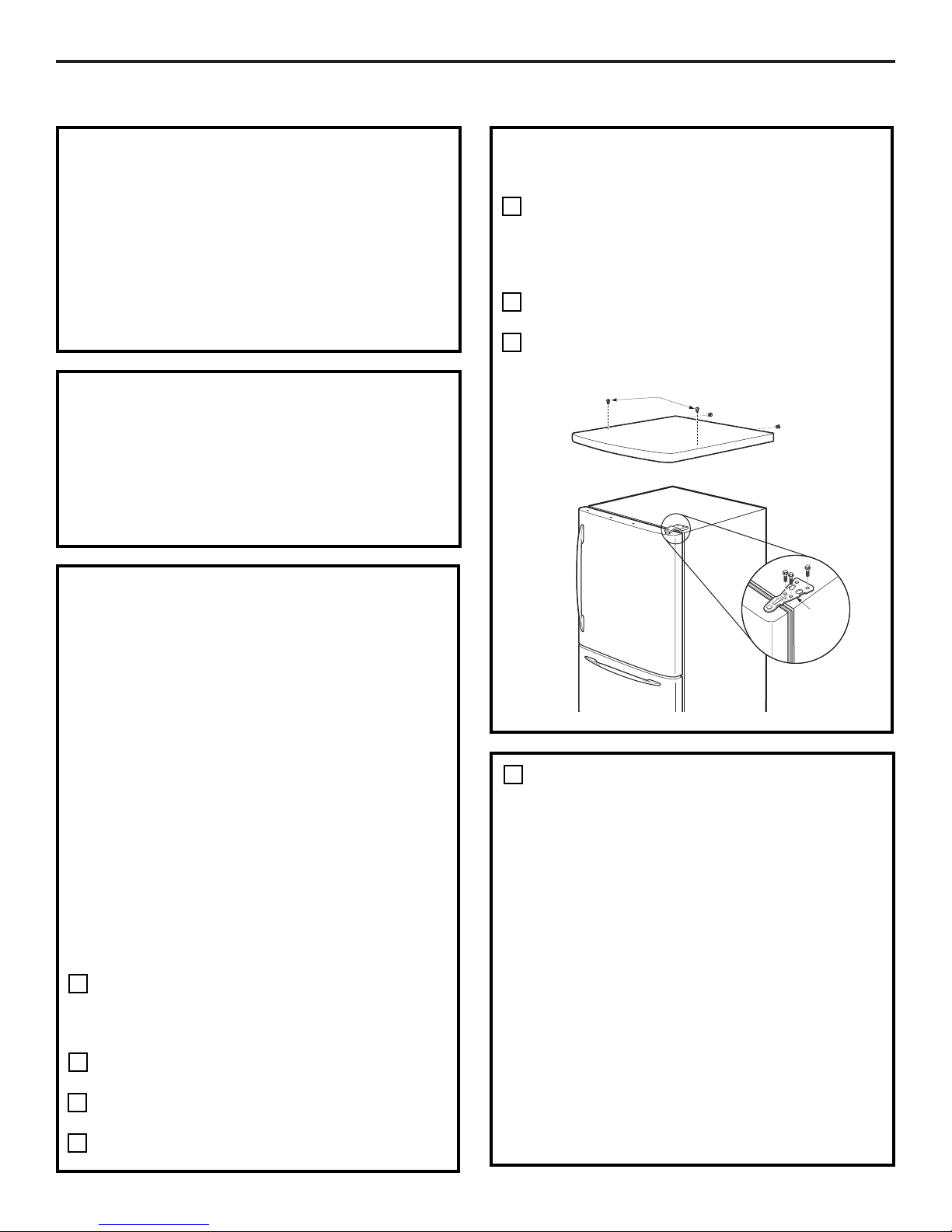
PREPARATION
MOVING THE REFRIGERATOR INDOORS
If the refrigerator will not fit through a doorway,
the refrigerator door and freezer drawer or door
(depending on model) can be removed.
•To remove the refrigerator door, see Step 1
in the Reversing the Door Swing section.
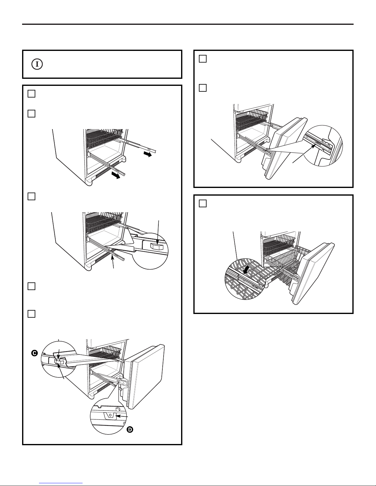
•To remove the freezer drawer, see the
Removing the Freezer Drawer section.
•To remove the freezer door, see Steps 2
and 3 in the Reversing the Door Swing
section.
PREPARATION (cont.)
WATER SUPPLY TO THE ICEMAKER AND
DISPENSER (ON SOME MODELS)
If the refrigerator has an icemaker, it will have
to be connected to a cold water line. A GE water
supply kit (containing tubing, shutoff valve,
fittings and instructions) is available at extra
cost from your dealer, by visiting our Website
at ge.com (in Canada at www.geappliances.ca)
or from Parts and Accessories, 800.626.2002 (In
Canada 1.888.261.3055).
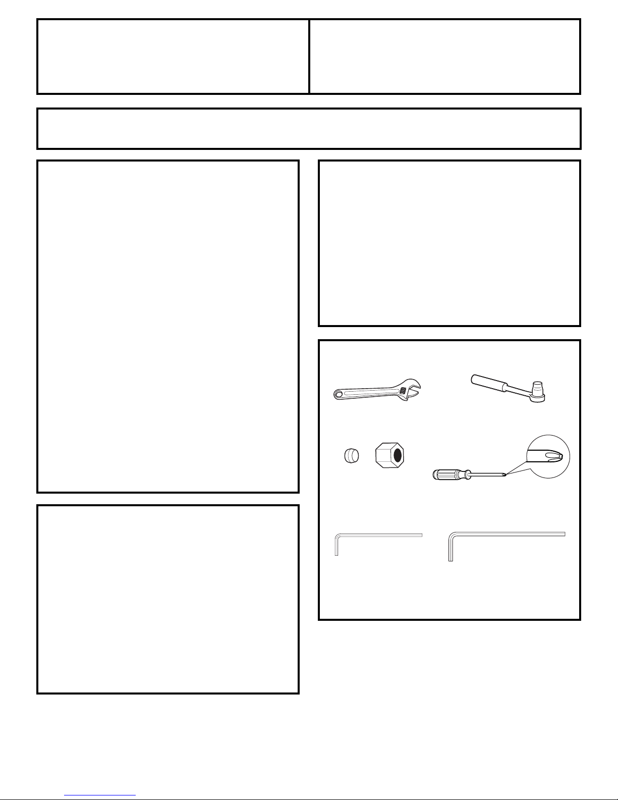
TOOLS YOU MAY NEED
Adjustable Wrench
1/4″Outer Diameter
Compression Nut
and Ferrule (sleeve)
(icemaker models only)
Phillips Head Screwdriver
16
3/8″ and 10 mm Socket
Ratchet/Driver
3/32″Allen wrench
supplied for use on
Stainless steel
refrigerator handles
(on some models)
1/4″Allen wrench supplied
for changing handle
fasteners location
(on some models)