– 7 –
Throughout this manual, features and appearance may vary from your model.
Control Features
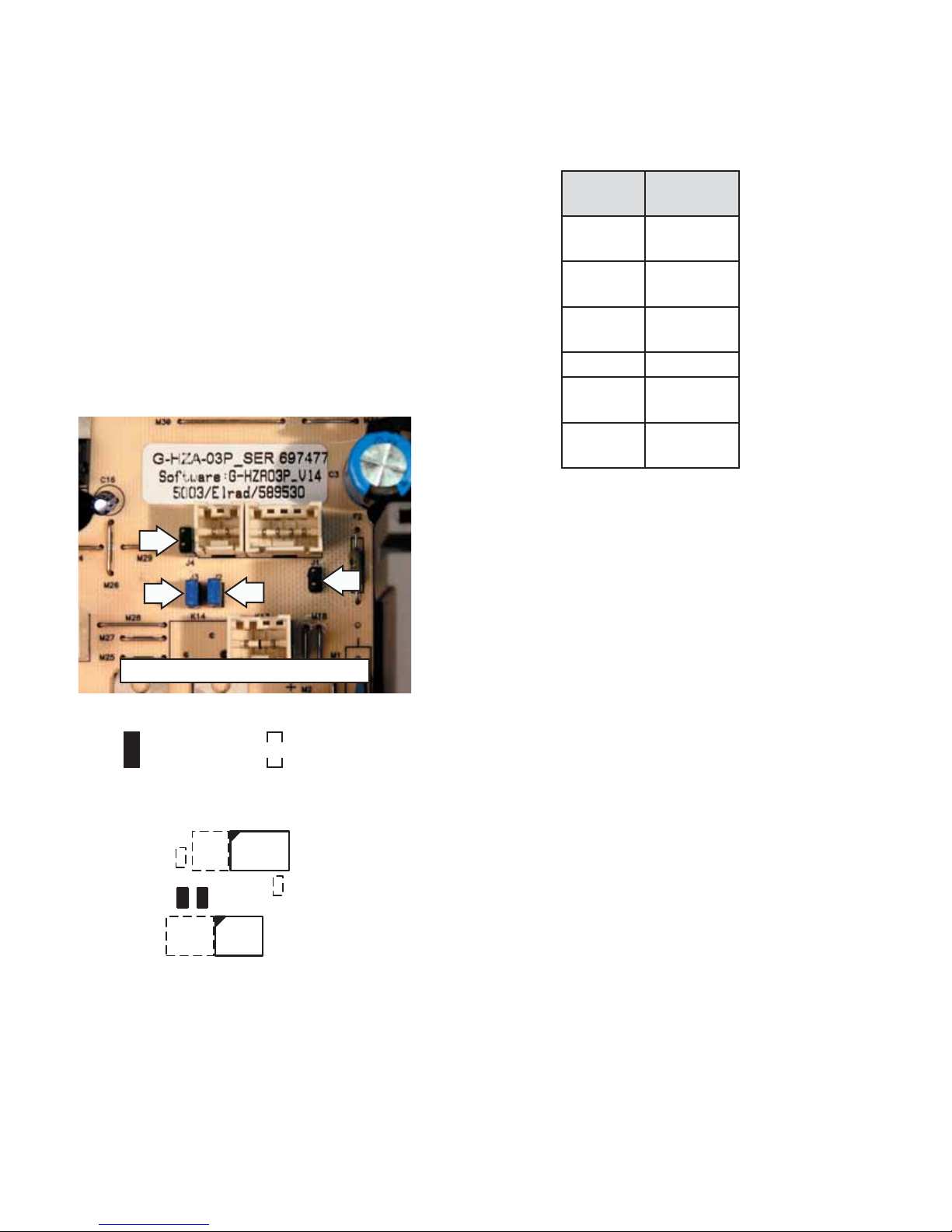
Temperature Control
Factory Settings Control Range
38°F 34°F - 45°F
The temperature display shows the actual
temperature of the refrigerator. The actual
temperature may vary slightly from the set
temperature based on factors such as door
opening, amount of food, and room temperature.
To change the temperature setting, press the
WARMER or COLDER pads until you reach the desired
set temperature. After 5 seconds, the display will
return to the actual temperature. Allow 12 to 24
hours for the refrigerator to reach the temperature
you have set.
Child Control Lockout
The child control lockout feature prevents
unwanted changes to the temperature settings.
After the desired temperature is set, the
temperature can be locked. To lock, press the
+and -pads simultaneously for 5 seconds. To
unlock, press both pads simultaneously again for
5 seconds.
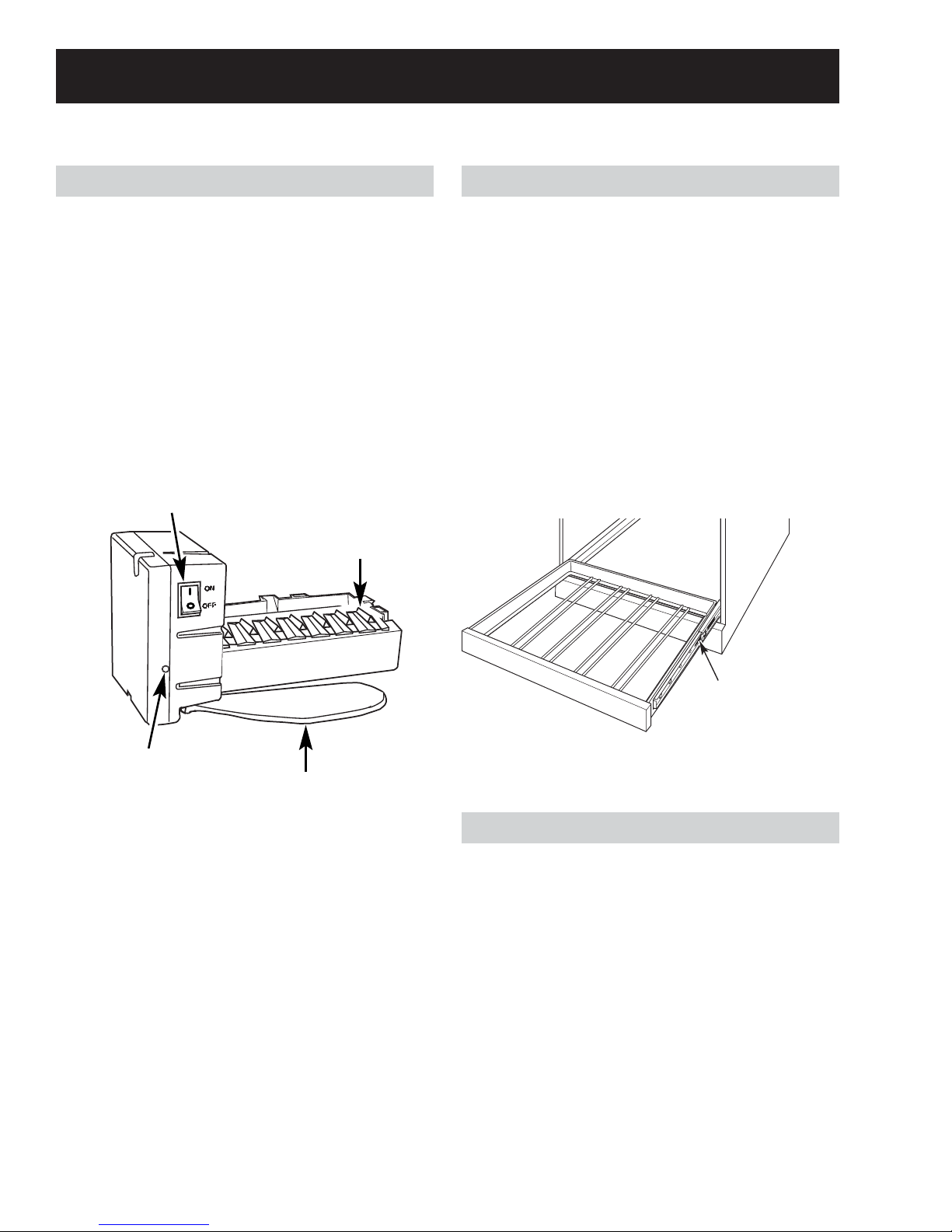
Refrigerator ON/OFF
This pad stops cooling in the refrigerator, turns off
the temperature controls, and removes power to
the light circuit.
Press this pad for a minimum of 3 seconds to
turn the refrigerator OFF for long
vacations or absences, or when
cleaning the unit or changing the
light bulb. Press the pad again to
turn the refrigerator ON.
Cleaning the Outside
Door Handles and Trim
Clean with a cloth dampened with soapy water.
Dry with a soft cloth. Keep the outside clean.
Wipe with a clean cloth lightly dampened with
mild liquid dish detergent. Dry with a clean, soft
cloth. Do not wipe the refrigerator with a soiled
dish cloth or wet towel. These may leave a
residue that can damage the finish. Do not use
scouring pads, powdered cleaners, bleach or
cleaners containing bleach, these products can
scratch and damage the finish.
Stainless Steel
To preserve and protect the fine finish, regularly
clean and polish the stainless steel exterior and
handle with a commercially available stainless
steel cleaner, such as Stainless Steel Magic™.
Stainless Steel Magic™ is available through GE
Parts and Accessories, 800.626.2002 or GE
Appliances.com. Order part number WX10X15.
To avoid damaging the stainless steel, wipe in
the same direction as the grain when polishing or
cleaning any stainless steel surface. Do not use
appliance wax or polish on the stainless steel.
Warranty does not cover damage due to improper
cleaning methods.