GR
OUND
20
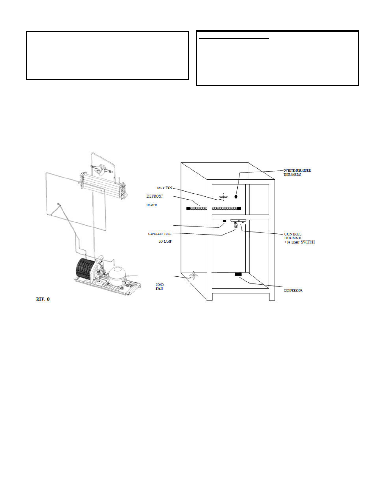
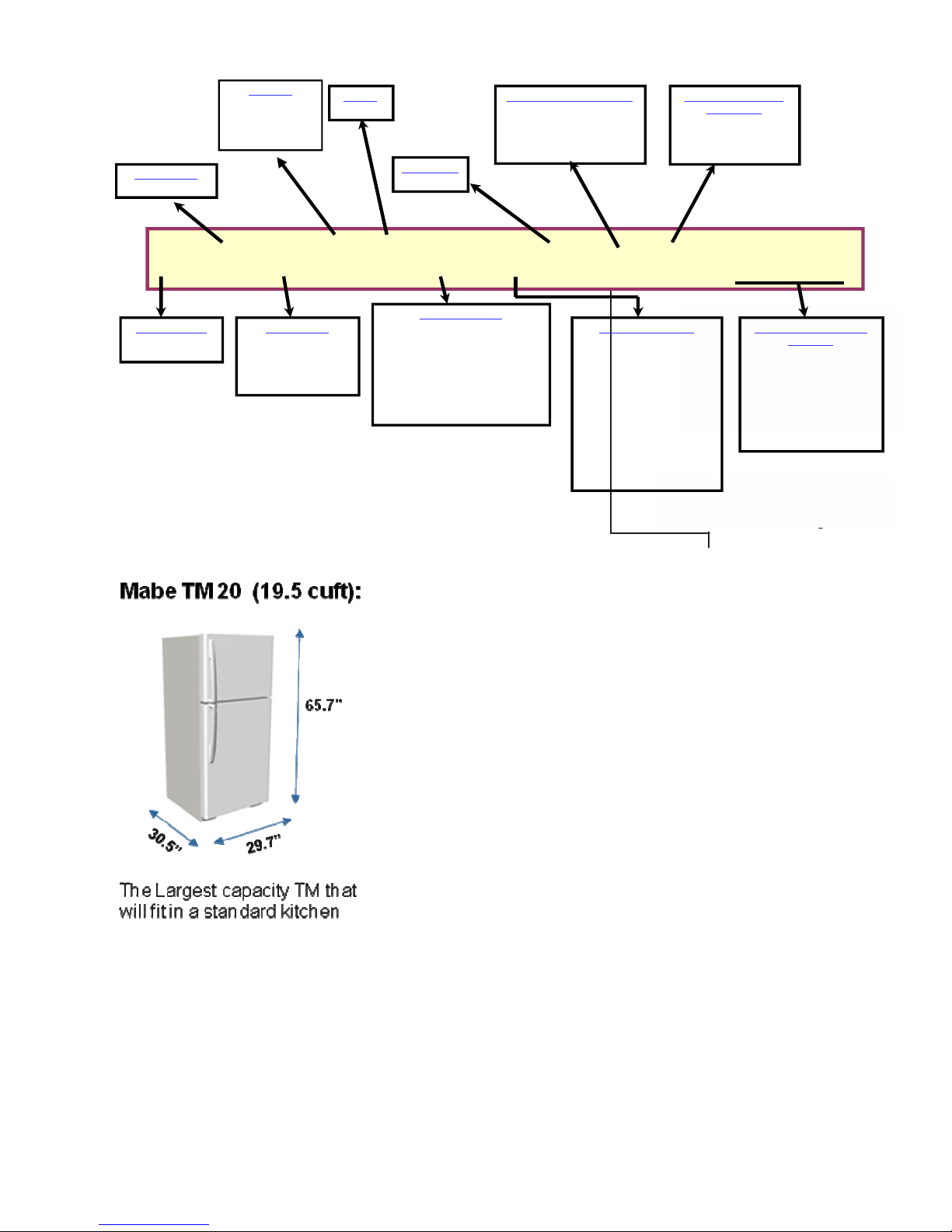
TOP MOUNT GE™
ELECTRONIC
DISCONNECT POWER CORD BEFORE
SERVICING
T
echnical
Data
IMPORTANT SAF
ET
N
O
TICE
238C4518P002
IMPORTANT
-
RECONNECT ALL
GROUNDING
D
E
VICES
All
parts of this
appliance capable
of conducting
electrical
cur-
rent are grounded.
If
grounding wires,
sc
r
ews,
straps,
clips, nuts
or
washers
used to complete a path
to
ground are r
emo
ed
for ser ice, they must be
returned
to their original position and
properly
fastened.
ELECTRICAL
SPECIFIC
A
TIONS
T
emperatu
r
e
Control
(
P
osition FF/FZ)
...................................................
37/0°F
Defrost Control (w/no door openings)
.............................
96hrs @ 35 min
Thermistor kilo-ohm r
esistance
.............................................
@0°F
..........
42.7
.............................................................................................................
@37°F
..........
14.3
.............................................................................................................
@77°F
.............
5.0
O ertemperature
Thermostat
..............................................................
69-59°F
Defrost Thermistor
.............................................................................................
34°F
Electrical Rating:
115V AC
60 Hz
.....................................................
11.6 Amp
Maximum Current Leakage
..................................................................
0.75 mA
Maximum Ground Path
R
esistance
.............................................
0.14 Ohms
NO LOAD
PERFORMANCE
Control Position 5/5 and Ambient of 70°F to 90°F
Fresh Food, °F
............................................................................................
34
to
40
Frozen Food,
°F
.............................................................................................
-3
to 3F
Run
Time,
%
@ 70°F
..................................................................................
15
to
40
Run
Time,
%
@ 90°F
..................................................................................
30
to
60
This
information is intended for use by indi iduals
possessing
adequate backgrounds
of electrical, electronic
and
mechanical
experience. Any
attempt
to repair a
major
appliance may result
in personal injury and
p
r
ope
r
ty
damage.
The
manufacturer or
seller cannot be responsible for the
interpretation
of
this
informa-
tion, nor can it
assume
any
liability
in
connection
with its
use.
REFRIGERATION
S
STEM
Compressor 20 - 22 Models
..........................................................
803
BTU/hr
Minimum Compressor Capacity
..............................................
22
inches Hg
Minimum Equalized
P
r
essu
r
e
@ 70°F
................................................................................................
40
to
45
PSIG
@ 90°F
.................................................................................................
48
to
60
PSIG
REFRIGERANT
CHA
R
GE
(R134a)
20 models
................................................................................................
4.0
ounces
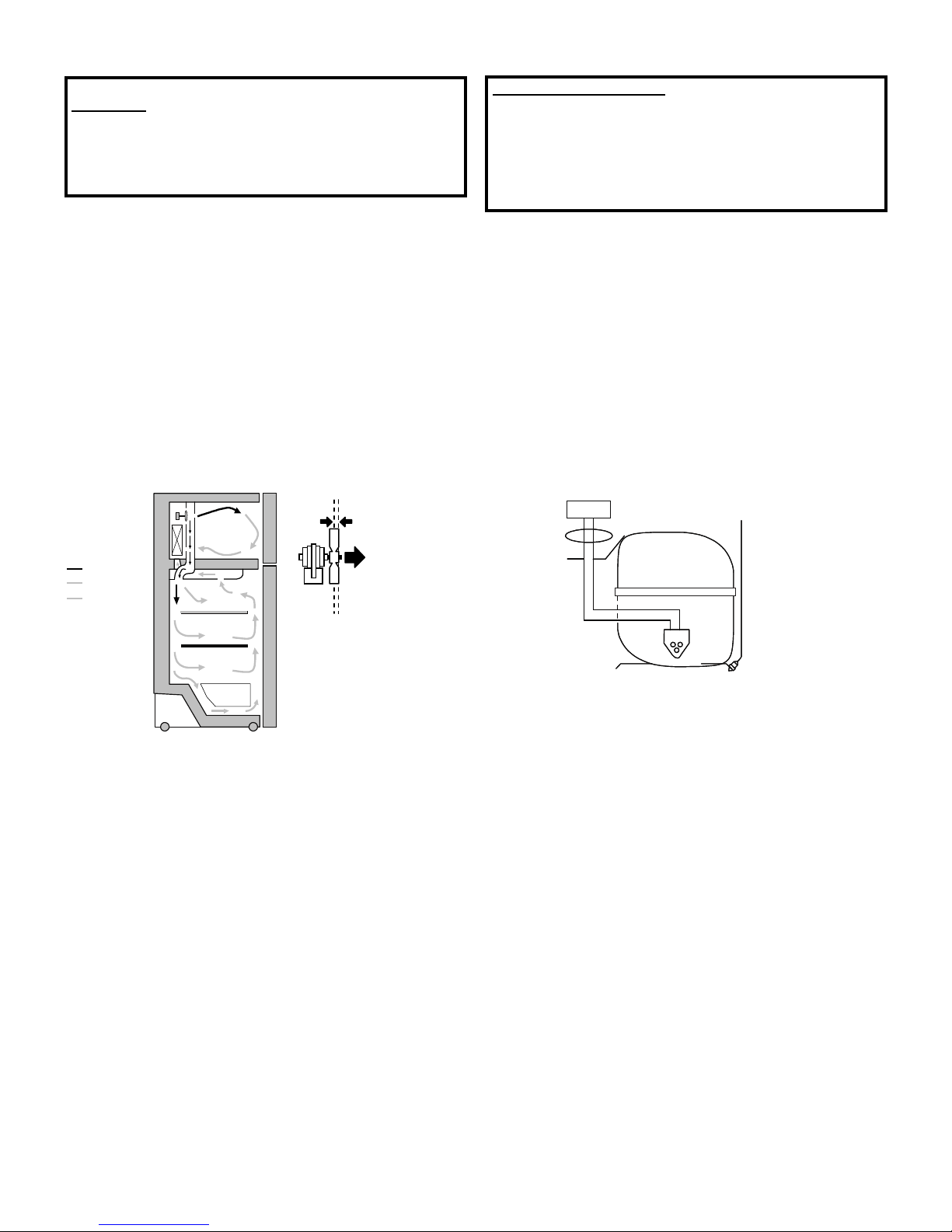
AIR
F
L
OW
E
V
APOR
AT
OR
COLD
AIR
MIXED
AIR
AIR
RE
TURN
T
O
FREEZER
.105”
T
O
CABIN
E
T
WIRING
ORANGE
BLA
C
K
GREEN/YEL
L
O
W
E
V
APOR
AT
OR
FRESH
FOOD
COMPRESSOR