GE Monogram ZICP720 User manual

Installation
Instructions
Professional Stgle
Bottom-Freezer Refrigerators
ZICP720
Design Guide
With Installation Instructions
@Monogram:

Safety Information
BEFOREYOUBEGIN
Readthese instructions completely and carefully.
•INPORTANT-Savetheseinstructionsfor
local inspector's use.Observeall governing codes and
ordinances.
•Note to Installer- Besureto leavethese instructions
with the Consumer.
• Note to Consumer- Keeptheseinstructionswith uour
Owner's Manual for future reference.
WARNING:
Thisappliance must be properlUgrounded.See"Grounding
the Refrigerator,"page 6.
AVERTISSEMENT'.
Cetappareil doit _tre correctement mis 6 la terre.
Consultez<<Mise6 laterre du rdrig@rateur >>,page 6.
If Uoureceiveda damaged refrigerator,Uoushould
immediately contact your dealeror builder.
CAUTION:
Dueto the weight and sizeof this refrigerator,and to reduce
the risk of personalinjurUor damage to the product-THREE
PEOPLEAREREQUIREDFORPROPERINSTALLATION.
PRUDENCE'.
Acausedu poidsetdelatailledecerdrig_ratoretpourr_duire
lerisquedeblessureetdedommages,ILFAUTTROISPERSONNES
POURFAIREL'INSTALLATIONCORRECTEMENT.
SkillLevel- Installation of this refrigerator requires
basic mechanical, carpentru and plumbing skills.Proper
installation isthe responsibilitUof the installer.Product
failure due to improper installation is not covered under
the GEApplianceWarrant U.Seethe Owner's Manual for
warrant Uinformation.
WARNING:
• Theserefrigerators are top-hea% and must besecured
to preventthe possibilitUoftipping forward. Anti-Tip
protection is required.Seepages9 and !0 for details.
• Usethis appliance only for its intended purpose.
ImmediatelUrepair or replace electricservicecords that
become fraued or damaged.
Unplugthe refrigerator beforecleaning or making repairs.
Repairsshould be made bu a qualified servicetechnician.
AVERTISSEMENT'.
• Cesrdrig@rateurssont Iourdsen haut et il faut les
arrimer pour @viterlear basculement. IIfaut avoir un
sgst@mede protection contre lerenversement.Voir
lesd_tails pages9 et !0.
• IIne faut utiliser cet appareilque pour I'utilisation
appropri@e.
• R@parezou remplacezimm@diatementtout cordon
@lectriqueeffiloch@ou endommag@.
• IIfaut d@brancherle rdrig@rateuravant le nettoyage
ou toute intervention.
• Lesr@parationsdoivent@trefaites par un technicienqualifi&
For Monogram local service in gout area,
call 1.800.444.1845.
For Monogram service in Canada, call 1.888.880.3030.
For Monogram Parts and Accessories,call L800.626.2002.
www. monogram.cam
CONTENTS
Planning Guide
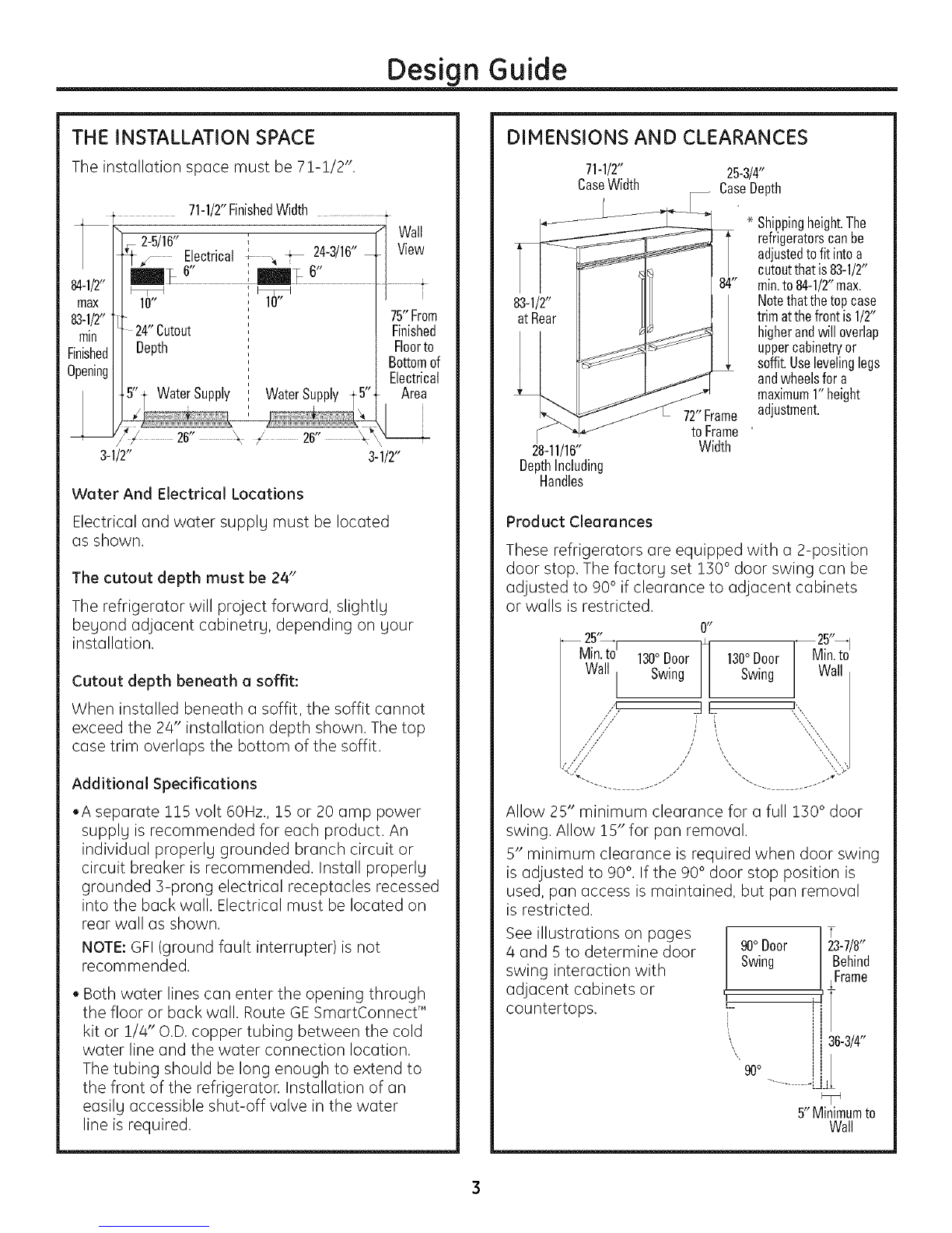
The Installation Space ......................3
Dimensions and Clearances ..........3
!30 ° Door Swing ..................................4
90 ° Door Swing ....................................5
Installation Instructions
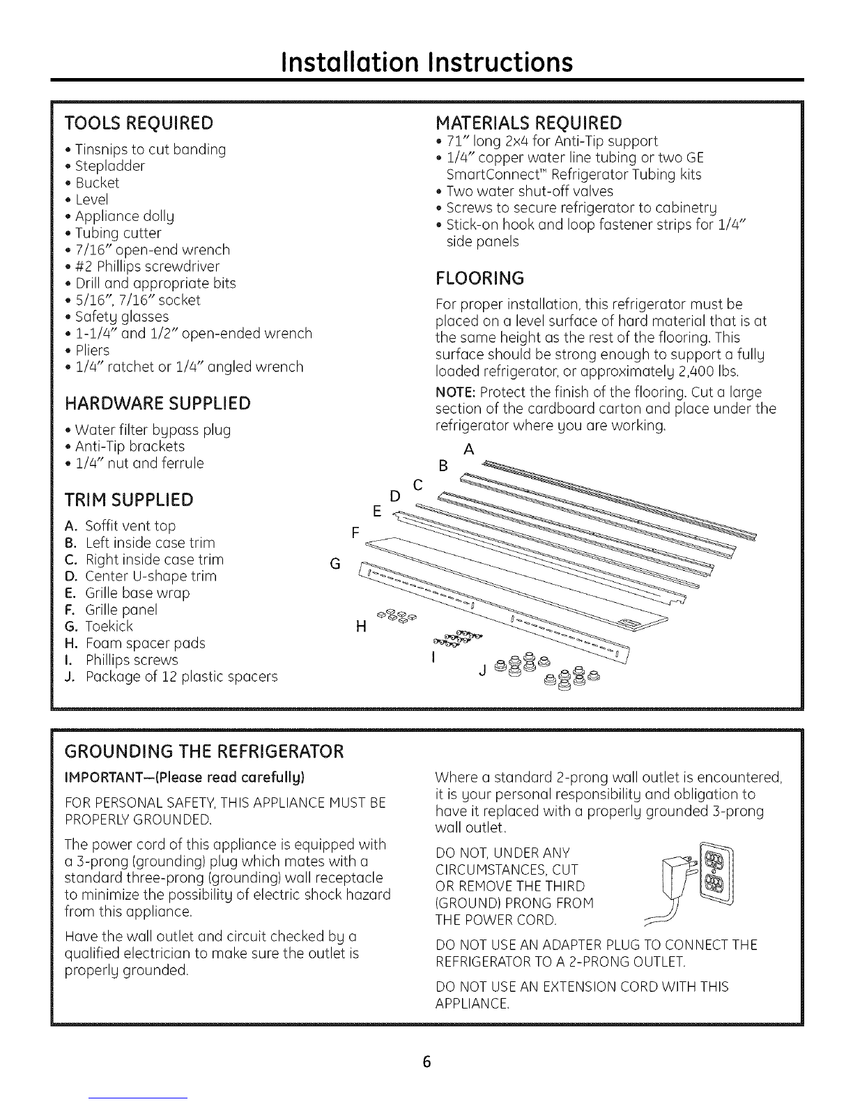
Tools, Hardware, Trim,
Materials, Flooring ..............................6
Grounding the Refrigerator ............6
Step !, Remove Packaging ............7
Step 2, Install Water Lines ..............7
Step 3, Install New Side Trim ..........8
Step 4, Install Side Panels ................8
Step 5, Install Anti-Tip Brackets....9
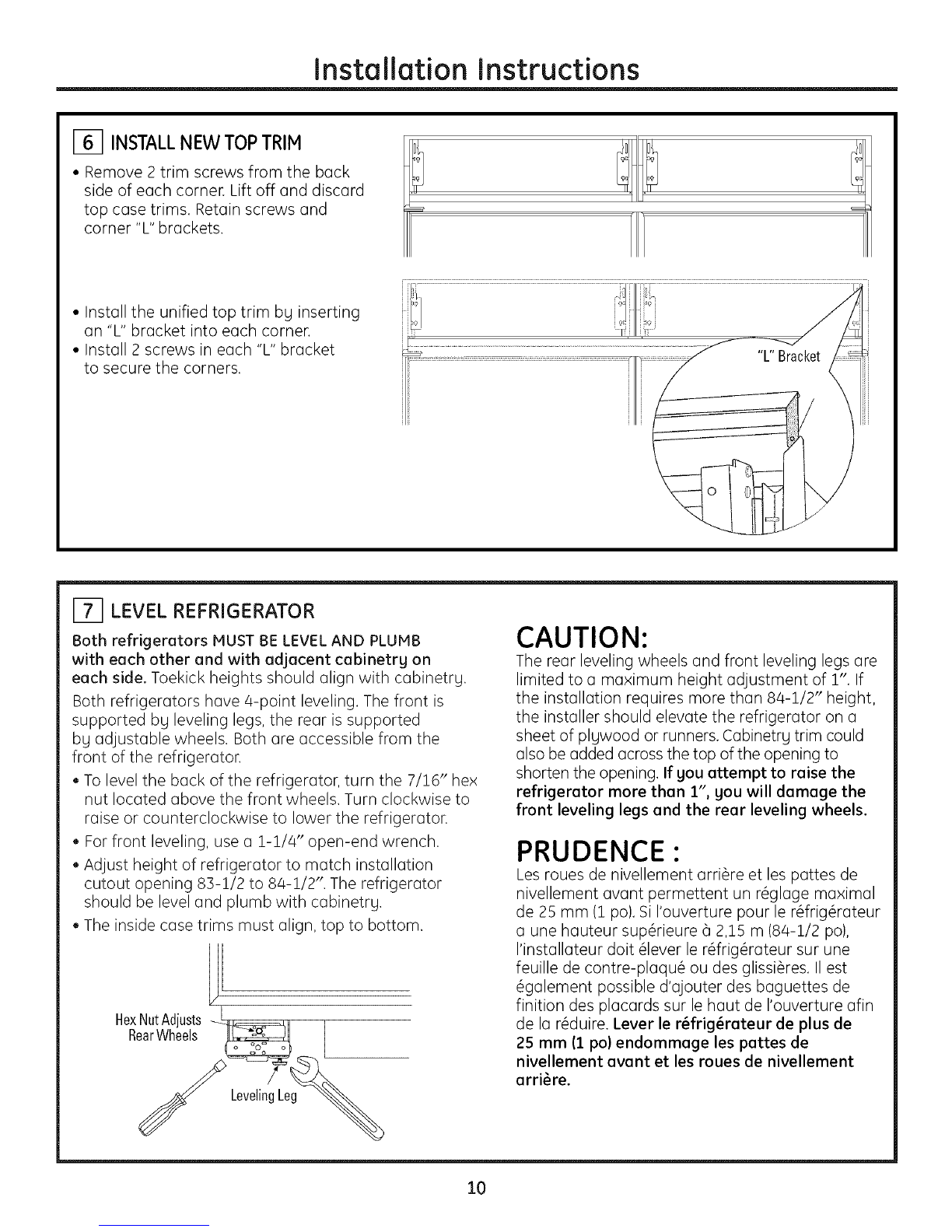
Step 6, Install New Top Trim ........!0
Step 7, Level Refrigerator ..............!0
Step 8, Alternate Anti-Tip
Procedure ..............................!!
Step 9, Secure Refrigerator
to Cabinetrg ........................ii
Step !0, Install Center
Trim Strip ............................12
Step !!, Install Grille BaseCover....!2
Step 12, Remove Both Grille
Panels (if present) ..........13
Step 13, Install Grille Panel
Onto Hinges ......................13
Step 14, Adjust Door Swing ..........14
Step 15, Check and Correct
Door Alignment ..............14
Step 16, Connect Water Supplg ..!6
Step 17, Connect Power ................17
Step 18, Start Icemaker ................17
Step 19, Install Toekick ..................17
2

Design Guide
THE INSTALLATION SPACE
The installation space must be 71-1/2",
f 71-1/2"FinishedWidth ........................................f
ll 2-5'16" ', "1 Wall
/k 5/'j E!ectricalf 24-3/ 6"-I View
--/ _ 6 , mm_ 6" |
!, 1 t
max I 10 i ]u .
83-I/2"tl ' 75 From
rain J_ 24"Cutout i Finished
FinishedI Depth , Floorto
• I ,, Bottomof
upenmg| _" W " 5" Electrical
I / "t aterSupply ,, WaterSupply T Area
" i I _ j
/ I, i
Z ............26 ...................\ /: ............26" .................\
3-1/2" 3-1/2"
Water And Electrical Locations
Electrical and water supply must be located
as shown.
The cutout depth must be 24"
The refrigerator will project forward, slightly
beyond adjacent cabinetry, depending on your
installation.
Cutout depth beneath a soffit:
When installed beneath a soffit, the soffit cannot
exceed the 24" installation depth shown. The top
case trim overlaps the bottom of the soffit.
Additional Specifications
cA separate 115 volt 60Hz., 15 or 20 amp power
supply is recommended for each product, An
individual properly grounded branch circuit or
circuit breaker is recommended. Install properly
grounded 3-prong electrical receptacles recessed
into the back wall, Electrical must be located on
rear wall as shown,
NOTE: GFI (ground fault interrupter)is not
recommended.
Both water lines can enter the opening through
the floor or back wall. Route GE SmartConnect"
kit or 1/4" O.D. copper tubing between the cold
water line and the water connection location.
The tubing should be long enough to extend to
the front of the refrigerator. Installation of an
easily accessible shut-off valve in the water
line is required.
DIMENSIONS AND CLEARANCES
71-1/2" 25-3/4"
CaseWidth CaseDepth
83-1/2"
atRear
28-11/16"
DepthIncluding
Handles
72"Frame
toFrame '
Width
Shippingheight.The
refrigeratorscanbe
adjustedtofit intoa
cutoutthatis83-1/2"
min.to84-1/2"max.
Notethatthetopcase
trimatthefrontis1/2"
higherandwilloverlap
uppercabinetryor
soffit.Uselevelinglegs
andwheelsfora
maximum1"height
adjustment.
Product Clearances
These refrigerators are equipped with a 2-position
door stop. The factory set 130 ° door swing can be
adjusted to 90 ° if clearance to adjacent cabinets
or walls is restricted.
25"_
Min.toi130° Door
WallI
/L
0 ,!
H 130° Door
Swing Swing
11
q-' '-F
iL
__25"__I
Min.to
Wall
/,,
,, "":::",,:::,,::::!
Allow 25" minimum clearance for a full 130° door
swing. Allow 15" for pan removal.
5" minimum clearance is required when door swing
is adjusted to 90°,If the 90° door stop position is
used, pan access is maintained, but pan removal
is restricted.
See illustrations on pages
4 and 5 to determine door
swing interaction with
adjacent cabinets or
countertops,
T
90° Door 123-7/8"
Swing / Behind
, !, _Frame
L! i
!i 36-3/4-
90o.........
5" Minimumto
Wall

Design Guide
Refrigerator 23-7/8"From
Rearof
Refrigerator
Case
Trim
_J 1/2"
1/4"
Frameless Cabinets: The case trim
overlaps cabinets at the top and sides.
Therefore, frameless cabinets mag require
filler strips to prevent interference with
cabinet door swing. The opening must
allow for filler strips.
1-1/4"
3/4" 1-3/4" 2-3/4"
1-1/2" 2-1/2"
2-1/4"
.
3/4" Overlay
Panel
",, (NominalSize)
Door
1-1/4"
Top View
130°DOOR SWING
(factorg setting)
Scale 1:1

Design Guide
- Frameless Cabinets- The
case trim overlaps cabinets
at the top and sides.
Refrigerator Therefore, frameless
J_ CaseTrim cabinets mag require
J .......... filler strips to prevent
I interference with cabinet
I door swing. The opening
t must allow for filler strips.
_°23-7/8"
\ -- ] FromRearof
i.... ',--- ',.... ,,-- 1/4
iq:i.....u
j i i i
_"_._ L
............. 1-1/4
I I ! ............. 1-1/2"
E_
I I ;;;;;;;;! ',
Jl ',
I I
II
I I !
I I
I I ::::} ',
I I
I I
II
Jl Door
I I I
I I I
II
I I
II 'I
II .......
LI i
, .
Ill , 3/4Overlay
I] Pane
i ! i
, , NominalSize
I I
i
Top V0ew II
• , ,
i i
@ i i
90 DOOR SWING II , .........
II I ', '
•
(opbonal setting) II , u
II I i "
scale 1:1 , 1-1/4"
II
5

Installation Instructions
TOOLS REQUIRED
• Tinsnips to cut banding
• Stepladder
• Bucket
• Level
• Appliance dollg
+ Tubing cutter
+ 7/16" open-end wrench
• #2 Phillips screwdriver
• Drill and appropriate bits
• 5/16",7/16" socket
Safetgglasses
1-1/4" and 1/2" open-ended wrench
• Pliers
,, !/4" ratchet or 1/4" angled wrench
HARDWARE SUPPLIED
• Water filter bgpass plug
• Anti-Tip brackets
,, 1/4"nut and ferrule
TRIM SUPPLIED
A. Soffit vent top
13. Left inside case trim
C. Right inside case trim
D. Center U-shape trim
E. Grille base wrap
F. Grille panel
G. Toekick
H. Foam spacer pads
I. Phillips screws
g. Package of 12 plastic spacers
MATERIALS REQUIRED
,, 71" long 2x4 for Anti-Tip support
• 1/4" copper water line tubing or two GE
SmartConnect +' Refrigerator Tubing kits
• Two water shut-off valves
• Screws to secure refrigerator to cabinetrg
• Stick-on hook and loop fastener strips for 1/4"
side panels
FLOORING
For proper installation, this refrigerator must be
placed on a level surface of hard material that is at
the same height as the rest of the flooring. This
surface should be strong enough to support a fullg
loaded refrigerator, or approximatelg 2,400 Ibs.
NOTE: Protect the finish of the flooring. Cut a large
section of the cardboard carton and place under the
refrigerator where gou are working.
A
D C
G F E <_'-
GROUNDING THE REFRIGERATOR
IMPORTANT--(Please read carefullyl
FOR PERSONAL SAFETY,THIS APPLIANCE MUST BE
PROPERLYGROUNDED.
The power cord of this appliance is equipped with
a 3-prong (grounding) plug which mates with a
standard three-prong (grounding) wall receptacle
to minimize the possibilitg of electric shock hazard
from this appliance.
Have the wall outlet and circuit checked bg a
qualified electrician to make sure the outlet is
properlg grounded.
Where a standard 2-prong wall outlet is encountered,
it is gour personal responsibilitg and obligation to
have it replaced with a properlg grounded 3-prong
wall outlet.
DO NOT, UNDER ANY
CIRCUMSTANCES, CUT
OR REMOVE THE THIRD
(GROUND) PRONG FROM
THE POWER CORD.
DO NOT USEAN ADAPTER PLUGTO CONNECT THE
REFRIGERATORTO A 2-PRONG OUTLET.
DO NOT USEAN EXTENSION CORD WITH THIS
APPLIANCE.

Installation Instructions
I_1 REMOVEPACKAGING
CAUTION:Refrigeratorismuch heavierat the top than at
the bottom-be careful when moving.When usinga hand truck,
handle from sideonly.
PRUDENCE:Lerdrig@ateurestbeaucoupplusIourd
enhautqu'enbas.IIfaut@treprudentIorsdesd@lacements.
Siundianeestutilis@,ilfaut souleverlerdrig@rateursurlec6t@
seulement.
• Carefullycut banding at the top and bottom, remove outer
carton.
• Slideout back corner posts(2).
• Slidecarton off top of cabinet.
NOTE:ITISNOTNECESSARYTOLAYCABINETDOWNINORDER
TOREMOVESKID!
• Theunit is securedto the skidwith 4 slotted tie-down straps.
Removethe four 5/16" bolts from the basechannels in the
tie-downs.
Remove
Fie-Downs
./
• Removethe four 7/16"
bolts securingthe straps
to the skid
CAUTION:DONOT
ATTEMPTTOROLLUNIT
OFFSKID.
PRUDENCE:
ILNEFAUTPASESSAYER
DEFAIREROULERLE
REFRIGERATEURPOUR
L'ENLEVERDELAYPALETTE.
• Support blockson the bottom of the refrigeration case must
be removed beforethe refrigerator istaken offthe skid or
damage will occur,Carefullytilt refrigerator and slideblocks
out from beneath.
• Liftthe refrigerator off the skidwith an appliance dolly.
Handlefrom the sides.
_1 INSTALL WATER LINES
• A cold water supply isrequired for automatic icemaker
operation.Thewaterpressuremustbebetween40and120
p.s.i.
• Route1/4" ODcopper or GESmartConnecf" plastictubing
between housecold water line and the water connection
location.
• Tubing shouldbe long enough to extend to the front of the
refrigerator.Allow enough tubing to accommodate bend
leading into the water lineconnection.
NOTE:The only GEapproved plastictubing issuppliedin
the GESmartConnecf" RefrigeratorTubingkits.Do not use
any other plasticwater supply line because the line isunder
pressureat alltimes. Othertypes of plasticmay crack or
rupture with age and cause water damage to your home.
GESmartConnecf" RefrigeratorTubing Kitsare available in the
following lengths:
2'(,6m) WXO8XIO002
6'(1,8 m) WXO8XIO006
15' (4%m) WXO8X10015
25' (7.6m) WXO8X10025
Shut off the main water supply.
Turnon the nearestfaucet long enough to clearthe lineof
water.
• Installa shut-off valve between the icemakerwater valve and
cold water pipe in a basement or cabinet. Theshut-off valve
should be located where it will be easily accessible.
_jiji1[iiiij[iiiij[iiiij[iiiij[iiiij[iiiij[iiiij[iiiij[iiiij[iii[iiiii11[iiiii{_i
\ Waterline J'
Tubing
• Turn on the main water supply and flush debris.
Runabout a quart of water through the tubing into
a bucket. Shutoff water supply at the shut-off valve.
NOTE:Saddletype shut-off valvesare includedin many water
supply kits.Beforepurchasing,make surea saddletype valve
complies with your local plumbing codes.
NOTE:Commonwealth of Massachusetts PlumbingCodes
248CNRshallbe adhered to. Saddlevalvesare illegal and use
is not permitted in Massachusetts.Consultwith your licensed
lumber.
Ifthe water supply to the refrigerator isfrom a Reverse
OsmosisWater System,usethe refrigerator's filter bypassplug.
Usingthe refrigerator's water filtration cartridge with the RO
filter can result in hollow ice cubes.
erBypass:

Installation Instructions
J3] INSTALL NEW SIDE TRIM
CAUTION: Handle parts with care to avoid
scratching.
• Remove the inside case trim on both refrigerators.
FoamSpacer
Pads
/
/
/
/Remove the Phillips head screws from the inside
case trim of each product as shown. Remove and
discard side trim. Retain screws.
Applg the supplied foam spacer pads to the mating
side of one product as shown.
Install new side case trim with notches toward the
bottom. Install with original screws.
J_ INSTALL SIDE PANELS
Side panels must be used whenever the sides
of the refrigerator will be exposed. The i/4"
side panels will slip into the side case trim.
Secure the panels to the refrigerator with
stick-on hook and loop fastener strips. Order
the side panels from the cabinet manufacturer.
Cut a notch in the top front corner as shown
to allow clearance for corner kegs in the front
side trim.
Skip this step if gou are not using side panels.
* Dependingon
installationheight

Installation Instructions
151 INSTALL ANTI-TIP BRACKETS
WARNING: A.TI-TIPPRECAUTIO.S
The refrigerator is top-heavg and must be secured
to prevent the possibilitg of tipping forward.
ATTENTION : PRECAUTIONSCONTRELES
BASCULEMENTS
Le r6frig6rateur est beaucoup plus Iourd en
haut et il faut le maintenir en place pour 6viter
la possibilit6 de son basculement vers I'avant.
• Cut a 2" x 4" x 71" block and secure the block
to the mounting brackets provided using #12
or #1/4 wood screws.
2x4Cut _,
71"Length
InstallationHeight Mounting
FromFloor Bracket
Screws Mountedinto j
VerticalWallStuds
• Secure the bracket with wood block to the back
wall so that it is 84" (or gour installation height)
from the finished floor. Use #12 or #1/4 wood
screws. See illustration.
Brackets
Required
B
SideView
Soffi[ Brackets
-- Not Required
-- Beneatha
Soffit
-I
[5] INSTALL ANTI-TIP BRACKETS (cont.)
• Screws must penetrate at least one inch into
vertical wall studs.
• Before pushing the refrigerator into the opening,
plug the power cord into the receptacle. Open the
grille panel and reach into the opening at the
back to grasp the power cord. Pull the power cord
into the opening as gou push the refrigerator back.
• Gentlg push refrigerator into the opening with
hands against front corners.
IMPORTANT NOTE: When the refrigerator is
installed under a soffit or if there is not enough
height for this method of security, brackets cannot
be used. Proceed to step 6 to level the refrigerator
and then to step 8 to secure refrigerator to
cabinets. The refrigerator must be secured
to prevent tipping.

Installation Instructions
[_ INSTALLNEW TOPTRIM
• Remove 2 trim screws from the back
side of each corner. Lift off and discard
top case trims. Retain screws and
corner "L" brackets.
•Install the unified top trim by inserting
an "L" bracket into each corner.
• Install 2 screws in each "L" bracket
to secure the corners. "L"Bracket
[_ LEVEL REFRIGERATOR
Both refrigerators MUST BE LEVEL AND PLUMB
with each other and with adjacent cabinetrg on
each side. Toekick heights should align with cabinetrg.
Both refrigerators have 4-point leveling. The front is
supported bg leveling legs, the rear is supported
bg adjustable wheels. Both are accessible from the
front of the refrigerator.
• To level the back of the refrigerator, turn the 7/26" hex
nut located above the front wheels. Turn clockwise to
raise or counterclockwise to lower the refrigerator.
• For front leveling, use a 2-2/4" open-end wrench.
• Adjust height of refrigerator to match installation
cutout opening 83-!/2 to 84-2/2". The refrigerator
should be level and plumb with cabinetrg.
• The inside case trims must align, top to bottom.
HexNutAdjusts _ll L
RearWheels _ [
LevelingLe
CAUTION:
The rear leveling wheels and front leveling legs are
limited to a maximum height adjustment of 1". If
the installation requires more than 84-1/2" height,
the installer should elevate the refrigerator on a
sheet of plgwood or runners. Cabinetry trim could
also be added across the top of the opening to
shorten the opening. If you attempt to raise the
refrigerator more than 1", gou will damage the
front leveling legs and the rear leveling wheels.
PRUDENCE:
Les roues de nivellement arri@e et les pattes de
nivellement avant permettent un r_glage maximal
de 25 mm (1 po). Si I'ouverture pour le r_frig@ateur
a une hauteur sup@ieure _ 2,15 m (84-1/2 po),
I'installateur dolt _lever le r_frig@ateur sur une
feuille de contre-plaqu_ ou des glissi@es. II est
_galement possible d'ajouter des baguettes de
finition des placards sur le haut de I'ouverture afin
de la r_duire. Lever le r_frig_rateur de plus de
25 mm (1 po) endommage les pattes de
nivellement avant et les roues de nivellement
arri_re.
10

Installation Instructions
_1 ALTERNATE ANTI-TIP PROCEDURE
The refrigerator must be secured to prevent tipping.
The anti-tip brackets cannot be used on metal
wall studs. Use this Alternate Procedure to secure
the refrigerator against tip-over whenever metal wall
studs are encountered and there is no soffit.
• Raise the grille panel to access case trim.
• Usea 3/16" bit to drill four evenly spaced clearance
holes through the metal top case trim.
• Use a 1/16" bit to drill pilot holes through the metal
clearance holes and into the wood soffit. The holes
should be centered in the soffit or a 3/4" min. wood
brace. The brace spanning the enclosure must be
securely fastened to cabinets on both sides.
• Install four 1-1/2" drywall screws into the pilot holes.
TopCaseTrim
InstallFour1-1/2"DrywallScrews
ThroughTrimandIntoSoffitor
3/4"Min.WoodBrace
SideView
TopCaseTrim
19] SECUREREFRIGERATORTO CABINETRY
Whenever possible, perform this step for anti-tip II
security, or when anti-tip brackets cannot be used.
The refrigerator must be secured to prevent tipping.
• Raise the grille panel to access case trim.
• Drill hole in trim and drive screw through the trim -_
into adjacent cabinet. ,I
• Follow the same procedure on the opposite side. DriveScrewsThrough
CaseTrimandInto
AdjacentCabinets
11

Installation Instructions
E_ INSTALLCENTERTRIMSTRIP
• Open doors fully.
• Starting at the top, press center trim strip over the
inside case trims of both refrigerators.
• Continue pressing trim until you reach the bottom of
the case trims. The trim should align with the top and
bottom of case trims.
CaseTrim
U-Shape
Trim
[] INSTALLGRILLEBASECOVER
•Open doors fully.
• Grasp grille panel at the center and lift up to stop position.
• Remove one screw on each end of the grille base wrap.
Remove the wrap.
• Install the unified double width grille base wrap by
slipping the notched ends over the hinges.
• Install one screw on each end and 2 at the center.
_ Remove _0
Screws
UnifiedBaseWrap PlaceTrim
OverHinges
12

Installation Instructions
[_] REMOVEBOTHGRILLEPANELS(if present)
• Remove 3 screws holding the grille panel to the
hinge on each side. Lift grille panel off the hinges.
Discard both grille panels. Retain screws.
Leave hinges in open position.
Do not push hinges back.
GrillePanel
Remove3 Screws
[_ INSTALLGRILLEPANELONTO HINGES
• Place the new unified grille panel over the hinges,
matching screw hole locations.
• Install 3 screws through each hinge and
into the bracket.
• Grasp panel at the center and pull down to close.
NOTE: Check alignment of grille panel to the top of
the doors. To adjust, loosen bracket hinge screws
on all/4 hinges. Adjust and tighten screws. Install3Screws
GrillePanel
13

Installation Instructions
[_ ADJUSTDOORSWING
NOTE: This refrigerator has a 2-position door stop.
When space does not allow the door to swing open
fullg to !]0 °, gou mag change the door swing to
a 90 ° opening. Skip this step if door opening is
satisfactory for your installation situation.
L
GrilleBaseWrap I_
• Lift the grille panel to access the wire cover trim.
• Remove screws on both sides of the wire cover
trim and lift off.
• Use pliers to unscrew door stop and reinstall into
the 90 ° position. PinLocation
asShipped
For130°
DoorSwing
[_ CHECKAND CORRECTDOORALIGNMENT
• Close the grille panel and both doors.
• Check to be sure the unit is level.
See Step 7 to level the unit.
• Check that the freezer drawers and bottom of doors
are horizontal and even at the lower inside corners.
• Carefully measure the inside corners to determine
if an adjustment is needed. A difference of 1/32" is
acceptable and does not require adjustment.
SKIP THIS STEP IF DOORS ARE LEVEL.
IMPORTANT: If the doors are not evenlg aligned,
theg must be removed and spacers must be installed
to raise or lower one or both doors.
Spacer
Location
\II
Spacer
Location
/
14

[] CHECKAND CORRECTDOORALIGNMENT(cont.)
DETERMINE CORRECT SPACER
Thiskit contains 12 plasticspacers(2of each size).Match
spacerto illustration belowto besure gou have selected
the correct sizeas determined in the charts below.
L 3/32" _ 1/8"
L 5/32" L 3/16"
1/4" L 9/32"
RH Fresh Food door is higher then the LH door:
'[J_ _ Dimension
A
Select and install the correct spacer on one or both
Fresh Food hinges as determined bg Dimension A.
RH Door Install Install
Dim. A LH Spacer RH Spacer
1/32" to 1/16" 1/4" no chanqe
1/16" to 3/32" 1/4" 3/16"
s/s2" to !/8" !/4" s/s2"
!/8" to 5/32" !/4" !/8"
5/32" to 3/16" 9/32" 1/8"
3/16" to 7/32" 9/32" 3/32"
LH Fresh Food door is higher then the RH door:
Dimension
A
Select and install the correct spacer on one or both
Fresh Food hinges as determined bg Dimension A.
LH Door Install Install
Dim. A LH Spacer RH Spacer
1/32" to 1/16" no change 1/4"
1/16" to 3/32" 3/16" 1/4"
3/32" to 1/8" 5/32" 1/4"
1/8" to 5/32" 1/8" 1/4"
5/32" to 3/16" 1/8" 9/32"
3/16" to 7/32" 3/32" 9/32"
15

Installation Instructions
I_1 CHECKAND CORRECTDOORALIGNMENT(cont.)
Remove
3Screws
1. Open the grille panel. Removethe grille base wrap.
2. Remove ] screws on the hinge plate.
3. Use pliers to remove door stop pin.
Liftoffandreplace
plasticspacer
4. Lift door off bottom hinge pin. Place the door on a
protected surface; be careful not to damage the door.
5. Remove the original plastic spacer.
6. Place the selected spacer over the hinge.
7. Reverse all steps to replace the door.
[] CONNECTWATERSUPPLY
Connect both refrigerators to the water supplg. _
• Locate and bring tubing to the front of the cabinet.
Turn the water on to flush debris from line. Run
about a quartofwater through tubingintoa
bucket,then shutoffwater.
Copper Tubing:
Slip a !/4" nut and ferrule (provided) over both
ends of the copper tubing. Insert tube into the
union fitting on the unit and tighten nut to union.
Turn on the water to check for leaks.
GE SmartConnect T"Tubing:
Insert the molded end of the tubing into the
refrigerator connection. Tighten the compression
nut until it isjust hand tight.
• Tighten one additional turn with a wrench.
Overtightening can cause leaks!
Turn on the water to check for leaks.
NOTE: Hake sure excess tubing length does not
interfere with drawer closing or toekick installation.
16

Installation Instructions
[] CONNECTPOWER
• Check to be sure the power cord is plugged
into the receptacle.
r_
I_ Raise
6rille
Panel
Electrical MasterLight
Outlet Switch
• Check to make sure power to refrigerator is on
bg opening refrigerator door to see if interior
lights are on.
• The temperature controls are preset at ]7°F
for the fresh food section and 0°F for the freezer.
• Allow 2/4hours for temperature to stabilize
before making adjustments.
1_ INSTALLTOEKICK
• Install the toekick with 4 screws provided,
one on each side and 2 in the center.
"%
IMPORTANT: The toekick must be positioned with
the vented slots on the top side. The vented toekick
must remain unobstructed for proper air circulation
and refrigerator operation.
[] STARTICEMAKER
• Flip the switch to I (ON}. The icemaker will begin
operation automaticallg.
• Be sure nothing interferes with the sweep of the
feeler arm.
• Discard the first full bucket of ice cubes.
• To turn the icemaker off, set the switch to O IOFF}.
17

Notes
18

Notes
19

49-60469-1
22401234PO01
11-o6 JR
Printed in the United States
NOTE: While performing installations described in this book,
safetg glasses or goggles should be worn.
®
For Honogram Iocalservicein gourarea, call
1.800.444.1845.
NOTE: Product improvement is a continuing endeavor
at General Electric. Therefore, materials, appearance
and specifications are subject to change without notice.
Monogram:
GEConsumer& hldustrial
GEAppliances
General Electric Company
Louisville, KY40225
ge com
@2006GECompany
Other manuals for Monogram ZICP720
2
Table of contents
Other GE Refrigerator manuals

GE
GE Profile PSH25MGW User manual

GE
GE Monogram ZIDI240WII User manual

GE
GE GE Profile Energy Star PSS23LSS Manual

GE
GE GTH18CCEHRWW Operating instructions

GE
GE TBF21RW User manual

GE
GE Profile PSCF3RGX User manual

GE
GE GSH25JFPACC and Operating instructions

GE
GE PFSS9PKYSS - 28.5 CF Ref Assembly instructions

GE
GE ESHF5MGXGEWW Safety guide

GE
GE GSH22JGC Manual