GE PSH23PGR Series How to use

– 2
!
IMPORTANT SAFETY NOTICE
The information in this service guide is intended for use by
individuals possessing adequate backgrounds of electrical,
electronic, and mechanical experience. Any attempt to repair a
major appliance may result in personal injury and property
damage. The manufacturer or seller cannot be responsible for the
interpretation of this information, nor can it assume any liability in
connection with its use.
WARNING
To avoid personal injury, disconnect power before servicing
this product. If electrical power is required for diagnosis or test
purposes, disconnect the power immediately after performing the
necessary checks.
RECONNECT ALL GROUNDING DEVICES
If grounding wires, screws, straps, clips, nuts, or washers used to
complete a path to ground are removed for service, they must be
returned to their original position and properly fastened.
GE Consumer & Industrial
Technical Service Guide
Copyright © 2004
All rights reserved. This service guide may not be reproduced in whole or in part
in any form without written permission from the General Electric Company.

– 3 –
3-Way Valve .....................................................................................................................27
Accumulator .....................................................................................................................40
Check Valve .....................................................................................................................40
Components.....................................................................................................................18
Components Locator Views .............................................................................................11
Condenser Fan ................................................................................................................21
Control Board Connector Locator ....................................................................................12
Control Features ..............................................................................................................7
Defrost Cycles..................................................................................................................22
Dispenser Light ................................................................................................................10
Dispenser Lock ................................................................................................................10
Dispensing Functions.......................................................................................................10
Evacuation and Charging Procedure ...............................................................................17
Freezer Evaporator ..........................................................................................................31
Freezer Evaporator Fan...................................................................................................20
Freezer Section Cooling ..................................................................................................15
Fresh Food and Freezer Section Cooling ........................................................................16
Fresh Food Evaporator ....................................................................................................37
Fresh Food Evaporator Fan.............................................................................................19
Fresh Food Section Cooling ............................................................................................14
Illustrated Parts ................................................................................................................44
Introduction ......................................................................................................................4
Inverter.............................................................................................................................24
Inverter Compressor ........................................................................................................26
Liner Protection Mode......................................................................................................10
Nomenclature...................................................................................................................6
Refrigeration System .......................................................................................................14
Replacing Freezer Evaporator Using the Brazing Method...............................................33
Replacing Freezer Evaporator Using the LOKRING Method ............................................35
Replacing Fresh Food Evaporator Using the Brazing Method.........................................38
Replacing Fresh Food Evaporator Using the LOKRING Method ......................................39
Replacing the 3-Way Valve ..............................................................................................29
Schematic ........................................................................................................................43
Technical Data .................................................................................................................5
Thermistors ......................................................................................................................18
Troubleshooting ...............................................................................................................41
Warranty...........................................................................................................................62
Table of Contents

– 4
This new Arctica dual evaporator refrigerator has the following features:
• Separate freezer and fresh food evaporators with independent cooling.
• No damper/air inlet assembly in the fresh food section creates more usuable space on the top shelf.
• Greater fresh food humidity to keep food
fresher, longer.
• 20% less freezer defrost for better food
preservation.
• 3-Way valve to direct refrigerant flow.
• Nearly silent, only 30 dBA.
The 3-speed compressor is controlled by
an inverter that receives input from the
low voltage DC side of the main control
board. The inverter always has 120 VAC
applied when the refrigerator is connected
to power. The main control board still makes
compressor decisions based on the input of
thermistors, door-open time, and input from
the temperature control panel. The main
control board also operates the condenser
fan, fresh food fan, freezer fan and adaptive
defrost.
The most significant difference from previous
models is that the freezer and fresh food
evaporators are separate. The 3-way valve
directs refrigerant flow to each evaporator as needed. The fresh food section no longer relies on the
freezer evaporator for cooling. The evaporators are controlled separately by the main control board
through the 3-way valve.
Introduction

– 5 –
Technical Data
DIS
C
ONN
E
C
T
P
OW
E
R
C
O
R
D
B
E
F
O
R
E
S
E
R
VI
C
ING
IM
P
O
R
TANT -
R
E
C
ONN
E
C
T A
LL
G
R
OUNDING D
E
VI
C
E
S
All parts of this appliance capable of conducting
electrical current are grounded. If grounding wires,
screws, straps, clips, nuts or washers used to
complete a path to ground are removed for service,
they must be returned to their original position and
properly fastened.
E
L
E
C
T
R
I
C
A
L
S
PE
C
I
F
I
C
ATIONS
Temperature Control (Position 5) ......................... 7-(-11 ) F
Defrost Control .......................................... 60hrs @ 45 min
w/ no door openings
Overtemperature Thermostat .............................. 140-110 F
Defrost Thermistor ........................................................ 75 F
Electrical Rating: 115V AC 60 Hz ......................... 11.6 Amp
Maximum Current Leakage ................................... 0.75 mA
Maximum Ground Path Resistance .................. 0.14 Ohms
NO
L
OAD
PE
R
F
O
R
MAN
C
E
Control Position MID/MID
and Ambient of: ...............................................70 F90 F
Fresh Food, F ................................................ 34-40 34-40
Frozen Food, F .............................................. (-3) 3 (-3) 3
Run Time, % ...................................................... <80 80-100
R
E
F
R
IG
E
R
ATION SYST
E
M
Refrigerant Charge (R134a) ............................... 6.5 ounces
Compressor ....................................................833 BTU/hr @
3000 RPM
Minimum Compressor Capacity ......................... 22 inches
Minimum Equalized Pressure
@ 70 F ....................................................................... 40 PSIG
@ 90 F ....................................................................... 54 PSIG
IM
P
O
R
TANT SA
F
E
TY NOTI
C
E
This information is intended for use by individuals
possessing adequate backgrounds of electrical,
electronic and mechanical experience. Any attempt
to repair a major appliance may result in personal
injury and property damage. The manufacturer or
seller cannot be responsible for the interpretation of
this information, nor can it assume any liability in
connection with its use.
INSTA
LL
ATION
Minimum clearance required for air circulation:
TOP ............................................................................................. 1"
SIDES ................................................................................... 0.125"
REAR ........................................................................................ 0.5"
AI
R
FL
OW
E
VA
P
O
R
ATO
R

– 6
Nomenclature
The nomenclature plate is located on the
upper right wall of the fresh food compartment.
It contains the following information:
The letter designating
the year repeats every
12 years.
Example:
T - 1974
T - 1986
T - 1998
Serial Number
The first two numbers of the serial number
identify the month and year of manufacture.
Example: AG123456S = January, 2004
A- JAN 2005 - H
D - FEB 2004 - G
F - MAR 2003 - F
G - APR 2002 - D
H - MAY 2001 - A
L - JUN 2000 - Z
M - JUL 1999 - V
R - AUG 1998 - T
S - SEP 1997 - S
T - OCT 1996 - R
V - NOV 1995 - M
Z - DEC 1994 - L
P S H 23 P G R A F BB
Door Type
F - Flat
R - Right
L - Left Door Swing
Exterior Color
WW - White on White
BB - Black on Black
CC - Bisque on Bisque
SV - Stainless Visor
Engineering
A - Initial Design
B - 1st Revision
Model Year
R - 2004
Icemaker/Exterior
B - Non Dispenser
IM Ready
D - Cubed Ice/Water
E - Cubed/Crushed/
Water
F - 6-Month Filter
Cubed/Crushed
G - 1-Year Filter
Cubed/Crushed
I - In-line Filter/Indicator
Cubed/Crushed
Water
S - Stainless steel
Dispenser Trim
Brand/Product
G - GE
H - Hotpoint
P - Profile
E - Eterna
S - GE Select
Configuration
S - Side by Side
T - Top Mount
Depth/Power
H - Inverter Compressor
S - Standard Depth
T - Tropical
G - Global
Capacity
(cubic feet) AHAM Rated Volume
Interior Features/Shelves
A - Leader Wire
D - Deluxe Wire
F - 6 Month Filter
I - Deluxe Glass
K - Spillproof/Slideout Glass
P - Dual Evaporator
S - Stainless Steel Doors
Q - Showcase Derivative
U - AVB Derivative
W - HPS Derivative
X - Regional Derivative
Mini-Manual Location
• Model and Serial
Number
• Minimum
Installation
Clearances
• Electrical Voltage,
Frequency
• Maximum
Amperage Rating
• Refrigerant Charge
and Type
Nomenclature

– 7 –
• To change the temperature, press and release the WARMER or COLDER pad. The SET light will
come on and the display will show the set temperature.
• To change the temperature, tap either the WARMER or COLDER pad until the desired temperature
is displayed.
• Refrigerator temperatures can be adjusted between 34°F and 44°F and the freezer temperatures
can be adjusted between –6°F and +6°F.
• Once the desired temperature has been set, the temperature display will return to the actual
refrigerator and freezer temperatures after 5 seconds. Several adjustments may be required. Each
time you adjust controls, allow 24 hours for the refrigerator to reach the temperature you have set.
• To turn the cooling system off, tap the WARMER pad for either the refrigerator or the freezer until
the display shows OFF. To turn the unit back on, press the COLDER pad for either the refrigerator
or freezer. The SET light will illuminate on the side you selected. Then press the COLDER pad
again (on the side where the SET light is illuminated) and it will go to the preset points of 0°F for the
freezer and 37°F for the refrigerator.
• Setting either or both controls to OFF stops cooling in both the freezer and refrigerator
compartments, but does not shut off electrical power to the refrigerator.
Control Features
• The temperature controls are preset in the factory at 37°F
for the refrigerator compartment and 0°F for the freezer
compartment.
• Allow 24 hours for the temperature to stabilize to the preset
recommended settings.
• The temperature controls can display both the SET
temperature as well as the actual temperature in the
refrigerator and freezer.
• The actual temperature may vary slightly from the SET
temperature based on usage and operating environment.
• Setting either or both controls to OFF stops cooling in both
the freezer and refrigerator compartments, but does not shut
off electrical power to the refrigerator.

– 8
Empty the pan. Place the Chill/Thaw
tray in the pan. Place the items on the
tray and close the pan completely.
Select the ExpressThaw,
™
ExpressChill
™
or SelectTemp
™
pad. The display and
SET light will come on. Tap the pad
until the light appears next to the
desired setting. Use the chart to
determine the best setting to use.
■To stop a feature before it is
finished, tap that feature’s pad
until no options are selected and
the display is off.
■During ExpressThaw
™
and
ExpressChill,
™
the display on the
controls will count down the time
in the cycle.
■After the ExpressThaw
™
cycle is
complete, the pan will reset to the
MEAT setting (31°F) to help preserve
thawed items until they are used.
■The displayed actual temperature of
the CustomCool pan may vary slightly
from the SET temperature based on
usage and operating environment.
NOTE: For food safety reasons, it is
recommended that foods be wrapped
in plastic wrap when using ExpressThaw.
™
This will help contain meat juices and
improve thawing performance.
About CustomCool™
.
The CustomCool
™
feature is a system of
dampers, a fan, a temperature thermistor
and a heater. Depending on the function
selected, a combination of these will be
used to quickly chill items, thaw items or
hold the pan at a specific temperature.
The pan is tightly sealed to prevent the pan’s
temperature from causing temperature
fluctuations in the rest of the refrigerator.
The controls for this pan are located at the
top of the refrigerator with the temperature
controls.
How to Use
How it Works
ExpressThaw
™
ExpressChill
™

– 9 –
About TurboCool.™
How it Works
TurboCool rapidly cools the refrigerator
compartment in order to more quickly
cool foods. Use TurboCool when adding a
large amount of food to the refrigerator
compartment, putting away foods after they
have been sitting out at room temperature
or when putting away warm leftovers. It can
also be used if the refrigerator has been
without power for an extended period.
Once activated, the compressor will turn on
immediately and the fans will cycle on and
off at high speed as needed for eight hours.
The compressor will continue to run until
the refrigerator compartment cools to
approximately 34°F (1°C), then it will cycle
on and off to maintain this setting. After 8
hours, or if TurboCool is pressed again, the
refrigerator compartment will return to
the original setting.
How to Use
Press TurboCool. The refrigerator
temperature display will show TC.
After TurboCool is complete, the
refrigerator compartment will return
to the original setting.
NOTES: The refrigerator temperature
cannot be changed during
TurboCool.
The freezer temperature is not
affected during TurboCool.
When opening the refrigerator
door during TurboCool, the fans
will continue to run if they have
cycled on.
About the ice and water dispenser. (on some models)
To Use the Dispenser
Select CUBED ICE , CRUSHED ICE
or WATER .
Press the glass gently against the top of
the dispenser cradle.
The spill shelf is not self-draining.
To reduce water spotting, the shelf and
its grille should be cleaned regularly.
If no water is dispensed when the refrigerator is
first installed, there may be air in the water line
system. Press the dispenser arm for at least two
minutes to remove trapped air from the water
line and to fill the water system. To flush out
impurities in the water line, throw away the first
six glassfuls of water.
CAUTION: Never put fingers or any other
objects into the ice crusher discharge opening.
Locking the Dispenser
Press the LOCK CONTROL
pad for 3 seconds to
lock the dispenser and
control panel. To
unlock, press and
hold the pad again
for 3 seconds.
Dispenser Light
This pad turns the night
light in the dispenser
on and off. The light
also comes on when
the dispenser cradle is
pressed. If this light
burns out, it should be
replaced with a 6 watt
12V maximum bulb.
Quick Ice
When you need ice
in a hurry, press this
pad to speed up ice
production. This will
increase ice production
for the following
48 hours or until you
press the pad again.
Door Alarm
To set the alarm, press
this pad until the
indicator light comes
on. This alarm will
sound if either door is
open for more than
3 minutes. The light
goes out and the
beeping stops when
you close the door.
Spill Shelf

– 10
Liner Protection Mode
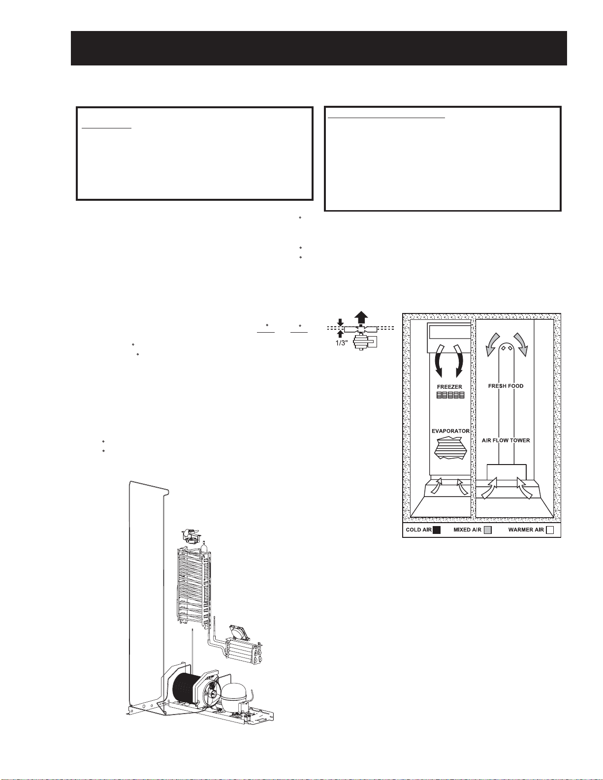
The dual evaporator model has separate liner
protection modes for each section. The specific
evaporator fan (freezer or fresh food) will start
and run on high speed if the door has been open
for 3 minutes.
This mode is controlled by 2 timers. Timer #1
monitors door-open time. A 3-minute door-open
count begins when the door is opened. If 3
minutes elapse before the door is closed, the liner
protection mode will become active. Once the
door is closed, timer #1 resets and liner protection
mode goes into standby. In standby, normal
fan operation resumes and timer #2 begins a
3-minute door-closed count. If 3 minutes elapse
without a door opening, liner protection mode will
completely deactivate. If a door is opened within
the timer #2 door-closed count, the remaining
time in the door-closed count will be deducted
from the timer #1 door-open count.
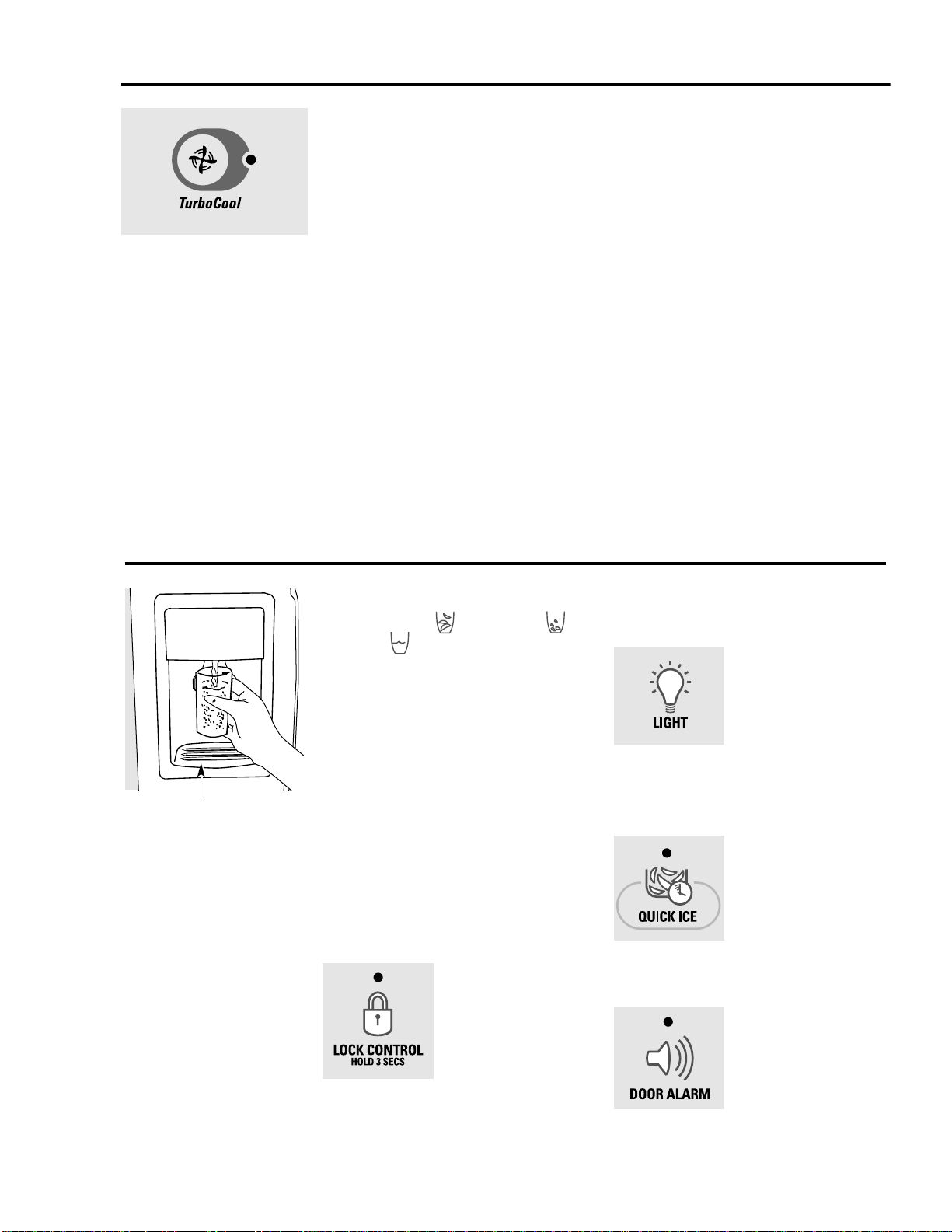
Dispenser Light
The LIGHT pad turns the dispenser light on and
off. When the light is turned off, it will fade out.
The dispenser light will come on automatically
when the dispenser cradle is depressed and will
fade out 5 seconds after it is released. The LIGHT
pad will not turn off the light during dispensing.
Dispensing Functions
The water, crushed ice, and cubed ice functions
are controlled by the main control board. To
select a function, press the appropriate pad on
the dispenser. The LED will light to identify the
selection.
To dispense ice cubes or crushed ice, choose
the appropriate pad and depress the dispenser
cradle. The solenoid and linkage assembly will
open the ice chute duct door to dispense the
ice. If cubed ice is selected, a solenoid located
behind the ice bucket will lift a rod along the side
of the bucket. This rod pulls a flapper away from
the cutter blades, allowing cubes to bypass the
ice crusher. The dispenser duct door will remain
open for 3 seconds after dispensing to allow all
ice to clear the chute.
The dispenser light will come on automatically
when the dispenser cradle is depressed and will
fade out 5 seconds after it is released.
To lock or unlock communication between the
dispenser and main control board, press the
LOCK pad and hold it for 3 seconds. The LOCK
LED will flash while the LOCK pad is pressed.
When the communication is locked, the LOCK
LED will be illuminated.
The status of other functions selected prior to the
initiation of the lock feature will be displayed. If
the lock is engaged while a mode is active, the
LED will remain on until that mode times out.
If the lock is engaged when the filter timer
expires, the LED will come on but cannot be reset
until the lock is turned off.
The lock feature will be restored in the event of a
power disruption.
Dispenser Lock
When the dispenser system is locked, no
dispenser command will be accepted. This
includes the dispenser cradle and will prevent
accidental dispensing that may be caused
by children or pets. If a pad or the cradle is
depressed with the system locked, it will be
acknowledged with three pulses of the LOCK
LED accompanied by an audible tone.

– 11 –
Components Locator Views
Rear View
Inverter
Main Control Board
Jumper Tube
Condenser
Water Valve
3-Way Valve
Front View
Freezer Evaporator
Fresh Food Evaporator
Accumulator
Evaporator Thermistor
Check Valve
Over Temp Thermostat
Note: The
check valve and
accumulator are
part of the freezer
evaporator and
are not available
separately.
Drier

– 12
Control Board Connector Locator
J1 or J10 - Earth (Ground)
J2 or J13 - Earth (Ground)
J5 - Custom Cool
J7 - Neutral, Door Switches, Custom Cool
Heater, Water Valve, Crusher Solenoid,
Auger Motor
J9 - Defrost Heater
J3 or J10 - 3-Way Valve
J11 - Line (L1)
J7
J2 or J13
J5
J4 or J16
K2
K1
K3
K4
K5
J15
J11
J9
Main Control Board
J2 or J13 - Model Selector, Fan Common,
Evaporator Fan, Condenser Fan,
Fresh Food Fan, Custom Cool Fan
J1 or J14 - Fresh Food Thermistor, Freezer
Thermistor, Fresh Food Evaporator
Thermistor, Freezer Evaporator
Thermistor, Model Selector
J15 - Inverter
J4 or J16 - Temperature Control Board
K1 - Auger
K2 - Crusher
K3 - Water
K4 - Defrost
K5 - Custom Cool
J3 or J10
J1 or J14
J1 or J10
J2 or J13
J4 or J16 J3 or J10 J1 or J14
J2 OR J13
Some of the low voltage DC
connector labeling on this model
may differ from other models. The
function and diagnostics for these
connectors are identical for all
models.

– 13 –
1
5
1
10
1
9
J1 or J14
J5
6
J3 or J10
J2 or J13
1
DEFROST
K4
21
J6
K5
CUSTOM COOL
K7
NOT
USED
CRUSHER
K2
WATER
K3
J4 or J16
1
8
J7
AUGER
K1
1
J2 or J13
EARTH
EARTH
J1 or J10
J18
J12
J15
1
J19
J11
J9
Comm. 2-Way Digital
Comm. +12V
Comm. Common
FF Evaporator Thermistor
FF Thermistor
FZ Thermistor
FZ Evaporator Thermistor
+5V
Custom Cool Dual Damper +
Custom Cool Dual Damper -
+5V
Custom Cool Thermistor
Evaporator Fan (RPM)
Fan Common
Evaporator Fan
Condenser Fan
Custom Cool Fan
Fan +12V
Inverter Common
Inverter Output
Not Used
Defrost Heater
Line (L1)
Neutral
FZ Door Switch
FF Door Switch
Custom Cool Heater
Auger Motor Interlock
Water Valve
Crusher Solenoid
Auger Motor
J8
3-Way valve - Gray & White
3-Way valve - Black
3-Way valve - Orange
3-Way valve - Red
3-Way valve - Yellow
Not Used
Custom Cool Single Damper -
Custom Cool Single Damper +
Fresh Food Fan
Model Selector
Not Used (Wire ends in cabinet)
Model Selector
Model Selector

– 14
Refrigeration System
Fresh Food Section Cooling
Condenser Fan Running
Freezer Fan Off
Fresh Food Fan Running

– 15 –
Freezer Section Cooling
Condenser Fan Running
Fresh Food Fan Off
Freezer Fan Running

– 16
Fresh Food and Freezer Section Cooling
Condenser Fan Running
Fresh Food Running
Freezer Fan Running

– 17 –
Evacuation and Charging Procedure
WARNING:
• Before cutting or using a torch on
refrigerant tubes, recover the refrigerant
from the system using approved recovery
equipment.
• Never charge new refrigerant through the
purge valve. This valve is always located
on the high pressure side of the system.
• Never apply heat from any source to a
container of refrigerant. Such action will
cause excessive pressure in the container.
• Always wear goggles when working with
refrigerants and nitrogen holding charge
in some replacement parts. Contact with
these gases may cause injury.
1. Attach the hose from the R-134a charging
cylinder to the process tube port on the
compressor.
2. Evacuate the system to a minimum 20-in.
vacuum using the refrigerator compressor and
recovery pump, which is attached to the new
drier assembly.
3. Turn off the recovery pump. Close the ball
valve on the hose connected to the high-side
port connection. Add 3 ounces of R-134a
refrigerant to the system. Let the refrigerator
operate and circulate the refrigerant for 5
minutes.
4. Open the ball valve. Recover the purge/
sweep charge using the recovery pump and
the refrigerator compressor until a 20-in.
vacuum is attained. Close the ball valve and
remove the recovery hose.
5. Charge the system with the exact amount of
R-134a refrigerant specified.
6. Disconnect the power cord to the refrigerator.
This allows the pressure to equalize. After
3 to 5 minutes, the low side pressure will be
positive and then the hose-to-charging port
can be disconnected.
7. Using an electronic leak detector, check
all brazed joints and both schrader ports.
Reinstall caps to schrader.

– 18
Components
Thermistor Resistance
Temperature
(°F)
Temperature
(°C)
Resistance in
Kilo-Ohms
-40 -40 166.8 kΩ
-31 -35 120.5 kΩ
-22 -30 88 kΩ
-13 -25 65 kΩ
-4 -20 48.4 kΩ
5 -15 36.4 kΩ
14 -10 27.6 kΩ
23 -5 21 kΩ
32 0 16.3 kΩ
41 5 12.7 kΩ
50 10 10 kΩ
59 15 7.8 kΩ
68 20 6.2 kΩ
77 25 5 kΩ
86 30 4 kΩ
95 35 3.2 kΩ
104 40 2.6 kΩ
113 45 2.2 kΩ
122 50 1.8 kΩ
131 55 1.5 kΩ
140 60 1.2 kΩ
Thermistors Fresh Food and Freezer Thermistors
The fresh food and freezer thermistors (part #
WR55X10025) are located in the mullion dividing
the fresh food and freezer compartments.
Note: The fresh food and freezer thermistors are
removed in the same manner.
To remove the thermistor cover, insert a flat-blade
screwdriver under the front of the cover and
gently lift at the bottom edge until it releases from
the compartment wall.
Evaporator Thermistor
Freezer Evaporator Thermistor
The freezer evaporator thermistor (part #
WR55X10025) is clipped to the top coil of the
freezer evaporator. See Freezer Evaporator for
accessing instructions.
Thermistor Cover
Lift
Note: To accurately test a thermistor, place the
thermistor in a glass of ice water (approximately
33°F) for several minutes and check for
approximately 16K Ω.
Insert

– 19 –
Fresh Food Evaporator Thermistor
The fresh food evaporator thermistor (part #
WR55X10025) is located in an aluminum thermal
block on the back of the evaporator. It is attached
to the fresh food evaporator by a wire tie. See
Fresh Food Evaporator for accessing instructions.
If the fresh food evaporator thermistor is either
open or shorted, the main control board defaults
to a fixed defrost cycle of 1 hour at high speed
fan.
Thermal Block
Barbs on the molded housing hold the thermistor
in the thermal block.
Replacement
Should the evaporator thermistor require
replacement, splice a new thermistor into the
harness using plastic bell connectors (part #
WR01X10466). Fill the connector with RTV102
silicone as shown in the illustration.
Barbs
Thermistor
Fresh Food Evaporator Fan
A variable speed
12 VDC motor
is mounted in
front of the fresh
food evaporator.
The fan and
evaporator cover
are replaced
as a complete
assembly.
When activated, the fresh food evaporator fan
recirculates the air in the fresh food compartment,
providing cooling independent of the freezer
evaporator fan.
The main control board gathers information from
the fresh food thermistors to determine when, and
at what speed, fan operation should occur.
A constant 13.6 VDC is provided to the fan from
the main control board and switching occurs on
the neutral side.
Speed is regulated by pulse width modulation on
the common side of the fan. When operating, the
common side of the circuit is pulsed open and
closed. This pulsing produces effective voltage
being received at the motor, which is equivalent to
a reduction in voltage. Fan speed is selected and
maintained by the main control board regulating
the length and frequency of the 13.6 VDC pulse.
High Speed (12 VDC measured)
Medium Speed (10 VDC measured)
Low Speed (9 VDC measured)
12 VDC
10 VDC
9 VDC
13.6 VDC
0 VDC
0 VDC
0 VDC
13.6 VDC
13.6 VDC
Insert the new thermistor into the thermal block.
Add RTV102 silicone to hold the thermistor in
place. Make certain to wire tie the thermal block
back to the evaporator.

– 20
The evaporator fan is the same fan used on
previous models; however, a significant difference
is that the main control board neither requires
nor receives input from the fan feedback/rpm
(blue) wire. The fan utilizes a permanent magnet,
4 pole, DC motor that operates at three different
speeds: high, medium, and low.
The speed of the fan is controlled by the voltage
output from the main control board. Voltage
output from the main control board to the fan
is 13.6 VDC; however, to regulate the speed of
the fan, the main control board uses pulse width
modulation (PWM).
When operating, voltage is sent in pulses (much
like a duty cycle) as opposed to an uninterrupted
flow. This pulsing of 13.6 VDC produces effective
voltage being received at the motor, which is
equivalent to a reduction in voltage.
Freezer Evaporator Fan
The position of the fan blade in relation to the
shroud is important.
5/16" ± 0.03
Blade tip
1.0" ± 0.05 Target
Motor
Air Flow
Orifice
Fan speed is selected and maintained by the
main control board regulating the length and
frequency of the 13.6 VDC pulse. Temperature
can cause some fan speed variation. Fan speed
can vary +/- 5%, depending on the temperature,
with higher temperatures causing slightly higher
speeds.
The evaporator fan has a 4-wire connection:
White Wire (DC Common)
The white wire is the DC common wire used
for testing. During repairs, DC polarity must be
observed. Reversing the DC polarity causes a
shorted motor and/or board.
Red Wire (Supply)
Each motor uses an internal electronic controller
to operate the motor. Supply voltage from
the main control board remains at a constant
13.6 VDC.
Blue Wire (Feedback/RPM)
On previous Arctica models, the blue wire
reported rpm (speed) information to the main
control board for speed control purposes. On this
model, the board does not require or read any
feedback information from the fan motor.
Yellow Wire (Signal)
The yellow wire is the input wire from the main
control board. The main control board provides
6.5 VDC effective voltage for low speed, 8 VDC
effective voltage for medium speed, and 9.5 VDC
effective voltage for high speed. The fan operates
in low speed only when the fresh food thermistor
is satisfied.
Note: When testing these motors:
• You cannot test with an ohmmeter.
• DC common is not AC common.
• Verify 2 voltage potentials:
a. Red to white - power for internal controller
b. Yellow to white - power for fan
• Observe circuit polarity.
• Motors can be run for short periods using a
9 volt battery. Connect the white wire to the
negative (-) battery terminal only. Connect
the red and yellow wires to the positive (+)
battery terminal.
High Speed (9.5 VDC measured)
Medium Speed (8 VDC measured)
Low Speed (6.5 VDC measured)
9.5 VDC
8 VDC
6.5 VDC
13.6 VDC
0 VDC
0 VDC
0 VDC
13.6 VDC
13.6 VDC
This manual suits for next models
1
Table of contents
Other GE Refrigerator manuals

GE
GE Profile CustomStyle PSC23SHTSS User instructions

GE
GE TFM20JRB AA User manual

GE
GE ESS25LSQASS Safety guide

GE
GE 22 Operating instructions

GE
GE Appliances Profile 29 Service manual

GE
GE Profile PSCS3VGXSS Manual

GE
GE Profile PFS22SBSSS Manual

GE
GE PFE Series Operating instructions

GE
GE Monogram ZIR36ND User instructions

GE
GE GSS20 Series How to use

GE
GE GTS22ICSRBB Manual

GE
GE ZFMB26DRSS User manual

GE
GE Profile PSC23NSWSS Manual

GE
GE GSHL6PHXLS Manual

GE
GE GSH22JSCSS Manual

GE
GE ENERGY STAR GSF25JGC Original instructions

GE
GE Profile PGSS5PJZSS Manual

GE
GE GE Profile Arctica PSS29NHP User instructions

GE
GE TOP-FREEZER 16 Operating instructions

GE
GE Profile PSC25NSWSS Manual