Instruction Manual
© GE Grid Solutions
ATTENTION! The CVT has fragile par s
(insula or, bellows, e c.) ha can be
damaged during ranspor a ion, by sea,
air or by road (being he road paved or
no ). The ranspor a ion and handling
shall be made wi h care. Sudden
movemen s can cause impac and
damage o he equipmen .
2.2. Reception
Whe her he shipmen is on
manufac urer’s or cus omer’s
responsibili y, he cus omer inspec or or
he service agen has o check he
following on receip of delivery:
If he cra es show any signals of impac ,
blows or frac ures, or if he ransformers
have any signal of damage, or oil
leakage, he cus omer inspec or or he
service agen in charge of receip shall
make a wri en remark on shipmen
documen s. The receip con rol, mainly
for he porcelain insula ors and he
secondary erminal box, shall be done in
he presence of he forwarding agen , if
possible. The remarks regarding he
condi ion of he goods shall clearly s a e
de ails of he damages found a he ime
of recep ion.
In case of damages, he cus omer
inspec or in charge of receip shall no ify
GE and he insurance represen a ive. All
con ac informa ion shall be indica ed on
shipmen insurance documen s. This
declara ion shall be made wi hin
maximum of eigh days af er receip of
he ma erial.
2.3. Unpacking
Ma erial required for unpacking, lif ing
and pu he ransformer in o service:
Q y Descrip ion
2 Crane, munck or hois .
1 Con ac grease ype PENETROX or
equivalen .
1 Graphi e grease MOLYKOTE ype
P37 or equivalen .
4 Slings of 4,5m of leng h (capaci y
10.000 N)
1 Sling of 1,5m of leng h (capaci y
1.000 N), for cases wi h equipmen
packaged a horizon al posi ion only.
Unpacking of he ransformer should be
made wi h care.
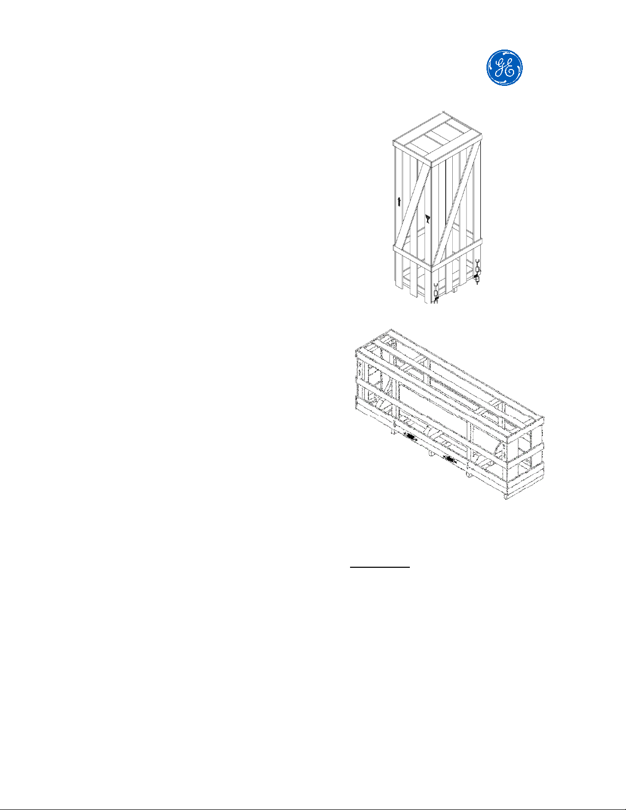
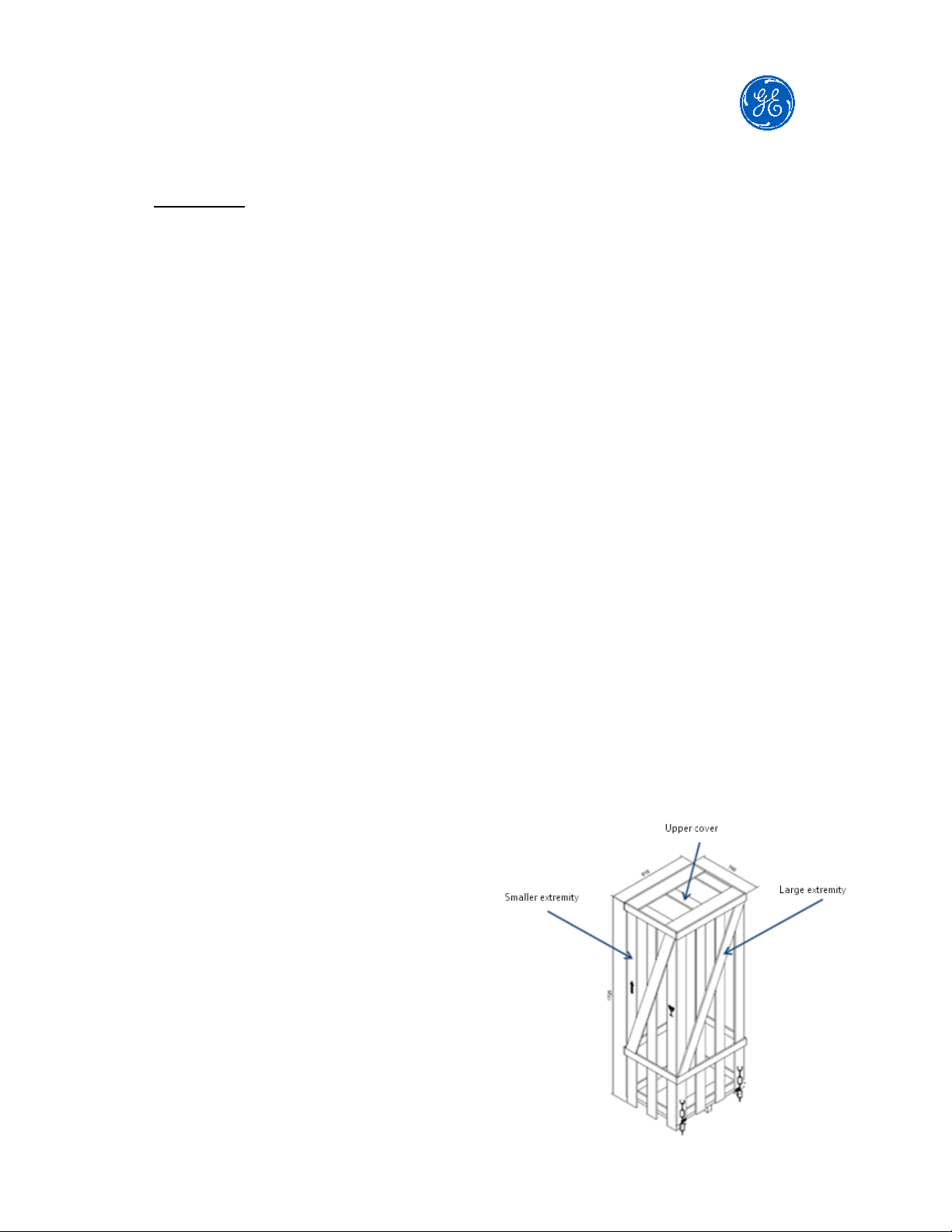
Ver ical packaging
1) Remove upper cover.
2) Remove he smaller ex remi ies.
3) Remove he wood blocking pieces.
4) Remove he larger ex remi ies
5) Remove he four screws a he
equipmen fee and, when applicable,
screws ha anchor he modules o he
package
6) Lif each par of he CVT