Single Units
PANEL DRILLING TEMPLATE
(Viewed from Knob End)
for INSTALLATION OPERATION and MAINTENANCE
INSTRUCTIONS
POWERSTAT®
The right to make
engineering renements
on all products is reserved.
Dimensions and other
details are subject to
change.
Telephone and Fax Numbers
Telephone 860-507-2025
Fax 860-507-2050
Customer Service 860-507-2025, Ext. 70782
Product Application 860-507-2025, Ext. 72058
Toll-Free (in USA and Canada only)
Telephone 1-800-787-3532
Fax 1-800-821-1369
Customer Service 1-800-787-3532, Ext. 70782
Product Application 1-800-787-3532, Ext. 72058
Printed in USA
28 SPRING LANE • SUITE 3 • FARMINGTON, CT 06032 USA
www.superiorelectric.com
ECN 96200
002105-280 REV G
VARIABLE TRANSFORMERS
10C, 10C-40 and 12C Series
INSPECTION
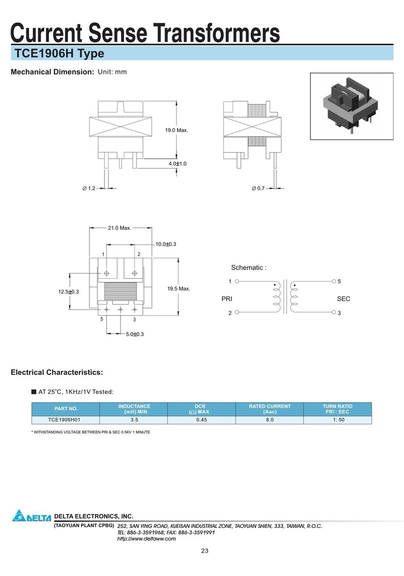
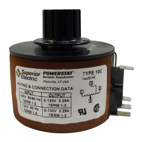
Your new POWERSTAT Variable Transformer has been carefully packed for
shipment. However, damage may occur in transit. After receiving a unit,
check all components (brush contact primarily) to satisfy yourself that there
is no damage. Also make sure that the dial, knob, lock-washer and mounting
nuts are in the package. The “Damage and Shortage” Instructions packed
with the unit outline the proper procedure to follow if any parts are damaged
or missing.
INSTALLATION
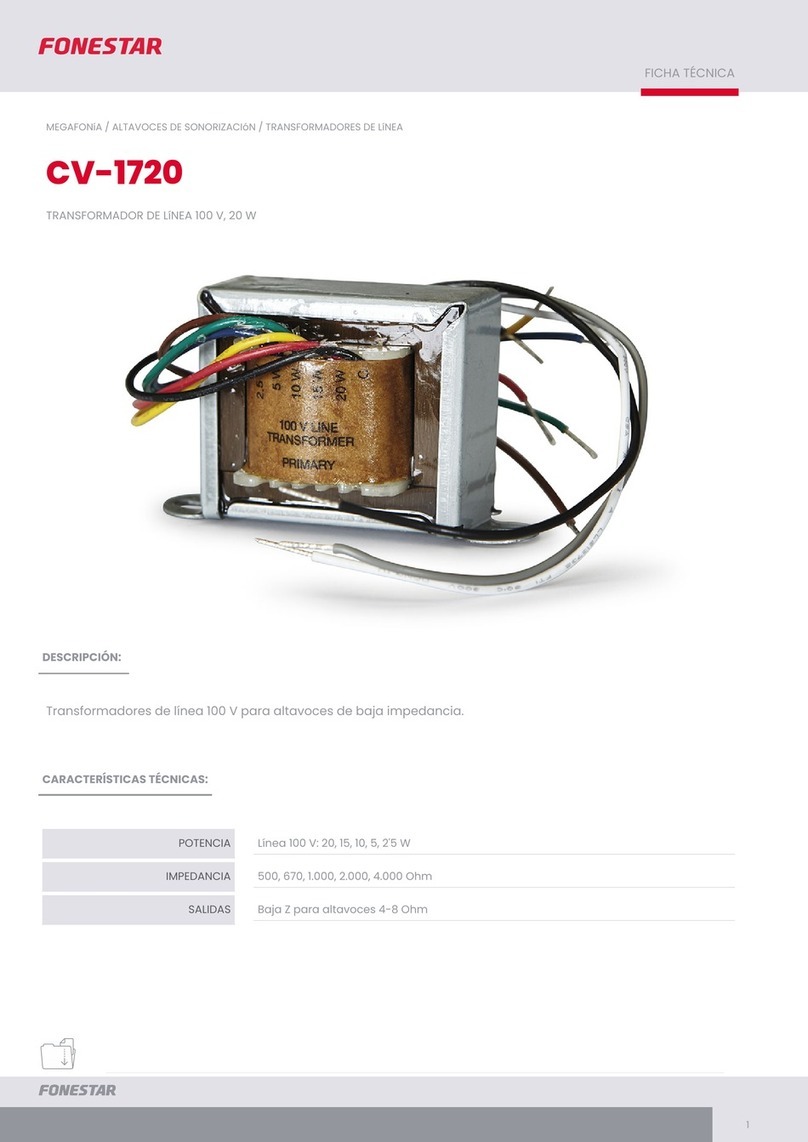
POWERSTAT Variable Transformers of the 10C, 10C-40 and 12C Series are
designed for mounting in the back-of-panel position only.
Single Units
The single hole mounting of single units is fast and simple. For keying to the
panel, a 1/16 inch projection is provided. To facilitate mounting, a drilling
template is supplied as part of these instructions. Actually, the drilling template
must be used only when the hole for the 1/16 inch projection is required.
To mount, proceed as follows:
1. Using the drilling template, locate the panel holes. In order for the
terminals to be on top, the template should be upright. Drill the
holes.
2. Mount the POWERSTAT Variable Transformer as shown. Mount the
unit flush to the back of the panel and the dial flush to the front. A
single nut and lockwasher hold the unit and dial in place. The knob,
when mounted on the shaft, covers the nut and lockwasher.
3. If the unit is not to be keyed to the panel, only the hole for the 3/8
inch center shaft should be drilled. The extra nut provided is placed
on the shaft between the unit and the back of the panel. Otherwise
the mounting is as explained above.
Ganged Assemblies
Ganged units require four panel holes for mounting. Three are needed
for the mounting bolts and a clearance hole is necessary for the center
shaft.
To mount, proceed as follows:
1. Using the drilling template, locate the four panel holes. If the template
is upright the terminals will not be directly on top. When terminals
are required at the top, line marked “T” should be vertical. Drill the
holes.
2. Mount the unit behind the panel as shown using the three ¼”-20
mounting bolts provided. Mount the dial on the front panel, securing
it in place with the 3/8” -32 nut and lockwasher provided. The knob,
when mounted on the shaft covers the nut and lockwasher
MAINTENANCE
When installed and operated in accordance with these instructions, a
POWERSTAT Variable Transformer should require no servicing except
possible replacement of the brush assembly. The brushes should be
inspected periodically and replaced if arcing takes place or if they are
badly worn. Use only the correct Superior Electric replacement brush
assembly. The brushes must be of a special material if proper operation
is to be attained.
REPLACEMENT BRUSH
ASSEMBLIES
Whenever unusual mechanical or electrical difficulties are encountered
in the installation or operation of your POWERSTAT Variable Transformer,
consult Superior Electric.
TYPE PART NO. DESCRIPTION
10C 030098-001 RB10C/RB10B
10C-40 030098-004 RB10C-40/RB10B-40
12C 030098-001 RB12C
Note: 10C and 12C Replacement Brush Assembly are the same.
REPLACEMENT BRUSH ASSEMBLIES

