▪Up to 16 voltage inputs;
▪Up to 16 current inputs;
▪Up to 16 transducer voltage inputs;
▪Up to 16 transducer current inputs;
▪Up to 96 digital inputs;
Note: Maximum capacity of channels depends on boards combination
•Fan-less and no rotating part design
•Waveform recorder at 256 and 512 samples/cycle;
•Disturbance and continuous disturbance at 1, 2 or 4 samples/cycle;
•IRIGB-004 and IEEE 1588 PTPv2
•Trigger using Boolean logic equations;
•GOOSE publisher and subscriber (up to 256 GOOSE inputs)
•MMS report control block publisher
•Cross-trigger using GOOSE messages;
•RS232 serial ports for configuration;
•1 failsafe contact (normally closed dry contact relay);
6Compliance
The device has undergone a range of extensive testing and certification processes to
ensure and prove compatibility with all target markets. A detailed description of these
criteria can be found in the Technical Specifications chapter.
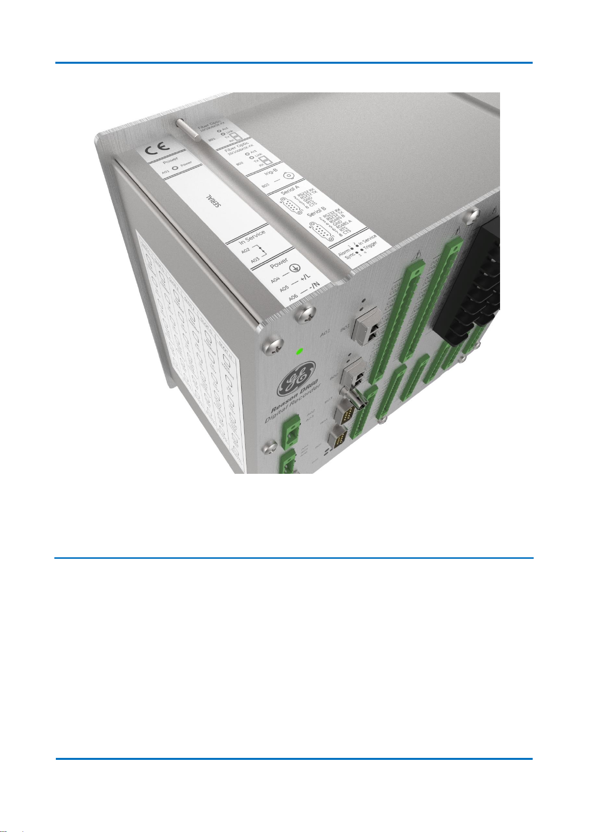
7Functional Overview
It is a single-box solution design for substation environment and offers a very
flexible combination of boards, which allows the customers to have up to 32 analog
inputs and up to 96 binary inputs. These characteristics along with binary outputs options
and two Ethernet ports, make the DR60 ideal to monitor up to 3 bays (considering 8
analog and 16 binary inputs per bay).
The DR60 provides a cost-effective solution for disturbance recording through a
distributed approach. It can be installed locally on a per-feeder basis or interconnected
via peer-to-peer GOOSE messaging that allows cross-triggering to occur without the need
to hard-wire the contacts, providing a scalable solution to station-level recording.
The DR60 complements relays by providing independent, high fidelity waveform
capture. It provides Waveform recorders, SOE and triggered and continuous disturbance
recorders - not typically found even in the most advanced digital relays. It also provides
features such GOOSE publisher and subscriber and MMS report control blocks for
integration with supervisory systems.
8Programs Under the GPL License
The DR60 uses GPL licenses in its implementation according to the following table: