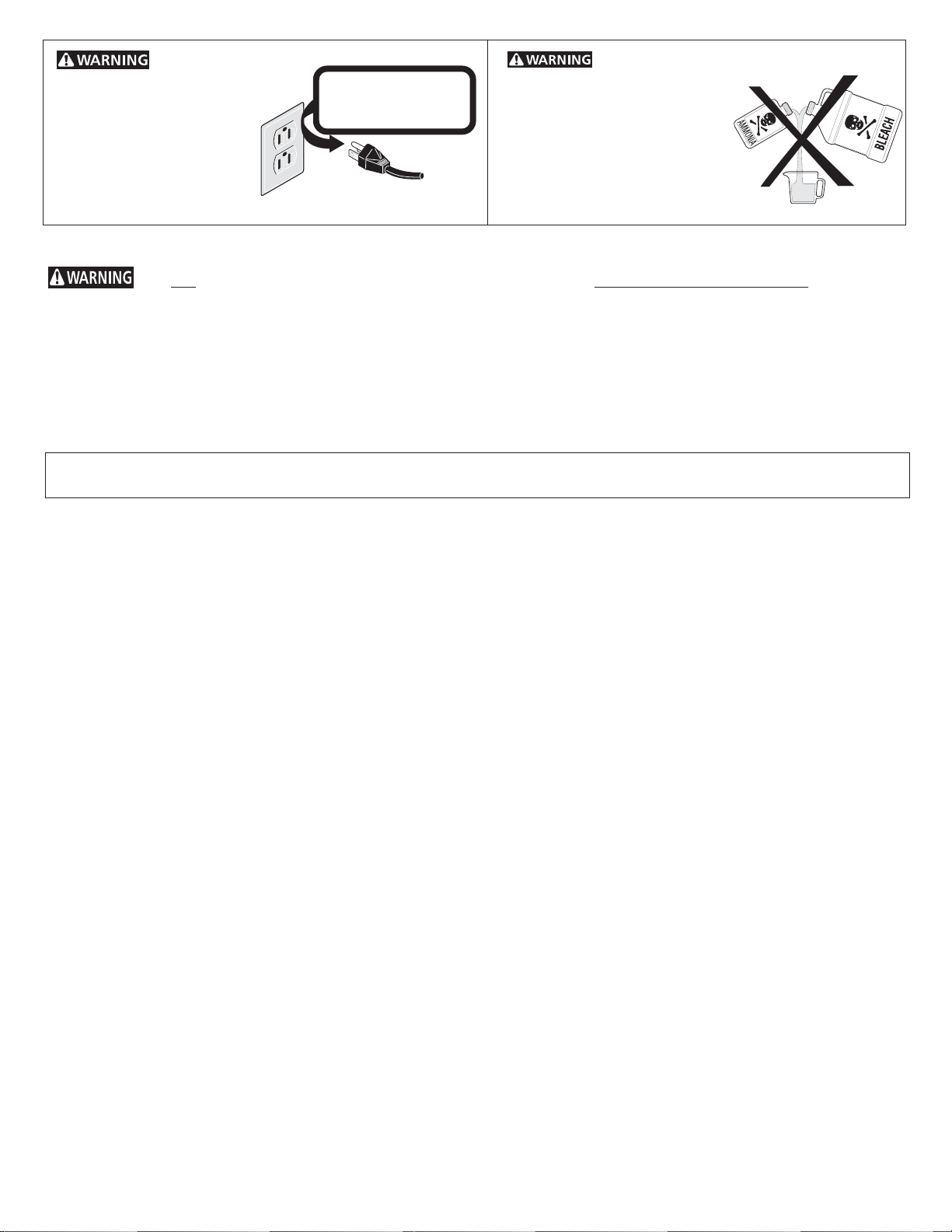
GE Tumble action washer Product information sheet

Coin- Operated Commercial
Tumble Action Washer
Installation Instructions and
Use and Care Guide
P/N 134996400B (0711) www.GEAppliances.com
Machine À Laver Par Culbutage Commerciale
à encaissement automatique
Instructions d’installation et
Guide d’utilisation et d’entretien

2
Before beginning installation, carefully read
these instructions. This will simplify the
installation and ensure the washer is
installed correctly and safely. Leave these
instructions near the washer after
installation for future reference.
NOTE: The electrical service to the washer
must conform with local codes and
ordinances and the latest edition of the
National Electrical Code, ANSI/NFPA 70.
Important Safety Instructions..........................................3
Pre-Installation Requirements.......................................4
Electrical Requirements.................................................4
Grounding Requirements..............................................4
Water Supply Requirements..........................................4
Drain Requirements........................................................4
Location Of Your Washer...............................................4
Rough-In Dimensions....................................................5
Record Coin Box
Key Number__________________________________________
Key number is on key and/or coin box.
You can be killed or seriously injured if you don't immediately follow instructions.
You can be killed or seriously injured if you don't follow instructions.
Product Record
For GE warranty information or to contact a GE Service Center,
call 1-800-GE CARES or www.GEAppliances.com. In Canada
call 1-800-561-3344 or www.geappliances.ca.
If you need SERVICE or PARTS for your GE coin-operated
washer: be ready to give the model number, serial number and
date of purchase. Record below.
Model number________________________________________
Serial number_________________________________________
Purchase date_________________________________________
For your safety the information in this manual must be followed to minimize the risk of fire or explosion or to prevent
property damage, personal injury or loss of life.
- Do not store or use gasoline or other flammable vapors and liquid in the vicinity of this or any other appliance.
- WHAT TO DO IF YOU SMELL GAS
·Do not try to light any appliance.
·Do not touch any electrical switch; do not use any phone in your building.
·Clear the room, building or area of all occupants.
·Immediately call your gas supplier from a neighbor’s phone. Follow the gas suppliers instructions.
·If you cannot reach your gas supplier, call the fire department.
Installation and service must be performed by a qualified installer, service agency or the gas supplier.
WASHER SAFETY
Your safety and the safety of others is very important. We have provided many important safety messages in the Installation
Instructions/Use & Care Guide and on your appliance. Always read and obey all safety messages.
This is the safety alert symbol. This symbol alerts you to hazards that can kill or hurt you or others. All safety messages will be
preceded by the safety alert symbol and the word "DANGER" or "WARNING". These words mean:
All safety messages will identify the hazard, tell you how to reduce the chance of injury, and tell you what can happen if the
instructions are not followed.
DANGER
TABLE OF CONTENTS
Unpacking.......................................................................6
Installation..................................................................6-7
Coin slide installation................................................7-9
Meter case instructions.................................................9
Replacement Parts..........................................................10
Parts lists....................................................................10-12
Consumer Support................................................13-14
Français..................................................................15-27
NOTE: The instructions appearing in this
INSTALLATION AND SAFETY INSTRUCTIONS
manual are not meant to cover every possible
condition and situation that may occur. Common
sense and caution must be practiced when
installing, operating and maintaining any
appliance.
Your washer is equipped with a door safety interlock. Verify proper operation of interlock system daily, using the following procedure:
1. With the washer door open, insert the required number of coins and press theSTART button. THE WASHER MUST NOT START!
2. Close the washer door. Press the START button again to start the machine. Attempt to open the door, without exerting excessive
force. THE DOOR MUST NOT OPEN!
IF THE WASHER STARTS WITH THE DOOR OPEN, OR THE DOOR CAN BE OPENED WHILE THE WASHER IS OPERATING, THE
MACHINEMUSTIMMEDIATELYBETAKENOUTOFSERVICE.DISCONNECTTHEPOWERCORD,ANDMARKTHEMACHINE"OUT
OF ORDER", UNTIL THE INTERLOCK SYSTEM IS REPAIRED, AND OPERATES AS DESCRIBED ABOVE.

3
Grounding type
w
all receptacle
Power supply
cord with 3-prong
grounding plug
Do not under
any circumstances
cut, remove,
or bypass
the grounding prong
from this plug.
Do not use or mix
liquid chlorine bleach with
other household chemicals
such as toilet cleaners, rust
removers, acid or products
containing ammonia. These
mixtures can produce
dangerous fumes which can
cause serious injury or death.
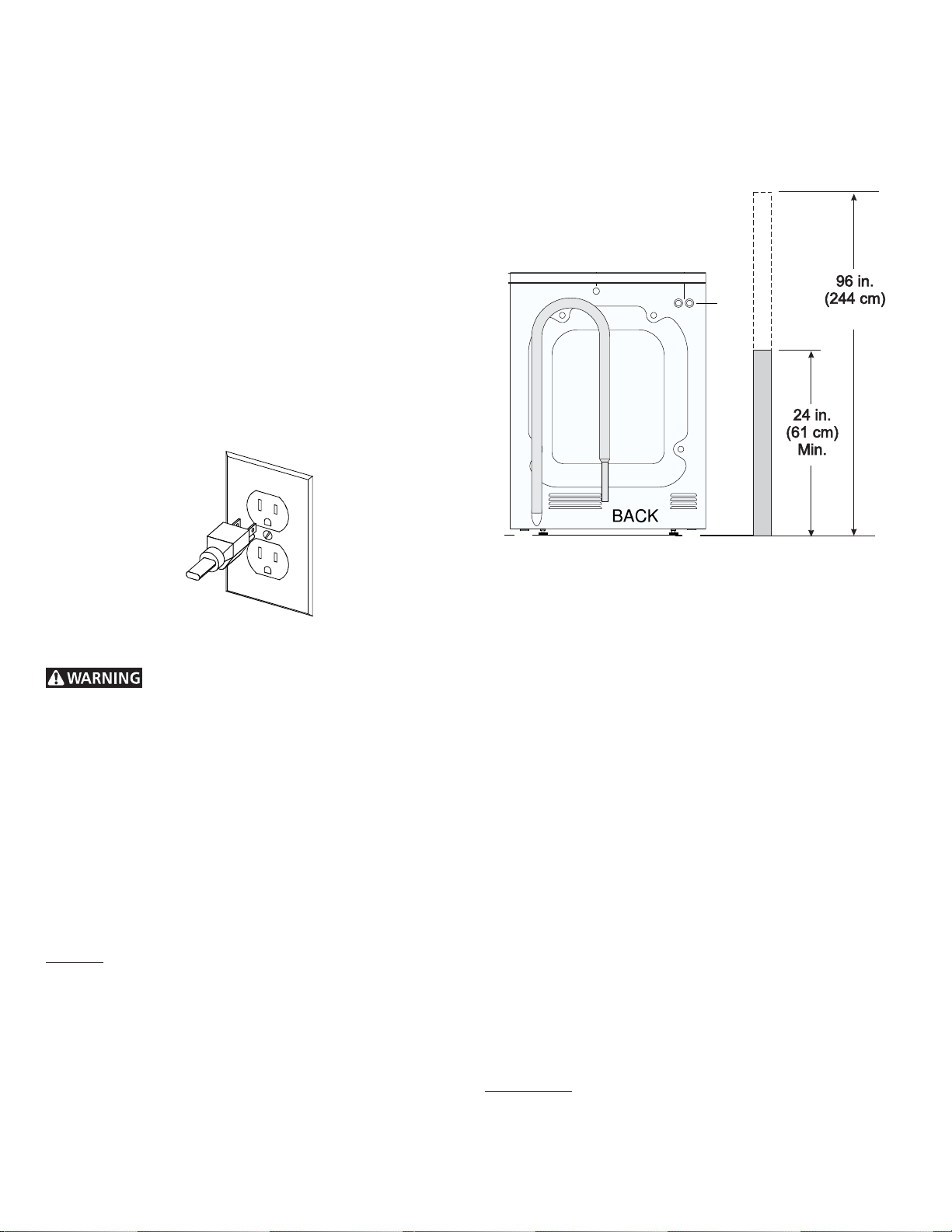
Avoid fire
hazard or electrical shock.
Do not use an adaptor plug
or extension cord or
remove grounding prong
from electrical power cord.
Failure to follow this
warning can cause serious
injury, fire or death.
Read all instructions before using this washer.
Important Safety Instructions
CORRECT Use this way ONLY
You can be killed or seriously injured if you don't follow these Important Safety Instructions:
• To reduce the risk of fire, electrical shock, or injury to persons when using this washer, comply with the basic warnings listed below.
• Failure to comply with these warnings could result in serious personal injuries.
Prevent Fire
• Do not wash items that have been previously cleaned in, soaked in, or spotted with gasoline, cleaning solvents, kerosene, cooking
oils, waxes, etc. Do not store these items on or near the washer. These substances give off vapors or chemical reactions that could
ignite or explode.
• Do not put oily or greasy rags or clothing on top of the washer. These substances give off vapors that could ignite the materials.
• Do not add gasoline, cleaning solvents, or other flammable or explosive substances to the wash water. These substances give
off vapors that could ignite or explode.
FOR YOUR SAFETY Do not store or use gasoline or other flammable vapors or liquids in the vicinity of this or
any other appliance.
• Under certain conditions, hydrogen gas may be produced in a hot water system that has not been used for 2 weeks or more.
HYDROGEN GAS IS EXPLOSIVE. If the hot water system has not been used for such a period, before using the washer, turn
on all hot water faucets and let the water flow from each for several minutes. This will release any accumulated hydrogen gas.
Hydrogen gas is flammable; do not smoke or use an open flame during this time.
• Failure to comply with these warnings could result in fire, explosion, serious bodily injury and/or damage to the rubber or plastic
parts of the washer.
Protect Children
• Do not allow children to play on or in the washer. Close supervision of children is necessary when the washer is used near children.
As children grow, teach them the proper, safe use of all appliances.
• Destroy the carton, plastic bag and other packing materials after the washer is unpacked. Children might use them for play. Cartons
covered with rugs, bedspreads or plastic sheets can become airtight chambers.
• Keep laundry products out of children's reach. To prevent personal injury, observe all warnings on product labels.
• Before the washer is removed from service or discarded, remove the washer lid to prevent accidental entrapment.
• Failure to comply with these warnings could result in serious personal injuries.
Prevent Injury
• Test door interlock system daily. Follow instructions on previous page.
• To prevent shock hazard and assure stability during operation, the washer must be installed and electrically grounded by a qualified
service person in accordance with local codes. Refer to INSTALLATION AND SAFETY INSTRUCTIONS for detailed grounding
procedures. If the washer is moved to a new location, have it checked and reinstalled by a qualified service person.
• To prevent personal injury or damage to the washer, the electrical power cord of the washer must be plugged into a properly
grounded and polarized 3-prong outlet. The third grounding prong must never be removed. Never ground the washer to
a gas pipe. Do not use an extension cord or an adaptor plug.
• Follow package directions when using laundry products. Incorrect usage can produce poisonous gas--resulting in serious injury
or death.
- Do not combine laundry products for use in 1 load unless specified on the label.
- Do not mix chlorine bleach with ammonia or acids such as vinegar.
• To prevent serious personal injury and damage to the washer:
- All repairs and servicing must be performed by an authorized servicer unless specifically recommended in this
INSTALLATION AND SAFETY INSTRUCTIONS manual. Use only authorized factory parts.
- Do not tamper with controls.
- Do not install or store the washer where it will be exposed to the weather.
•To reduce the risk of electric shock, disconnect this appliance from the power supply before attempting any user maintenance.
Turning the controls to the OFF position does not disconnect this appliance from the power supply.
• To prevent injury, do not reach into the washer while parts are moving. Before loading, unloading or adding items, push in the cycle
selector knob and allow the tub to coast to a complete stop before reaching inside.
• Failure to comply with these warnings could result in serious personal injuries.
• This washer is equipped with an electrical overload protector. The motor will stop if it becomes overheated. The washer will
automatically restart after a cool down period of up to 30 minutes, if the washer has not been manually turned off during this time.
SAVE THESE INSTRUCTIONS
3
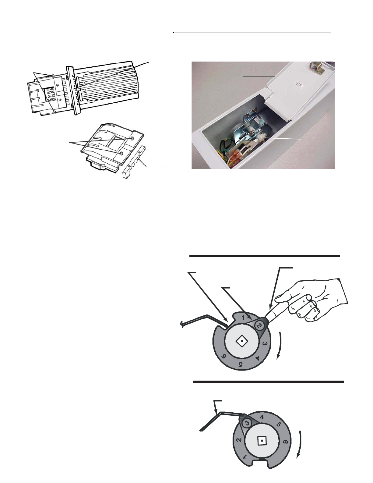
Grounding type wall receptacle
Do not under any
circumstances cut, remove,
or bypass the grounding
prong from this plug.
Power supply cord with
3-pronggroundingplug

4
GROUNDING REQUIREMENTS
Improper connection of the equipment grounding
conductor can result in a risk of electrical shock. Check with a
licensed electrician if you are in doubt as to whether the appliance
is properly grounded.
1. The washer MUST be grounded. In the event of malfunction
or breakdown, grounding will reduce the risk of electrical
shock by a path of least resistance for electrical current.
2. Since your washer is equipped with a power supply cord
having an equipment-grounding conductor and a grounding
plug, the plug MUST be plugged into an appropriate, copper
wired receptacle that is properly installed and grounded in
accordance with all local codes and ordinances or in the
absence of local codes, with the National Electrical Codes,
ANSI/NFPA 70 (latest edition). If in doubt, call a licensed
electrician.
DO NOT cut off or alter the grounding prong on the power supply
cord. In situations where a two-slot receptacle is present, it is the
owner’s responsibility to have a licensed electrician replace it
with a properly grounded three prong grounding type
receptacle.
WATER SUPPLY REQUIREMENTS
Hot and cold water faucets MUST be installed within 42 inches
(107 cm) of your washer’s water inlet. The faucets MUST be 3/4
inch (1.9 cm) garden hose type so inlet hoses can be connected.
Water pressure MUST be between 10 and 120 pounds per square
inch (maximum unbalance pressure, hot vs. cold, 10 psi.) Your
water department can advise you of your water pressure. 4
Max.Max.
Max.Max.
Max.
DRAIN REQUIREMENTS
Models equipped with drain pump:
1. Drain MUST be capable of eliminating 17 gals (64.3 L) per
minute.
2. A standpipe diameter of 1-1/4 in. (3.18 cm) minimum.
3. The standpipe height above the floor should be:
NOTE:
Drain hose attached to the washer can reach a 58 in. (147 cm)
high standpipe. For higher standpipe use hose P/N 134592701,
available from an authorized parts distributor. If drain is less
than 24 in. (61 cm), install a siphon break kit, available at your
local hardware store.
Models equipped with gravity drain:
1. Floor drain MUST be capable of eliminating 17 gals (64.3 L)
per minute.
2. Floor drain diameter must be at least 1/2 inch larger than
drain hose.
LOCATION OF YOUR WASHER
See rough-in dimensions on the next page (Figure 1).
DO NOT INSTALL YOUR WASHER:
1. In an area exposed to dripping water or outside weather
conditions. The ambient temperature should never be below
60 degrees F (15.6 degrees C) for proper washer operation.
2. In an area where it will come in contact with curtains or
drapes.
3. In an area (garage or garage-type building) where gasoline
of other flammables are kept or stored (including
automobiles).
4. On carpet. Floor MUST be solid with a maximum slope of
1/2 in. per foot (1.27 cm per 30.5 cm). To ensure vibration or
movement does not occur, reinforcement of the floor may
be necessary.
IMPORTANT MINIMUM INSTALLATION CLEARANCES
When installed in alcove: Sides, Rear, Top = 0 in (0 cm).
When installed in closet: Sides, Rear, Top = 0 in (0 cm),
Front = 1 in (2.54 cm).
Closet door ventilation openings required: 2 louvers each 60 in²
(387 cm²) - 3 in (7.6 cm) from top and bottom of door.
PRE-INSTALLATION REQUIREMENTS
Tools Required for Installation:
1. 1/4 in. nut driver
2. 3/8 in. socket with ratchet.
3. 3/8 in. open end wrench.
4. 7/16 in. socket with ratchet.
5. 9/16 in. open end wrench.
6. Channel-lock adjustable pliers.
7. Carpenter’s level.
ELECTRICAL REQUIREMENTS
CIRCUIT - Individual, properly polarized and grounded 15 amp.
branch circuit fused with 15 amp. time delay fuse or circuit breaker.
POWER SUPPLY - 2 wire, with ground, 120 volt, single phase, 60
Hz, Alternating Current. NOTE: The use of this washer with power
created by gas powered generators, solar powered generators,
wind powered generators or and other generator other than the
local utility company is not recommended.
OUTLET RECEPTACLE - Properly grounded 3-prong receptacle to
be located so the power supply cord is accessible when the washer
is in an installed position. NOTE: GFI (Ground Fault Interrupter)
receptacle is not required.

5
ROUGH-IN DIMENSIONS
SIDE
POWER
CORD
inch (cm)
Ò
Ñ
8
43/8
<>
v
^
(11.2)
(20.4)
BACK
UNDER
COUNTER
WATER
INLETS
inch (cm)
5
>
17
(43.2)
<
(Figure 1).

6
UNPACKING
1. Cut the shipping carton along the dotted line along the base
of the unit.
2. While in the carton carefully lay the washer on its back
side.
3. Removethe styrofoam base.
4. Carefully return the washer to an upright position and remove
the carton.
5. Carefully move the washer to within 4 feet (122cm) of the
final location.
6. Remove the following from the back side of the washer:
3 bolts,
3 yellow plastic spacers,
2 or 3 metal "P" clamps.
7. Remove the service panel from the front of the washer.
8. Remove the 4 nuts and 6 large washers that attach the 2
yellow shipping braces to the drum and the base. Lift up on
the drum and remove the braces (a yellow ribbon surrounds
the items to be removed). These braces must be removed to
allow the power supply cord to be released from the shipping
ring.
BOLT
SPACER
"P" CLAMP
INSTALLATION
1. Run some water from the hot and cold faucets to flush the
water lines and remove particles that might clog up the water
valve screens.
2. Remove the inlet hoses and rubber washers from the plastic
bag and install the rubber washers in each end of the inlet
hoses.
3. Carefully connect the inlet hose marked "HOT" to the outside
"H" outlet of the water valve. Tighten by hand, then tighten
another 2/3 turn with pliers. Carefully connect the other
inlet hose to the inside "C" outlet of the water valve. Tighten
by hand, then tighten another 2/3 turn with pliers. Do not
crossthread or over-tighten these connections.
4. Connect the inlet hose ends to the HOT and
COLD water faucets tightly by hand, then
tighten another 2/3 turn with pliers. Turn the
water on and check for leaks.
9. Remove the large styrofoam block located under the drum.
Lift up on the drum, tilt the base of the foam block inwards
toward the rear of the washer until free, then pull it out.
10. Remove and discard the yellow ribbon and label from the
front of the washer.
11. From the rear of the washer, carefully pull out the power
supply cord through the hole in the backsheet.
12. Replace the service panel and screws.
NOTE: If the washer is to be transported at a later date, the
shipping support hardware must be reinstalled to prevent
shipping damage.

7
Cable
Tie
FIGURE 2
5. On machines equipped with drain pump, form
a U shape on the end of the drain hose, with
the hose pointed toward the drain.
NOTE: If the drain hose is placed in a standpipe
without forming a U shape, a siphoning action
could occur. There must be an air gap around
the drain hose. A snug hose fit can also cause a
siphoning action.
6. Carefully move the washer to its final location.
NOTE: Do not use the dispenser drawer or door to lift washer.
Excessive noise and vibration can be prevented by properly
leveling the washer.
7. For free standing installation and with the washer in it’s final
position, place a level on top of the washer. Adjust the
leveling legs so the washer is level front-to-rear and side-to-
side, and stable corner-to-corner.
Press down on alternate corners and sides and feel for the
slightest movement. Adjust the appropriate leg so the
washer is SOLID on the floor on ALL four legs. Keep the
leveling leg extension at a minimum for best performance of
thewasher.
8. For pedestal installations, See additional installation
instructions included with the pedestal.
9. Plug the power cord into a grounded outlet.
NOTE: Check to ensure the power is off at the circuit breaker/
fuse box before plugging the power cord into an outlet.
10. Turn on the power at the circuit breaker/fuse box.
11. Be sure you have read the "Important Safety Instructions"
before operating this washer.
12. Run the washer through a complete cycle. Check for water
leaks and proper operation.
13. Keep these instructions for future reference.
NOTE: A wiring diagram is located inside the washer on the
side panel.
FIGURE 1
COIN BOX ADJUSTMENT
The tight fit of the money box is set at the factory. Customer may
loosen fit as desired by loosening the slotted nuts. See FIG.2.
Keep A record of all coin-box key numbers.
A lost key can only be replaced by ordering the key numbers from
the place were the unit was purchased. The key number is located
both on the key and behind the end panel of the coin box. If the
key number is not available, the lock must be drilled out to remove
the coin box.
Instructions for Changing Vend Price
TOOLS NEEDED
• Medium sized slotted screwdriver
• Small slotted Phillips screwdriver
Place all screws and other items removed from coin slide assembly
on a cloth so they will not get lost.
STEP 1
Remove slide mechanism from meter case. (see FUGURE 1).
STEP 2
Remove the coin slide extension from coin slide by removing two
mounting screws and spacers
(see FIGURE 2).
Slide Return Spring
FIGURE 2
(2) Mounting Screws
and Spacers
7

8
8
(2) Slide Stop
Screws FIGURE 3
(1) Receiver Block Screw
Spare Parts
Compartment
and Screw
Coin Receiver
Block
FIGURE 4
FIGURE 5
FIGURE 6
NOTE:
Black
colored
slots are
closed off
by block-
out key.
• Pull coin slide out of coin chute (see FIGURE 4).
STEP 4
Turn coin slide upside down and remove screw that holds coin receiver
block (see FIGURE 5).
STEP 5
Remove coin receiver block from coin slide (see FIGURE 6):
• Turn coin slide right side up. Keep coin receiver block in place with
your fingers.
• Carefully lift coin slide from coin receiver block. If necessary, shake
coin slide gently to loosen block.
STEP 3
Remove coin slide from coin chute:
• Unhook and remove the coin slide return spring. (see FIGURE 2).
• Turn coin slide mechanism upside down.
• Remove coin slide stop by taking out two screws to the chute bottom
(see FIGURE 3).
Ratchet
Dog and
Spring
Block-Out
Keys
FIGURE 8
FIGURE 7
VEND
PRICE COIN SLOTS
1 2 3 4 5 6 7 8
$.10
0
$.20
$.25
$.35
$.45
$.50
$.60
$1.00
$2.00
$1.10
$1.25
$1.35
$1.50
$1.60
$1.75
$1.85
$1.70
$1.45
$1.20
$.95
$.85
$.75
$.70
TABLE OF VEND PRICE
To remove block-out keys, pull straight up.
NOTE: Be sure block-out keys and /or dime inserts are
seated properly and ratchet dog is in place with irs spring
connected (see FIGURE 8).
Be sure the proper coin sizing block is in place.
STEP 6
Set new vend price by adding or removing the appropriate
block-out keys and/or dime inserts according to th Table
of Vend Prices
(see FIGURE 7).

9
Anti-Cheat
Gate
(2) Upper Coin
Chute Cover
Screws
FIGURE 9
9
(2) Coin Sizing
Block Screws
Coin Sizing
Block
FIGURE 10
Change coin sizing block:
• Remove two screws that hold upper coin chute cover.
Remove cover (see FIGURE 9).
• Remove two screws that hold coin sizing block to upper
coin chute cover cover (see FIGURE 10).
• Put new coin sizing block in place. Reinsert and tighten
mounting screws.
• Replace coin chute cover. Reinsert and tighten screws.
STEP 7
Replace coin receiver block into slide:
• Hold coin receiver right side up in the palm of one hand.
• Lower coin slide until coin receiver block fits into the
coin slide cavity. CAUTION: Do not dislodge ratchet
dog and spring.
• Hold coin receiver block in place with your fingers and
turn slide upside down.
• Insert and tighten screw.
STEP 8
Install slide into coin chute. Slide can only be pushed in if
the anti-cheat gate in flange is pushed to the left. (see
FIGURE 9).
STEP 9
Replace coin slide stop with two screws. Replace coin
slide return spring. Replace coin slide extension with two
screws (be sure spacers are in place).
STEP 10
Replace coin slide mechanism in meter case. Replace and
tighten coin slide mounting bolt.
NOTE: It may be easier to insert coin slide mounting bolt if
you remove the timer from the mounting screws temporarily.
Meter Case Instructions
INSTRUCTIONS TO CHANGE THE NUMBER OF COIN SLIDE
INSERTIONS TO START APPLIANCE.
1. Disconnect power from machine.
2. Remove meter-case service door. (Fig.1)
3. Turn Shaft & Cam Assembly in a clockwise direction until switch
lever arm drops into cam notch (Fig. 2).
4. Lift Adjusting Tab away from cam with finger and turn Tab to desired
number. Make sure Tab\ locks into place in new position.
5. Turn Shaft & Cam Assembly in a clockwise direction until switch
lever arm is on top of Tab to assure that both mechanism switches
are open (Fig. 3).
6. Replace meter-case service door and reconnect power to machine.
CAM NOTCH
ADJUSTMENT
USE FINGER
TO LIFT
TA B
CLOCKWISE
E
DIRECTION
FIGURE
7
7
SWITCH LEVER ARM
TO LIFT PAD
EXAMPLE: To change from $1 to $2 move tab from 1 to 2.
FIGURE2
FIGURE3
Remove
meter-case
service door
FIGURE1
Shaft and
cam
assembly

10
ITEM REQ’D PART NO DESCRIPTION
1 2 00-7185 #4-40 SELF-TAPPING
SC.
2 1 76-6009-* TIMER MOTOR ASS’Y
3 1 76-1037 SWITCH & BRACKET
SUB-ASS’Y
4 1 76-5014 DRIVE SELEEVE
5 1 76-2033 SLEEVE
6 1 00-8149 TORSION SPRING
7 3 00-7070 RETAINING RING
8 2 76-5013 DRIVE BUSHING
9 1 00-8003 SPRING
10 1 76-1036 RACTHETARM & PAWL
ASM’Y
11 1 76-5017 RACHET WHEEL
12 1 76-2003 WASHER
13 1 59-204 SPRING
14 1 76-5012 CAM
15 1 76-5010 ADJUSTER TAB
16 1 00-7055 SPRING WASHER
17 1 00-7047 WASHER
18 1 76-2026 DRIVE SHAFT
19 2 00-7458 #4-40 3/16 PAN HD SC.
20 2 00-7097 #4 SPLIT
LOCKWASHER
21 1 00-6189 SNAP SWITCH
22 1 00-6190 SNAP SW. & LEVER
ARM ASM’Y
23 1 76-5009 SWITCH INSULATOR
24 1 76-2035 NUT PLATE
25 1 76-6000 WIRE HARNESSASS’Y
26 2 02-0810-00 #8-32x5/16 SEMS
SCREW
27A 1 76-2059 MOUNTING BRACKET
27B 1 76-2027 MOUNTING BRACKET
28 1 59-0314 CABLE TIE
29 1 58-172-* GROUND WIRE
30 1 00-7558 WASHER
Item 27A: Models 76-1030-21 (115v-60Hz),
76-1030-22 (230v-60Hz)
Item 27B: Models 76-1030-11 (115v-60Hz),
76-1030-12 (230v-60Hz)
Parts List for series 7682 “Quick-Change” Start Mechanism
REPLACEMENT PARTS
If replacements parts are needed for your washer, contact the source where you purchased your washer or call 1-800-GE CARES for
the GE Authorized Parts Distributor nearest you. For coin box parts, call 1-800-221-0982, Greenwald Industries.
Destroy the carton and plastic bags after the washer is unpacked. Children might use them for play. Cartons covered
with rugs, bedspreads, or plastic sheets can become airtight chambers causing suffocation. Place all materials in a garbage container
or make materials inaccessible to children.
The instructions in this manual and all other literature included with this washer are not meant to cover every possible
condition and situation that may occur. Good safe practice and caution MUST be applied when installing,operating and maintaining
any appliance.
Maximum benefits and enjoyment are achieved when all the Safety and Operating instructions are understood and practiced
as a routine with your laundering tasks.

11
20-3020 20-3000
V8 Parts List
DESCRIPTION REQ. 20-3020 20-3000
————————————————————————————
1 SCREW (METRIC) 2 00-9724 00-7924
————————————————————————————
2 SCREW (METRIC) 2 00-7938 00-7938
————————————————————————————
3 TOP HOUSING 1 20-3019 20-3002
————————————————————————————
4 SHIM 2 20-2042 -----------
————————————————————————————
5 COIN SIZING BLOCK 1 20-3006 20-3006
————————————————————————————
6 GATE COVER 1 20-2043 20-2006
————————————————————————————
7 GATE 1 20-2035 20-2000
————————————————————————————
8 SLIDE STOP DOG 8 20-2011 20-2011
————————————————————————————
9 DOG SHAFT 1 20-4004 20-4000
————————————————————————————
10 DECAL,CASTING 1 00-9905 00-9905
————————————————————————————
11 BODY CASTING 1 20-3020 20-3000
————————————————————————————
12 COIN SLIDE 1 20-3021 ------------
————————————————————————————
13 DECAL, SLIDE 1 00-9104 00-9104
————————————————————————————
14 CHUTE LOCATING SCREW 4 00-7483 61-55
————————————————————————————
15 SLIDE RETURN SPRING 1 00-8148 00-8148
————————————————————————————
DESCRIPTION REQ. 20-3020 20-3000
————————————————————————————
16 SPRING 1 20-2040 20-2001
————————————————————————————
17 SPRING PROTECTOR 1 20-2038 20-2007
————————————————————————————
18 RACK 1 20-2023 20-2005
————————————————————————————
19 SCREW (METRIC) 2 00-7931 00-7931
————————————————————————————
20 10¢ INSERT varies 20-3023 20-5001
————————————————————————————
21 SCREW (METRIC) 2 00-7923 00-7929
————————————————————————————
22 SLIDE STOP 1 20-2039 20-2004
————————————————————————————
23 RATCHET DOG SPRING 1 00-8123 00-8123
————————————————————————————
24 BLOCKOUT KEY varies 20-5002 20-2010
————————————————————————————
25 SLIDE RATCHET DOG 1 20-2041 20-2008
————————————————————————————
26 STORAGE COMP. COVER 20-2037 20-2003
————————————————————————————
27 SCREW (METRIC) 2 00-7935 -----------
————————————————————————————
28 BUFFER 1 20-2034 ----------
————————————————————————————
29 RATCHET DOG POST 1 20-4005 -----------
————————————————————————————
30 COIN RETAINER optional Opt. 00-8168 ------------
————————————————————————————
DESCRIPTION REQ. 20-3020 20-3000
————————————————————————————
31 COIN SIZING BLOCK varies 20-3007 20-3007
————————————————————————————
32 PRESSURE SPRING ASMY Opt. 20-1012 20-1012
————————————————————————————
33 MAGNET Opt. 00-9256 00-9256
————————————————————————————
34 SHIELD Opt. 20-2045 20-2045
————————————————————————————
35 COIN RECEIVER BLOCK 1 --------- 20-2003
————————————————————————————
37 LOCK WASHER 1 --------- 00-7934
————————————————————————————
38 SCREW (METRIC) 1 --------- 00-7933
————————————————————————————
39 SCREW (METRIC) 1 --------- 00-7932
————————————————————————————
40 SCREW 00-7541 00-7541
————————————————————————————
41 TOP HOUSING ASMY 20-1103-1 20-1104-1
————————————————————————————
V8 Coin Chute Parts List

12
Notes
______________________________________________________________________________________________________
______________________________________________________________________________________________________
______________________________________________________________________________________________________
______________________________________________________________________________________________________
_______________________________________________________________________________________________________
_______________________________________________________________________________________________________
_______________________________________________________________________________________________________
______________________________________________________________________________________________________
_______________________________________________________________________________________________________
______________________________________________________________________________________________________
________________________________________________________________________________________________________
________________________________________________________________________________________________________________________________________________________________
_______________________________________________________________________________________________________
_______________________________________________________________________________________________________
________________________________________________________________________________________________________
_______________________________________________________________________________________________________
______________________________________________________________________________________________________
_______________________________________________________________________________________________________
________________________________________________________________________________________________________
_______________________________________________________________________________________________________
_______________________________________________________________________________________________________
________________________________________________________________________________________________________
_______________________________________________________________________________________________________
NEW VEND PRICE
____________________________________________________________
Order Form
Tochangevendprice, detachandmail thelowerportionto:
Customer Service Department
Greenwald Industries Inc.
212 Middlesex Ave.
Chester, CT 06412
____________________________________________________
The coin chute has been pre-set at the factory.
When increasing in $.25 pricing
Followproductinformation instructions;noextra partsrequired.
When decreasing in $.25 pricing - or - changing to
$.10 pricing.
(Coinsizingblockrequired; see"ChangingVend Price"
section.)
Orderrequiredparts usingthistear-off. Block-outkeyswillbe
shippedtoyouatno charge. Follow product information
instructions.
Quantity____________________________________________________
Existing Vend Price_________________________________________
Name_____________________________________________________
Company_________________________________________________
Address__________________________________________________
City_______________________________________________________
State/Zip__________________________________________________
Daytime phone_____________________________________________
Purchase date_____________________________________________

24
Consumer Support.
GE Appliances Website ge.com
Have a question or need assistance with your appliance? Try the GE Appliances Website 24 hours a day,
any day of the year! For greater convenience and faster service, you can now download Owner’s Manuals,
order parts or even schedule service on-line.
Schedule Service ge.com
Expert GE repair service is only one step away from your door. Get on-line and schedule your service at your
convenience 24 hours any day of the year! Or call 800.GE.CARES (800.432.2737) during normal business hours.
Real Life Design Studio ge.com
GE supports the Universal Design concept—products, services and environments that can be used by people of all
ages, sizes and capabilities. We recognize the need to design for a wide range of physical and mental abilities and
impairments. For details of GE’s Universal Design applications, including kitchen design ideas for people with
disabilities, check out our Website today. For the hearing impaired, please call 800.TDD.GEAC (800.833.4322).
Extended Warranties ge.com
Purchase a GE extended warranty and learn about special discounts that are available while your warranty is still
in effect. You can purchase it on-line anytime, or call 800.626.2224 during normal business hours. GE Consumer
Home Services will still be there after your warranty expires.
Parts and Accessories ge.com
Individuals qualified to service their own appliances can have parts or accessories sent directly to their homes
(VISA, MasterCard and Discover cards are accepted). Order on-line today, 24 hours every day or by phone at
800.626.2002 during normal business hours.
Instructions contained in this manual cover procedures to be performed by any user. Other servicing generally should be
referred to qualified service personnel. Caution must be exercised since improper servicing may cause unsafe operation.
Contact Us ge.com
If you are not satisfied with the service you receive from GE, contact us on our Website with all the details
including your phone number, or write to: General Manager, Customer Relations
GE Appliances, Appliance Park
Louisville, KY 40225
Register Your Appliance ge.com
Register your new appliance on-line—at your convenience! Timely product registration will allow for enhanced
communication and prompt service under the terms of your warranty, should the need arise. You may also
mail in the pre-printed registration card included in the packing material.

Consumer Support.
GE Appliances Website GEAppliances.ca
Have a question or need assistance with your appliance? Try the GE Appliances Website 24 hours a day,
any day of the year! For greater convenience and faster service, you can now download Owner’s Manuals,
order parts, catalogs, or even schedule service on-line. You can also “Ask Our Team of Experts™” your questions,
and so much more...
Schedule Service 1.800.561.3344 or GEAppliances.ca
Expert GE repair service is only one step away from your door. Get on-line and schedule your service at your
convenience 24 hours any day of the year! Call 1.800.561.3344 during normal business hours.
Real Life Design Studio
GE supports the Universal Design concept---products, services and environments that can be used by people of all
ages, sizes and capabilities. We recognize the need to design for a wide range of physical and mental abilities and
impairments. For details of GE’s Universal Design applications, including kitchen design ideas for people with
disabilities, check out our Website today.
In Canada, contact: Manager, Consumer Relations, Camco, Inc.
Suite 310, 1 Factory Lane
Moncton, N.B. E1C 9M3
Extended Warranties 1.888.261.2133 or GEAppliances.ca
Purchase a GE extended warranty and learn about special discounts that are available while your warranty is still
in effect. You can purchase it on-line anytime, or call 1.888.261.2133 during normal business hours. GE Consumer
Home Services will still be there after your warranty expires.
Parts and Accessories 1.800.661.1616 or GEAppliances.ca
Individuals qualified to service their own appliances can have parts or accessories sent directly to their homes
(VISA, MasterCard and Discover cards are accepted). Order on-line today, 24 hours every day or by phone at
1.800.661.1616 during normal business hours.
Instructions contained in this manual cover procedures to be performed by any user. Other servicing generally should be
referred to qualified service personnel. Caution must be exercised, since improper servicing may cause unsafe operation.
Contact Us
If you are not satisfied with the service you receive from GE, contact us on our Website with all the details
including your phone number, or write to:
Director, Consumer Relations, Camco, Inc.
Suite 310, 1 Factory Lane
Moncton, N.B. E1C 9M3
Register Your Appliance GEAppliances.ca
Register your new appliance on-line----at your convenience! Timely product registration will allow for
enhanced communication and prompt service under the terms of your warranty, should the need arise.
You may also mail in the pre-printed registration card included in the packing material.
GEAppliances.ca

15
Votre laveuse est équipée d’un contact de sécurité de porte. Vérifiez l’opération appropriée du système de couplage quotidienne,
en utilisant le procédé suivant:
1. Avec la porte de laveuse ouverte, insérez le nombre requis de pièces de monnaie (ou de la carte appropriée, sur des machines
équipées de l’carte-commencez le système) et serrez le bouton marche. LA LAVEUSE NE DOIT PAS COMMENCER !
2. Fermez la porte de laveuse. Serrez le bouton marche encore pour mettre en marche la machine. Essayez d’ouvrir la porte,
sans exercer la force excessive.
LA PORTE NE DOIT PAS S’OUVRIR ! SI LA LAVEUSE COMMENCE PAR LA PORTE OUVERTE, OU LA PORTE PEUT ÊTRE
OUVERTE TANDIS QUE LA LAVEUSE FONCTIONNE, LA MACHINE DOIT IMMÉDIATEMENT ÊTRE PRISE HORS DU SERVICE.
DÉBRANCHEZ LE CORDON DE SECTEUR, ET MARQUEZ LA MACHINE “EN PANNE”, JUSQU’À CE QUE LE SYSTÈME DE
COUPLAGE SOIT RÉPARÉ, ET FONCTIONNEZ COMME DÉCRIT CI-DESSUS.
Consignes de sécurité importantes.................15-17
Avant l’installation.........................................17
Installation électrique.......................................17
Mise à la terre................................................17
Alimentation en eau......................................17
Évacuation d’eau............................................17
Dimensions de l’emplacement...........................18
Emplacement de la laveuse..............................19
Enregistrement du produit
Pour des informations sur la garantie de GE ou pour communiquer avec le Centre de service
GE, appelez 1-800-561-3344 o www.electromenagersge.ca.
Aux États-Unis veuillez composer 1-800-GE CARES ou site Web
www.GEAppliances.com.
Pour tout service ou pièce pour la machine à laver à encaissement automatique
Frigidaire, ayez à portée de la main le numéro du modèle, le numéro de série et la date
d’achat. Enregistrez ces informations ci-dessous :
N° de modèle____________________________________________________
N° de série______________________________________________________
Date de l’achat__________________________________________________
Enregistrez la boîte à monnaie
Numéro de la clé ________________________________________________
Le numéro de la clé est situé sur la clé et/ou sur la boîte à monnaie.
SÉCURITÉ RELATIVE À UNE LAVEUSE
La sécurité de l’utilisateur et celle des autres sont très importantes.
Le guide de l’utilisateur, les consignes d’utilisation et les directives d’installation contiennent de nombreuses consignes de sécurité
importantes. Toujours lire et respecter toutes les consignes de sécurité.
Voici le symbole de mise en garde. Ce symbole met en garde contre les risques pouvant entraîner le décès ou des
blessures à soi ou aux autres. Tous les messages relatifs à la sécurité sont précédés du symbole de mise en garde et du terme
« DANGER » ou « AVERTISSEMENT ». Ces termes signifient :
DANGER
L’utilisateur sera tué ou gravement blessé s’il ne suit pas ces directives.
L’utilisateur peut être tué ou gravement blessé s’il ne suit pas ces directives.
Tous les messages relatifs à la sécurité indiquent le risque, comment réduire le risque de blessure et ce qui peut
survenir si on ne suit pas les directives.
Pour votre sécurité, suivre les directives données dans le présent guide pour minimiser les risques d’incendie,
d’explosion, de dommages matériels, de blessures et de mort.
-Ne pas entreposer ni utiliser d’essence ou d’autres vapeurs ou liquides inflammables à proximité de cette sécheuse ou de tout autre
appareil électroménager.
- QUE FAIRE S’IL Y A UNE ODEUR DE GAZ
•N’allumer aucun appareil électrique.
•Ne toucher aucun commutateur électrique; ne pas utiliser le téléphone dans l’immeuble.
•Faire sortir tous les occupants de la pièce, de l’immeuble ou de la zone avoisinante.
•Appeler la compagnie de gaz immédiatement en utilisant le téléphone d’un voisin. Suivre les instructions de la compagnie de
gaz.
•S’il est impossible de joindre la compagnie de gaz, appeler les pompiers.
L’installation et les réparations doivent être effectuées par un installateur ou un technicien qualifié ou par la compagnie de gaz.
Avant de commencer, lire
attentivement le présent
document. Cela simplifiera
l’installation et assurera la pose
correcte et sécuritaire de la
laveuse. Après l’installation,
laisser ce document à proximité
de la laveuse pour référence
future.
REMARQUE : L’alimentation
électrique de la laveuse doit re-
specterlescodesetordonnances
locaux ainsi que l’édition la plus
récente du Code ANSI/NFPA 70,
ou au Canada, le Code canadien
d'électricité, ACNOR C22.1,
partie1.
Déballage..........................................................19
Installation.....................................................19
Posez le mécanisme de glissière à monnaie..................20-22
Instructions pour le boîtier du compteur.................................22-23
Pièces de rechange.................................................................23
Liste des pièces.................................................................23-25
Soutenir un client......................................................26-27
Contents

16
Pour réduire le risque de feu, de choc électrique, de blessure graves ou de dommage aux biens, respectez
les avertissements de base énumérés dans les Instructions de sécurité importantes et ceux énumérés ci-dessous:
• Pour réduire les risques d’incendie, d’électrocution ou de blessures pendant l’utilisation de la laveuse, respecter toutes les mises en
garde fondamentales qui suivent.
• Toute dérogation à ces mises en garde pourrait entraîner des blessures graves.
Prévention des incendies
• Ne pas laver dans cet appareil des articles qui ont été au préalable lavés ou trempés dans de l’essence, du solvant nettoyant, du
kérosène, de l’huile à cuisson, de la cire, etc., ni des articles qui sont souillés de ces produits. Ne pas entreposer de tels articles sur la
laveuse ni à proximité de celle-ci. Les produits décrits ci-dessus dégagent des vapeurs ou réactions chimiques qui peuvent s’enflammer
ou exploser.
• Ne pas déposer de chiffons ou de vêtements imbibés d’huile ou de graisse sur le dessus de la laveuse. Ces substances dégagent des
vapeurs qui peuvent enflammer les tissus.
• Ne pas ajouter d’essence, de solvant nettoyant ni toute autre substance inflammable ou explosive à l’eau de lavage. Ces substances
dégagent des vapeurs qui peuvent s’enflammer ou exploser.
•Dans certaines circonstances, del’hydrogène peut s’accumulerdans lescanalisations d’eauchaude qui demeurentinutilisées pendant
deux semaines ou plus. L’HYDROGÈNE EST UN GAZ EXPLOSIF. Si la canalisation d’eau chaude n’a pas été utilisée depuis au moins
deux semaines, ouvrir tous les robinets d’eau chaude et laisser couler l’eau pendant plusieurs minutes avant d’utiliser la laveuse. De
cette façon, toute trace d’hydrogène sera purgée de la canalisation. L’hydrogène est un gaz explosif; ne pas fumer ni utiliser de flamme
vive pendant la purge de la canalisation.
•Toutedérogation à ces mises engarde pourrait entraînerun incendie, uneexplosion, des blessuresgraves oudes dommages auxpièces
en caoutchouc ou en plastique de la laveuse.
Protection des enfants
• Ne pas permettre aux enfants de jouer sur la laveuse ni à l’intérieur de celle-ci. Lorsque la laveuse est utilisée à proximité d’enfants, il
est recommandé de les surveiller attentivement. Dès que les enfants sont assez grands, leur enseigner l’utilisation correcte et sécuritaire
de tous les appareils électroménagers.
• Détruire la boîte, le sac en plastique et les autres matériaux d’emballage qui enveloppent la laveuse. Les enfants risqueraient de s’en
servircommejouet. Les cartons recouverts d’un tapis,d’un couvre-lit ou d’une feuillede plastique peuvent formerune chambre étanche.
• Garder les produits à lessive hors de portée des enfants. Pour prévenir les blessures, respecter toutes les consignes de sécurité qui
figurent sur l’étiquette de ces produits.
• Avant de mettre la laveuse hors d’usage ou de la jeter, retirer la porte pour éviter que quelqu’un ne s’emprisonne accidentellement
dans l’appareil.
• Toute dérogation à ces mises en garde pourrait entraîner des blessures graves.
• Pour prévenir les blessures, ne pas insérer la main dans la laveuse tant que les pièces mobiles sont en mouvement. Avant de charger
ou de décharger une brassée ou d’ajouter des articles, enfoncer le sélecteur de cycle et attendre que le tambour s’arrête complètement
avant d’insérer la main dans la laveuse.
• Toute dérogation à ces mises en garde pourrait entraîner des blessures graves.
• Cette laveuse est pourvue d’un disjoncteur thermique. Le moteur s’éteint de lui-même lorsqu’il surchauffe. La laveuse redémarre
d’elle-mêmeaprèsune période de refroidissement pouvant atteindre30 minutes à condition qu’elle n’aitpas été arrêtée manuellement.
Préventiondes blessures
• Examinez le journal de système de couplage de porte. Suivez les instructions à la page précédente.
• Pour prévenir les risques d’électrocution et assurer la stabilité de l’appareil pendant le fonctionnement, la laveuse doit être installée et
mise à la terre par un technicien qualifié conformément aux codes locaux. La Notice d’installation accompagne la laveuse, mais elle est
destinée à l’installateur. Se reporter à la NOTICE D’INSTALLATION pour obtenir la marche à suivre pour la mise à la terre. Si la laveuse
doit être déplacée, la faire vérifier et réinstaller par un technicien qualifié.
•Pour prévenir les blessureset éviterd’endommagerla laveuse, le cordond’alimentation électriquede la laveuse doit êtrebranchédans
une prise à 3 trous correctement mise à la terre et polarisée. La troisième broche de mise à la terre ne doit en aucun cas être
retirée.Nejamais relier la laveuseà un tuyaude gaz pourla mettre àla terre. Nepas utiliser decorden derallonge ni defiche
adaptatrice.
• Suivre le mode d’emploi de chaque produit à lessive utilisé. Une utilisation incorrecte pourrait produire des gaz toxiques et causer des
blessures graves ou la mort.
- Ne pas utiliser plus d’un seul produit à lessive par brassée, à moins d’indications contraires sur l’emballage.
- Ne pas mélanger d’eau de javel avec de l’ammoniaque ou des produits acides comme le vinaigre.
Consignes de sécurité importantes
Imprimé aux États-Unis
CONSERVERCEMODED’EMPLOI
CORRECT Utiliser SEULEMENT
de cette façon
Prise murale
mise à la
terre
Pour
prévenir les risques d’incendie
ou d’électrocution, ne pas
utiliser de fiche adaptatrice ni
de cordon de rallonge et ne
pas retirer la prise de terre du
cordon d’alimentation
électrique. Toute déroga-tion
à cette consigne pourrait
entraîner des blessures
graves,un incendie ou la mort.
Ne pas
utiliser ni mélanger de javellisant
liquide chloré avec d’autres
produits chimiques d’usage
domestique comme les net-
toyantspourcuvettes,lesproduits
dérouillants,acides oucontenant
de l’ammoniaque. Ces mélanges
peuvent dégager des vapeurs
dangereuses capables de causer
des blessures graves ou la mort.
JAVELLISANT
AMMONIAQUE
Cordon d’alimentation avec fiche à
3 broches mise à la terre
Il ne faut en aucun
cas couper, retirer ou
contourner la broche
de terre de cette
fiche.
POUR VOTRE
SÉCURITÉ
Ne pas
entreposer ni
utiliser de l’essence
ni tout autre
vapeur ou liquide
inflammable à
proximité de cet
appareil ou de tout
autre appareil
électroménager.

17
REMARQUE :
Leboyau d’évacuation relié à la laveuse peutatteindreuntuyau
de chute de 147 cm (58 po). Pour les tuyaux de chute plus
élevés, se procurer un boyau nº de pièce 131461201 auprès
d’unfournisseur de pièces agréé.Si lerenvoi mesuremoins de
61 cm (24 po), poser un ensemble anti-siphon, se procurer
auprès d’une quincaillerie locale.
En cas de doute, contacter un électricien agréé.NE PAS couper
nimodifier la broche de miseàlaterredu cordon d’alimentation
électrique. Lorsque la prise murale n’a que deux ouvertures, il
incombeau propriétairedela laveuse decontacterun électricien
agréépour remplacer cette prise par une prise à troisouvertures
convenablement mise à la terre.
ALIMENTATION EN EAU
Lesrobinetsd’eauchaudeetd’eaufroideDOIVENT être installés
à au plus 107 cm (42 po) de l’arrivée d’eau de la laveus. Les
robinets DOIVENT être du type qu’on utilise pour un boyau
d’arrosage et mesurer 1,9 cm (3/4 po) pour que les boyaux
d’arrivée d’eau puissent être branchés. La pression de l’eau
DOIT se situer entre 10 et 120 livres par pouce carré (écart de
pression maximum entre l’eau chaude et l’eau froide de 10 lb/
po²). Le service des aqueducs de votre localité peut vous aider
à déterminer la pression d’eau. L’eau chaude devrait être à
environ 49°C (120°F).
ÉVACUATION D’EAU
1. Renvoi capable d’évacuer 64,3 L (17 gallons) par minute.
2. Tuyau de chute de 3,18 cm (1-1/4 po) de diamètre au
minimum.
3. Hauteur du tuyau de chute par rapport au plancher :
Hauteur minimum :
61 cm (24 po)
Hauteur maximum :
244 cm (96 po)
61 cm
(24 po)
min.
244 cm
(96 po)
max.
ARRIÈRE
PRISE DE COURANT - Prise à 3 ouvertures convenablement
mise à la terre et située de façon à ce que le cordon
d’alimentation électrique soit accessible une fois la laveuse en
place. NOTE: Prise à GFI (Ground Fault Interrupter) n'est pas
requise.
MISE À LA TERRE
Le branchement inadéquat du
conducteur de mise à la terre pourrait présenter un risque
d’électrocution. En cas de doute quant à la mise à la terre
adéquate de l’appareil, contacter un électricien agréé.
1. La laveuse DOIT être mise à la terre. En cas de mauvais
fonctionnement ou de panne, la mise à la terre réduit les
risquesd’électrocutionen offrant un parcours de moindre
résistance au courant.
2. Puisque cette laveuse est pourvue d’un cordon
d’alimentationélectriquecomportantunconducteuretune
fiche de terre, la fiche DOIT être branchée dans une prise
muraleà conducteurencuivre conven-ablement raccordée
auréseau et mise à laterre conformément àtous lescodes
etordonnances locaux ou, s’il n’existe pas de codes locaux,
conformément au Code ANSI/NFPA 70 (l'édition la plus
récente).
AVANT L’INSTALLATION
Outils requis pour l’installation :
1. Tournevis à douille de 1/4 po
2. Clé à cliquet avec douille de 3/8 po
3. Clé ouverte de 3/8 po
4. Clé à cliquet avec douille de 7/16 po
5. Clé ouverte de 9/16 po
6. Pinces multiprise
7. Niveau de menuisier
INSTALLATION ÉLECTRIQUE
CIRCUIT- Dérivation distincteconvenablementpolarisée etmise
à la terre de 15 A avec fusible à retardement ou disjoncteur de
15 A.
ALIMENTATION ÉLECTRIQUE - 2 fils avec prise de terre,
120 volts, une phase, 60 Hz, courant alternatif. NOTE:
L'utilisationd'laveuseavec le courant faire de générateur à gaz,
générateur à solaire, générateur à vent, ou d'autre générateur
excepté la centrale électrique n'est pas recommander.
• Pour prévenir les blessures graves et ne pas endommager la laveuse :
- Lesréparations et l’entretien doiventêtre effectués uniquementpar unagent deservice autorisé àmoins d’indications
spécifiques à l’effet contraire dans le présent Guide de l’utilisateur. N’utiliser que des pièces recommandées par le fabricant.
- Ne pas modifier les commandes.
- Ne pas installer ni entreposer la laveuse dans un endroit où elle serait exposée aux conditions atmosphériques.
-N'installez pas la machine à laver sur un tapis. Installez la sur un plancher solide. Il s'avérera peut-être nécessaire de solidifier
le plancher pour empêcher les vibrations et le déplacement de la machine.
•Pourréduirelesrisquesd’électrocution,débrancherl’appareildesasourced’alimentationavantd’effectuer toute mesure d’entretien.
Même si les commandes sont en position fermée (OFF), l’appareil demeure relié à sa source d’alimentation.
Consignes de sécurité importantes (suite)

18
DIMENSIONS DE L’EMPLACEMENT
>
(43.2)
17
<
Côté
Cordon
d'alimentation
Pieds de nivellement
^
8
43/8
<>
v
(20.4)
(11.2)
Arrière
Robinets
d'arrivée
d'eau

19
EMPLACEMENT DE LA LAVEUSE
NEPAS INSTALLER LA LAVEUSE :
1. Dans un endroit exposé à un écoulement d’eau ou aux
conditionsatmosphériques.Latempératureambiantenedoit
jamais descendre en-dessous de 15,6°C (60°F) pour que la
laveuse fonctionne correctement.
2. Dans un endroit où elle serait en contact avec des rideaux ou
destentures.
3. Dans un endroit (garage ou structure semblable) où de
l’essence ou d’autres produits inflammables sont conservés
ou entreposés (y compris une automobile).
4. Sur un tapis. Le plancher DOIT être ferme et présenter une
pente maximum de 1,27 cm par 30,5 cm (1/2 po par pied).
Pour éviter toute vibration ou tout mouvement, il peut être
nécessaire de renforcer le plancher.
IMPORTANT
DÉGAGEMENTSMINIMAUX POURL'INSTALLATION
Installation en alcôve ou armoire:
Côtés, Arrière = 0 cm (0 po)
Dessus = 0 cm (0 po) Modèle à Console Avant
Dessus = 38,1 cm (15 po) Modèle à Console Arrière
Installation en armoire: Avant = 2,54 cm (1 po)
Ventilationrequise dans la porte du placard:2 ouvertureschacune
2 volets de 387 cm2(60 po2)chacun, à 7,6 cm (3 po) du bas et du
haut de la porte.
DÉBALLAGE
1.Couper le carton d’emballage le long de la ligne pointillée dans
le bas de l’appareil.
2. En laissant l’appareil dans le carton, coucher la laveuse sur son
panneau arrière.
3. Retirer la base en styrofoam.
4.Replacer délicatement la laveuse à la verticale, puis retirer le
carton.
5. Déplacerdélicatementlalaveusejusqu’àcequ’ellesoità environ
122 cm (4 pieds) de son emplacement définitif.
6. Retirer les pièces suivantes de l’arrière de la laveuse :
3 boulon,
3 entretoises en plastique jaunes,
2 ou 3 attaches
métalliques en
forme de "P."
10. Retirer et jeter le ruban jaune et l’étiquette du devant de la
laveuse.
11. Al'arrière dela machine àlaver, irez soigneusement le cordon
d'alimentation à travers du trou pourvu à cette fin dans le
panneau arrière.
12. Remonter le panneau de service et les vis.
REMARQUE :
Dans l'eventualité où la machine à laver doit être transportée à
unedate ultérieure, il fautréinstaller laquincaillerie d'expédition,
les attaches et supports,pour prévenir tout dommage durant
l'expédition. Conservez cette quincaillerie dans l'envelope de
plastique fournie à cet effet.
INSTALLATION
1.Ouvrir les robinets d’eau chaude et d’eau
froidede façon à nettoyerla canalisationetà
éliminertoute particule qui pourrait engorger
le filtre des robinets.
2.Enlevezdu sac enplastiqueles tuyaux d'arrivée
et les rondelles caoutchouc et installez les
rondelles à chaque extrémité.
7. Retirer le panneau avant de la laveuse.
8. Démontez les 4 écrous et les 6 grosses rondelles qui retiennent
les deux attaches d'expédition jaunes au tambour et à la base.
Soulevez le tambour et retirez les attaches (un ruban jaune
entoure les éléments à retirer). Il faut retirer ces attaches afin
de libérer le cordon d'alimentation des anneaux d'expédition.
9. Retirer le grand morceau de styrofoam situé sous le tambour.
Soulever le tambour, basculer le bas du morceau de mousse
vers l’intérieu et vers l’arrière de la laveuse jusqu’à cequ’il se
dégage, puis le sortir en tirant.
BOULONS
ENTRETOISES
ATTACHES
EN FORME
DE 'P'

20
écrous à
créneaux
Fig. 2
FIGURE 1
9. Brancher le cordon d’alimentation électrique dans une prise
murale mise à la terre.
REMARQUE : S’assurer que le courant est coupé à la boîte de
fusiblesoudedisjoncteurs avantdebrancher lecordondans laprise.
10.Remettre le courant à la boîte de fusibles ou de disjoncteurs.
11.Soyez sûr que vous avez lu “les instructions de sûreté
importantes” avant d’actionner cette laveuse.
12.Faire fonctionner la laveuse sur un cycle complet. S’assurer qu’il
n’y a pas de fuite et que la laveuse fonctionne correctement.
13.Placer cette notice près de la laveuse pour référence future.
REMARQUE : Un schéma de câblage se trouve dans le panneau
avant de la laveuse.
Attache
3.(Quantre-vingt-dixdegrédes coudes) Branchez soigneusement
le tuyau d'arrivée marqué HOT (CHAUDE) à la sortie inférieure
de la soupape d'eau. Serrez à la main, puis serrez encore de
2/3 de tour à l'aide de pinces. Branchez soigneusement l'autre
tuyau COLD (FROIDE) d'arrivée à la sortie supérieure de la
soupape d'eau. Serrez à la main, puis serrez encore de 2/3 de
tour à l'aide de pinces.
NE FAUS-SEZ PAS LE FILETAGE ET NE SERREZ PAS TROP
CES RACCORDEMENTS.
4.Déterminez quel est le robinet d'eau CHAUDE et branchez
soigneusement le tuyau d'arrivée inférieur au robinet d'eau
CHAUDE, serrez à la main, puis serrez encore de 2/3 de tour, à
l'aide de pinces. Branchez soigneusement le tuyau d'arrivée
supérieuraurobinetd'eauFROIDE,serrez à la main,puis serrez
encore de 2/3 de tour, à l'aide de pinces.
5. Recourber l’extrémité du boyau de vidange en
formede U verslecircuit de vidange. Leplacerdans
une cuve ou un tuyau fixe et fixer le tout avec
l’attache fournie dans l’ensemble ci-joint.
REMARQUE : Si le boyau de vidange est placé
dans un tuyau sans être recourbé en forme de U,
un effet de siphon peut en résulter. Il faut qu’il y
aitune prise d’air autour du boyaude vidange. Un
ajustement trop serré du boyau dans le tuyau de
vidangepeut égalementcauseruneffet desiphon.
6. Placer la laveuse avec soin dans son emplacement définitif.
Le bruit et la vibration excessifs peuvent être empêchés en
nivelant correctement la laveuse.
7. Pour l’installation debout libre et avec la laveuse en elle est
la position finale, placent un niveau sur la laveuse. Ajustez
les jambes de mise à niveau ainsi la laveuse est, et coin-à-
coin stable de l’avant à l’arrière et vertical de niveau.
Appuyez des coins et des côtés alternatifs et sentez pour le
plus léger mouvement. Ajustez la jambe appropriée ainsi la
laveuse est PLEINE sur le plancher sur CHACUNE DES quatre
jambes. Gardez la prolongation de mise à niveau de jambe
à un minimum pour la meilleure exécution de la laveuse.
8. Pour des installations de piédestal, Voir les instructions
d’installation additionnelles incluses avec le piédestal.
Attache
FIGURE 2
(2) Vis de montages
et entretoises
RÉGLAGE DE LA BOÎTE À MONNAIE
Le réglage serré de la boîte à
monnaie est effectué à
l’usine. Le client peut la
régler à son goût en
desserrant les écrous à
créneaux. Voir Fig. 2
Conserver en dossier tous les
numéros de clé de boîte à monnaie.
Une clé perdue ne peut être remplacée qu’en commandant les
numéros de clé à l’établissement où l’appareil a été acheté. Le
numéro de clé est situé à la fois sur la clé et derrière le panneau
du fond de la boîte à monnaie. Si le numéro de clé n’est pas
disponible, le verrou doit être percé pour retirer la boîte à
monnaie.
INSTRUCTION POUR MODIFIER LE PRIX DE VENTE
OUTILS REQUIS
• Tournevis à fente moyen pour écrou
• Tournevis à petite pointe cruciforme
Placez les tournevis et autres articles démontés de l’assemblage
de la glissière à monnaie sur un linge de manière à ne pas les
perdre.
ÉAPE 1
Démontez le mécanisme de glissière du boîtier du compteur
(Voir Figure 1)
ÉTAPE 2
Démontez le rallonge de glissière à monnaie de la glissière à
monnaie en démontant les deux vis de montage et les
entretoises. (Voir Figure 2)
Ressort de retour de glissière
This manual suits for next models
1
Table of contents
Languages:
Other GE Washer manuals

GE
GE GE Energy Star WBVH5300KWW Manual

GE
GE WNRD2050GWC Manual

GE
GE VKSR2100T User manual

GE
GE GTWS8455DMC Assembly instructions

GE
GE HTW200ASK_WW How to use

GE
GE Appliances GFWH1200 Original instructions

GE
GE EWA2500 User manual

GE
GE WWA7010G User manual

GE
GE GBVH6260 Original instructions

GE
GE WWA8344B Installation instructions