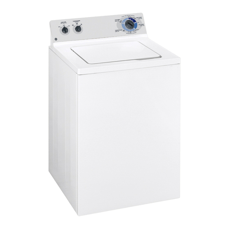
GE GTWS8455D0MC User manual

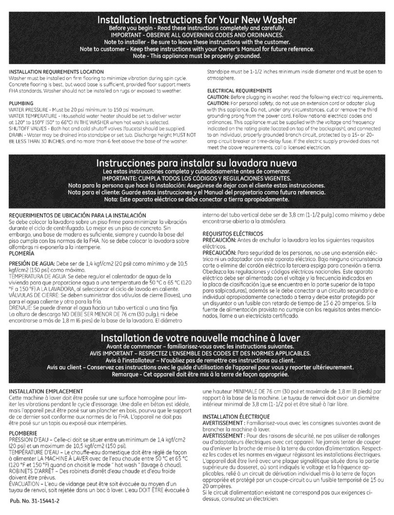
Installation Instructions for Your New Washer
Before you begin - Read these instructions completely and carefully.
IMPORTANT - OBSERVE ALL GOVERNING CODES AND ORDINANCES.
Note to installer - Be sure to leave these instructions with the customer.
Note to customer - Keep these instructions with your Owner's Manual for future reference.
Note -This appliance must be properly grounded.
_1 This is the safety alert symbol. This symbol alerts you to potential
hazards that can kill or hurt you and others. All safety messages will
follow the safety alert symbol and the word "DANGER","WARNING",or
"CAUTION". These words are defined as:
_ Indicates a hazardous situation which, if not avoided,
will result in death or serious injury.
_ Indicates a hazardous situation which, if not avoided,
could result in death or serious injury.
_ ndicates a hazardous situation which, if not avoided,
could result in minor or moderate injury.
INSTALLATIONREQUIREMENTSLOCATION
Washer must be installed onfirm flooring to minimize vibration during spin cycle.
Concrete flooring is best, but wood base issufficient, provided floor support meets
FHAstandards. Washer should not be installed on rugs. Donot install where
exposed to water or weather.
PLUMBING
WATERPRESSURE- Must be10 psi minimum to 125psimaximum.
WATERTElv]PERATURE- Household water heater should be set to deliverwater
at 120°to 150°F150°to 66°CIINTHEWASHERwhen hot wash isselected.
SHUTOFFVALVES- Both hot and cold shutoff valves (faucets)should besupplied.
DRAIN- Water may be drained into standpipe or set tub. Discharge height Iv]UST
NOTBELESSTHAN30 INCHES,and no more than 8 feet above the bose of the
washer. Standpipe must be 1-1/2 inches minimum inside diameter and must be
open to atmosphere.
Instrucciones para instalar su lavadora nueva
Lea estas instrucciones completa y cuidadosamente antes de comenzar.
IMPORTANTE: CUMPLA TODOS LOS CODIGOS Y REGULACIONES VIGENTES.
Nora para la persona que hace la instalaci6n: Aseg6rese de dejar con el cliente estas instrucciones.
Nota para el cliente: Guarde estas instrucciones y el Manual del propietario coma futura referencia.
Nota: Este aparato el_ctrico se debe conectar a tierra apropiadamente.
,_ Este es el sfmbolo de alerta de segufidad. El mismo alerta sobre
potenciales riesgos de muerte o lesiones tanto para usted con
para otras personas. Todos los mensajes de seguridad estar6n a
continuad6n del sfmbolo de alerta de seguridad y con la palabra
"PELIGRO',"ADVERTENCIA"o "PRECAUCION". Estas palabras se definen
coma:
_ ndica una situaci6n de riesgo que,si no se evita,
producir6 la muerte o lesiones graves.
_ Indica una situaci6n de riesgo que, si no se evita, podrfa
producir la muerte o lesiones graves.
_ ndica una situaci6n de fiesgo que, si no se evita, podrfa
resultar en lesiones menores o moderadas.
RE(.)UERIMIENTOSDEUBICACI6NPARALA INSTALACI6N
Sedebe colocarla lavadorasobre unpisofirme pare minimizerlavibraci6n durante
elciclo decentrifugado. Lomejor esun pisode concreto.Sinembargo,unabasede
madera essuficiente,siemprey cuando la basedel pisocumpla con lasnormas dela
FHA Nosedebe colocar la lavadora sobre alfombras niexponerla ala intemperie. La
lavadora nosedeber[ainstalar sobretapetes.No instalela mismaenlugaresdonde
pueda ester expuestaal ague olosfactoresclimciticos.
PLOMERJA
PRESIONDEAGUA- Debeser de 0,7kgf/cm 2(10psi)coma minimay de8,8 kgf/cm2
(125psi)coma maxima.
TEHPERATURADEAGUA- Sedebe regularelcalentador deaguede lavivienda par(]
queproporcioneague aunatemperature de50°Ca65°C(120°Fa 150°F)ALA
LAVADORA,al seleccionarel ciclode lavadoen caliente.
VALVULASDECIERRE- Sedeben suministrardos v6lvulasdecierre (llaves),una pare el
ague calientey otra par(] lafr[a.
DRENAJE- Sepuede drenarelague haciauntuba verticalo unatina fija. Laalturade
descargaNO DEBESERHENORDE76cm (30 pulg.),ni debe encontrarsea m(_sde 2,4
m(8 pies)dela basede lalavadora.
Eldiametro interno deltuba verticaldebeser de 3,8cm (1-1/2 pulg) coma minimay
debe encontrarseabierto ala atm6sfera.
Installation de votre nouvelle machine 6 laver
Avant de commencer - familiarisez-vous avec les instructions suivantes.
AVIS IMPORTANT - RESPECTEZ L'ENSEMBLE DES CODES ET DES NORMES APPLICABLES.
Avis 6I'installateur - N'oubliez pas de remettre ces instructions au client.
Avis au client - Conservez ces instructions avec le guide d'utilisation de I'appareil pour vous y reporter ult_rieurement.
Remarque - Cet appareil dolt 6tre mis 6 la terre de felon appropri_e.
,_ Ceci est un symbole d'alerte de s6curit& Cesymbole pr6vient d'un
risque mortel ou de blessures encouru par vous et d'autres personnes.
Tousles messages de s6curit6 s'inscriront 6 la suite du symbole
d'alerte et du mot <<DANGER>>,<<AVERTISSEMENT>>ou <<MISEEN
GARDE>>.Ces mats sont assod_s aux d6finitions suivantes:
Indique I1mminence d'une situation dangereuse qui,si elle
n'estpas 6vit6e, causera des blessuress6v_res,voire lamort.
_ Indique une situation dangereuse qui, sielle n'est pas
6vit6e,pourrait causer des blessures s6v_res,voire la mort.
1_111_11_ ndique une situation dangereuse qui, sielle n'estpas
6vit6e,pourrait causer des blessuresmineures ou
mod@6ment graves.
EMPLACEMENTD'INSTALLATION
Cettemachine 6 laverdolt 6trepos6esurune surface homog_nepour limiterles
vibrationspendant lecycled'essorage.Une dalleenb6ton est id6ale,mais I'appareil
peut6tre pos6surun plancherenbois,pourvu que lesupport de cedernier salt
conforme aux normes de construction.Uappareilnedolt pas6tre pos6surun tapis ou
expos6aux intemp6ries.Lalaveuse ne doit pas 6tre pos6e surdes tapis. Nepas la
poser aux endroits expos6s 6 I'eauou aux intemp@ies.
PLOMBERIE
PRESSIOND'EAU- Celle-cidolt se situerentre un minimum de0,7 kgf/cm2(10psi)et un
maximum de8,8kgf/cm2(125psi).
TEMPERATURED'EAU- Lechauffe-eau domestiquedolt @rer@gl@defagon 6alimenter
LAHACHINEA LAVERavecdeI'eauchaude entre50°Cet 65°C(120°Fet 150°F)quand
onchoisit le mode" hot wash "(lavage 6chaud).
ROBINETSD'ARRET- Desrobinetsd'arr_td'eau chaudeetd'eau froide doivent _tre
p,r@us.
EVACUATION- Ueaudevidange peut _tre soit@acu@eau moyend'un tuyau de renvoi,
soitrejet@edens unbac @laveEL'eauDOlTETRE@vacu@e6unehauteur MINIHALEDE
76cm (30po)et maximale de 2,4m (8pieds)par rapport 6 labasede la machine.
Letuyau de renvoidolt avoir undiam@treint@rieurminimal de3,8cm (1-1/2po)et_tre
situ@6 I'airlibre. Pub. No. 31-16702 09-12 GE

TOOLS YOU WILL NEED
Slip Joint Pliers Level
PARTSYOU WILL NEED
R S
2 Water Hoses
Part Number Accessory
plVil4X10002 - 4 ft_Rubber Hoses
Or
PMI4XIO005 - 4 ft_Braided Hoses
P Q
%oo
2 Rubber 2 Strainer Screens
Washers /Rubber Washers
Order on-line at GEApplianceParts.
cam or by phone at 800.626.2002.
Drain Hose - S ft
(attached to
washer back)
PARTSSUPPLIED
1 Cable Tie
Hose Guide Installation Instructions
guick Reference Guide
After the machine is in
the home, remove outside
packing material/carton from
washer.
Removebag (containing hose
guide B,Cabletie Dand full
Installation Instructions E)and
quick reference guide Jfrom
tub.
NOTE:Leavestyrofoam
shipping material Finsidetub
opening to hold tub in place
during the rest of installation.
Cuandola lavadora se
encuentre en su hogar,
deseche el material de
empaque sobrante de la
lavadora.
Retirela balsa(conla gufade
la manguera Byel ajuste del
cable Dylas Instrucciones
de Instalaci6n E)ygufa de
referencia r6pida J del envase.
NOTA:Dejeel material de
embalaje de gomaespuma
Fdentro del envase para
sostenerel mismo en su
lugar durante el resto de la
instalaci6n.
Lorsque la machine est 6
destination, enlevez I'ensemble
des mat6riaux ext6rieur et
cartons d'emballage.
Retirezle sac (contenant le
guide-tuyau B et I'attache
de c6ble D et lesinstructions
d'installation completes E)
guide de r_f_rence rapide J de
la cuve.
REMARQUE:laissezle mat#riel
d'emballage en styromousse
Fdans I'ouverture de la cuve
pour maintenir la cuve en
place pendant le reste de
I'installation.
Move washer closeto the final
position. Removestyrofoam
shipping material G.
Coloquela lavadora cerca del
lugar de instalaci6n definitivo.
Retireel material de embalaje
de gomaespuma G.
Positionnezla machine 6 laver
pras de sonemplacement
d6finitif. Retirezle mat6riel
d'emballage en styromousse G,
G
/

Pullthe drain hoseA out of the washer back.
Empujela manguera de drenaje A hacia afuera de la parte trasera de
la lavadora.
Sortez letuyau de vidange A de I'arri6rede la machine e laver. A\
C
Disconnect electrical cord N before installing water hoses. If not
installed,installrubber washer Pinone end ofhotwater hoseR.Thread
hot water hose Ronto connection labeled H at top rear of washer.
Handtighten and use pliers to tighten hoses between 1/8 and 1/4
turn beyond hand-tight.
If not installed,install rubber washer P in one end of cold water hose
S.Thread cold water hoseS onto connection labeled Cat top rear of
washer.Hand tighten and use pliers to tighten hoses between 1/8
and 1/4 turn beyond hand-tight.
Movewasher as close to final location as possible, leaving room for
you to make water,drain, and electrical connections to your home.
Antes de instalar las mangueras de agua, saque el cord6n el6ctrico
N de su lugar de almacenamiento. Si no esta presente, instale la
arandela de caucho Pen un extremode la manguera de agua caliente
R Enrosquelamanguera de agua caliente Renla piezapara conexi6n
con etiqueta Hen la parte posterior superior de la lavadora. Apri6tela
con la mano yluego gfrela un octavo de vuelta m6s con una pinza.
Ajustemanualmente yuseuna pinzapara ajustar lasmanguerasentre
1/8y1/4 de giro luego del ajuste manual.
Sino esta presente,instale laarandela de caucho Pen un extremo de
la manguera de agua frfa S.Enrosquela manguera de agua frfa Sen
la pieza para conexi6n con etiqueta Cen la parte posterior superior
de la lavadora.Ajuste manualmente yuse una pinza para ajustar las
mangueras entre 1/8 y1/4 de giro luego del ajuste manual.
Coloquela lavadora Iom6s cerca posiblea sulugar definitivo dejando
espacio para que se pueda drenar el agua ysepuedan efectuar las
conexiones electricas.
Retirezle cordond'alimentation (N)deson Iogementavant d'installerles
flexiblesd'alimentation d'eau.S'ilnest paspresent,installezunjoint en
caoutchouc (P)dansundes raccordsdu flexibled'eauchaude(R).Vissez
leflexible d'eauchaude (R)sur le raccord d'eau chaude (rep6re"H")qui
se trouve dans la partie sup6rieuredu dos de la machine.Serreze la
main,puisutilisezdespincespourserrerlesflexiblesde 1/8e 1/4detour
suppl6mentaire.
S'iln'est pas present,installezun joint en caoutchouc (P)dans un des
raccordsduflexibled'eaufroide(S).Vissezleflexibled'eaufroide(S)surle
raccordd'eau froide(rep6re"C")qui se trouve dansla partiesup6rieure
du dosdela machine.Serrezela main,puisutilisezdespincespourserrer
lesflexiblesde 1/8e 1/4 detour suppl6mentaire.
D6placezlamachinepour qu'ellesetrouve aussipr6squepossibledeson
emplacementd6finitif,tout envouslaissantassezdeplacepourraccorder
lesflexiblesd'alimentation d'eau,le renvoiet I'alimentation61ectrique.
N
P
P

C
Determinewhich isHOT
water line before attaching
water hosesto faucets.
Traditionally, HOTfaucet ison
left.
(Ifscreen washersare not
installed)With protruding part
of screentoward you, install
strainer screen/rubber washer
Q into each ofthe freeends of
two water hoses Rand S.
Connecthot water hoseRto
hot water outlet valve of your
home. Handtighten and use
pliersto tighten hosesbetween
1//4and 1/2 turn beyond hand-
tight. Open hot water valve.
Connectcoldwater hoseSto
coldwater outlet valveofyour
home.Handtighten and use
pliersto tighten hosesbetween
1//4and 1/2 turn beyond hand-
tight. Opencoldwater valve.
Checkfor leaksand dripsat
the hosecouplings.Tighten
asnecessary,
AverigOecu61esla tuberfa
de agua CALIENTEantesde
conectar losmanguerasde
agua alas Ilaves.Generalmente,
la Ilavede aguaCALIENTEse
encuentra a la izquierda.
(Silosflltros/arandelasde
caucho Q noestan presentes)
Conla porteconvexadelflltro
haciausted,coloqueelflltroy la
arandela de cauchoQ encoda
uno delosextremoslibresde los
manguerasde agua RyS.
Conectelamangueradeagua
calienteR a unav61vulade
salidadeaguacalienteensu
hogar.Ajustemanualmentey
useunapinzaparaajustarlos
manguerasentrei//4y i/2giro
luegodelajustemanual.Abrala
v61vuladeaguacaliente.
Conectelamangueradeagua
fifoS a unav61vuladesalida
deaguafrfaensuhogar.Ajuste
manualmentey useunapinza
para ajustarlosmangueras
entre 1/4y 1/2 giro luegodel
ajuste manual.Abrala v61vulade
agua fria.
Controlela presenciade p@rdidas
y goteosen losunionesde los
mangueras.AjustesegOnsea
necesario.
Rep@rezlerobinet d'eau
CHAUDEavant de raccorder
lesflexibles.Celui-ci setrouve
normalement 6 gauche.
(Silestamis/joints en
caoutchouc ne sont pas
presents)Avec lec6t@en
sailliedu tamis vers vous,
introduisez un ensemble
tamis/joint caoutchouc (Q)6
I'autre extr@mit@des flexibles
d'alimentation d'eau (R}et (S}.
Branchezle flexible d'eau
chaude (R)au robinet de sortie
d'eau chaude domestique.
Serrez6 la main, puis utilisez
des pinces pour serrer les
flexibles de 1/4 6 1/2 de tour
suppl@mentaire.Ouvrezle
robinet d'eau chaude.
Branchezle flexible d'eau froide
(S)au robinet de sortie d'eau
froide domestique. Serrez6 la
main, puisutilisez despinces
pour serrer lesflexiblesde 1/4
6 1/2 de tour suppl@mentaire.
Ouvrez lerobinet d'eau froide.
V@rifiezI'absencede fuite et
de suintement au niveaudes
raccords de tuyaux. Resserrez
si n@cessaire.

\\
\
Attach the U-shaped hose
guide B to the end of the
drain hose A. Placethe hose
in a laundry tub or standpipe
and secure it with the
cable tie D provided in the
enclosure package.
NOTE: Placing the drain hose
too far down the drain pipe
can cause a siphoning action.
No more than 7 inches of
hose should be in the drain
pipe. There must be an air
gap around the drain hose.
A snug fit can also cause a
siphoning action.
NOTE: The drain hose must
exceed 32" at some point
between washer back and
drain. If this height is not
obtained, the washer MAY
NOT operate properly.
NOTE:If longer drain hoseis
required,order drain hose
extension kit, GEpart number
WH49X301.Connectadditional
drain hose(contained in kit)to
original hosewith hoseclamp
(contained in kit).
Coloque la gu[a de la
tuber[a B en forma de U en
el extremo de la tuber[a de
desagOe A. Coloque la tuber[a
en una pila de lavar o tuber[a
vertical y suj@ela con la
brazadera de cable D que se
proporciona en el paquete
adjunto.
NOTA: Colocar la manguera
de drenaje muy debajo de
la tuber[a de drenaje puede
provocar un efecto de sif6n.
No debe haber mc_sde 7
pulgadas de manguera en
la tuber[a de drenaje. Debe
haber un espacio de aire
alrededor de la manguera
de drenaje. Sila manguera
estc_ muy ajustada, tambi6n
puede provocarse un efecto
de sif6n.
NOTA:La manguera de
drenaje debe superar las
32" en alg0n punto entre la
parte trasera de la lavadora
y el drenaje. Si no seobtiene
esta altura, es posible que
la lavadora NOfuncione de
forma correcta.
NOTA:Siserequiere una
manguera de drenuje mds
larga, mande a pedir el equipo
de extensi6n de la manguera
de drenaje, n0merade pieza
GEWH49X301.Conectela
manguera de drenaje adicianal
(incluidaen el equipa de
extensi6n)ala manguera
original usando la abrazadera
para la manguera (tambi_n
incluida en el equipo de
extensi6n).
Fixez le guide de bout de
tuyau Ben Uau bout du
tuyau de vidange A. Placez
les tuyaux dans une cuve
0 lessive ou la conduite
verticale et fixez-le avec les
attaches de cables Dfournies
dans I'emballage.
REMARQUE: Sivous mettez
le tuyau de vidange trop
bas, le tuyau d'6gout peut
causer un effet de siphon.
On ne peut pas mettre plus
que 17,8 cm (7 po) de tuyau
dans le tuyau d6gout. IIdolt y
avoir un espace d'air autour
du tuyau de vidange. Un
ajustement trop serr6 peut
6galement produire un effet
de siphon. Attache de cable
Attache de cable.
REMARQUE- La Iongueur du
flexible de vidange doit ¢tre
sup@ieuree 81,28cm 132po)
entre I'arriere de la machine
laver et le drain. IIest possible
que la machine _ laver NE
fonctionne PAScorrectement
sicette hauteur n'est pas
respect_e.
REMARQUE- Sila Iongueur du
tuyau d'@acuation ser@vele
insuffisante, commandez la
trousse de rallonge, node pi@ce
GEWH49×301. Branchezla
rallonge de tuyau d'@acuation
faisant partie de la trousseau
tuyau d'@acuation d'origine
I'aidedu collier pr@vu_ cette
fin.

[] WARNING
Electrical Shock Hazard
Plug into a grounded 3 prong outlet.
Do not remove ground prong.
Do not use an adapten
Do not use an extension cord.
Failure to follow these instructions can
result in death, fire, or electrical shock.
[] ADVERTENCIA
Riesgo de Descarga El_ctrica
Enchufe en un tomacorriente con conexi6n a tlerra
de 3cables
No elimine el cable de conexi6n aterra
No use un adaptador
No use un prolongador
Si no se siguen estos instrucdones se podr6 producir
amuer re, incer/dios o desca/gas el@ctricas
Circuit -Individual, properly polarized and
grounded 15 or 20 amp circuit breaker or
time-delay fuse.
Power Supply - 2 wire plusground, 120 Volt,
single phase,60 Hz,Alternating Current.
Outlet Receptacle - Properly grounded
3-prong receptacle to be located so the
power cord is accessiblewhen the washer is
inan installed position.Ifa 2-prong receptacle
is present, it is the owner's responsibility to
have 8 licensed electrician replace it with a
properly grounded 3-prong grounding type
receptacle.
Washer must be electrically grounded in
accordance with localcodes and ordinances,
or in the absence of local codes, in
accordance with the NATIONALELECTRICAL
CODE,ANSI/NFPANO.70 latest edition. Check
with a licensed electrician if you are not sure
that the washer isproperly grounded.
ATTACH GROUND
Circuito - individual, correctamente
polarizado y conectado a un disyuntor de 15
o 20 amperes o a unfusible con retardo.
Suministro de Corriente - 2 cable y
conexi6n atierra, 120 voltios,fase simple, 60
Hz.,CorrienteAlterna.
Receptaculo Externo - recept6culo de
3 clavUas correctamente conectado a
tierra, ubicado de modo que el cable
de corriente est_ accesible cuando la
lavadora est_ en una posici6n instalada.
Si hay un recept6culo de 2 clavUas, es
responsabilidad del propietario solicitar a
un electricista matriculado que reemplace
el mismo par un recept6culo de 3
clavijas con conexi6n a tierra, que est_
correctamente conectado a tierra.
La lavadora deber6 estar correctamente
conectada a tierra de acuerdo con los
c6digos y ordenanzas locales, o en
ausencia de c6digos locales, de acuerdo
con el CODIGONACIONALDEELECTRICIDAD
(NATIONALELECTRICALCODE),ANSI/NFPA
NO. 70, edici6n m6s reciente. En caso
de no estar seguro de que la lavadora
est_ correctamente conectada a tierra,
consulte a un electricista matriculado.
WIRE &GROUND
SCREW (OBTAIN
LOCALLY)
GROUNDINGINSTRUCTIONS
Thisappliancemustbegrounded.Inthe event
of malfunction or breakdown, grounding will
reduce the risk of electric shock by providing
apath of least resistance for electric current.
Thisappliance isequipped with a cord having
an equipment-grounding conductor and a
grounding plug. The plug must be plugged
into an appropriate outlet that is properly
installed and grounded in accordance with
all local codes and ordinances.
[]WARNING - Improper connection of
equipment-grounding conductor canresultin
ariskofelectric shock. Checkwith aqualified
electrician or serviceman if you are in doubt
as to whether the appliance is properly
grounded.
Do not modify the plug provided with the
appliance - if it will not fit the outlet, have
a proper outlet installed by a qualified
electrician.
If required by local codes, an external 18
gauge or larger copper ground wire (not
provided) may be added. Attach to washer
cabinet with a#8-18 x ½" sheetmetal screw
(available at any hardware store)to rear of
washer asillustrated.
INSTRUCCIONESPARAPUESTAA TIERRA
Estaunidaddebetenerunaconexti6nparapuesta
atierraadecuada,yaquesiseaveriaonofunciona
correctamentelapuestaatierrareducirdetriesgo
de electrocuci6nal proveeruna ruta de menor
resistenciapara tacorrienteet@ctrica.Launidad
est6equipadaconun cablequeposeetantoun
conductorcomaunenchufeparapuestaa tierra.
Etenchufesedebeenchufarenuntomacorriente
appropiado que est@correctamente instatado
yconectadoa tierrasegQntoestiputadoen los
c6digosyreglamentoslocales.
[] ADVERTENCIA -Unconductorparapuesta
atierramalconectadopuedecrearunriesgode
electrocuci6n.Consultecon un electricistaoun
t_cnicocalificadosi tienealguna dudasabrela
puestaatierraapropiadadetaunidad.
No modifiqueel enchufeque se proveecon la
unidad - si#ste no entra en el tomacorriente,
contrate a un etectricistacalificado para que
instateuntomacorrienteapropiado.
Si los c6digos locales Io requieren,se podr@
agregarun cable a tierra externode cobrede
calibre18o mdsgrande(noprovisto).Adhieraet
gabinetedela lavadoraconuntornittodechapa
metalicaN°8-18x 1/2" (disponibleen cualquier
tienda de repuestos)a ta parte trasera de ta
lavadora,siguiendolaitustraci6n.
[] AVERTISSEMENT
Risque d'_lectrocution
Broncher I'opporeil dons une p/ise 6 3broches mise
6 la terre
Ne pas enlever la broche de raise 6 la terre
Ne pas uflliser un adaptateur
Ne pas uflliser un cordon de railonge
L'omission d'observer ces directives peut ent/_ner
la mort, I'incendie ou I'@lect/Dcution
Circuit - Individuel, correctement polaris@
et mis 6 la terre, disjoncteur ou fusible
temporis@de 15 ou 20 amp@es.
Alimentation _lectrique - 2 ills plus la mise
6 la terre, 120 volts, monophas@,60 Hz,
courant alternatif.
Prise _lectrique Prise 6 3 voles
correctement mise6 la terre situ@edefa_on
6 ce que le cordon salt accessible Iorsque
la laveuse est install@edans sa position
d@finitive.Si la prise n'est qu'6 2 voles, il
est de la responsabilit@ du propri@aire
de demander 6 un @lectricien agr@@
de la remplacer par une prise 6 3 voles
correctement mise6 la terre.
La laveuse dolt @trecorrectement mise 6
la terre conform@ment aux codes Iocaux
de I'@lectricit@,ou en I'absence de codes
Iocaux, conform@ment6 la derni@e @dition
du NATIONALELECTRICALCODE,ANS!/NFPA
NO. 70. Demandez 6 un @lectricienagr@@
de v@ifier la connexion si vous n'@tespas
certain que la laveuse est correctement
mise 6 laterre.
INSTRUCTIONSDE MISEA LA TERRE
Cetappareildoltetremis6 laterre.Encosde
mauvaisfonctionnementoudepanne,la mise
(_laterrer@duitlerisquedechoc@lectriqueen
fournissantunpassagedemoindrer@sistance
aucourant@tectrique.Cetappareitest@quip@
d'uncordond'atimentationavecunconducteur
demise6 la terreet unefichedeterra II faut
brancherla fiche dans une priseappropri@e,
instaii@eet mise6taterreconform@mentaux
codeset r@giementstocaux.
[] ATTENTION - Lemauvaisbranchement
duconducteurdemise6 la terrepeutcauser
desrisquesdechoc@lectrique.Encasdedoute
surtamise6taterredet'appareit,consulterun
@tectricienagr@eouuntechniciender@paration.
Nepasmodifierlafichefournieavect'appareit.
Silafichene correspond pas6 laprise, faire
installerunepriseappropri@eparun@tectricien
qualifi@.
Sites codes tocauxt'exigent, un fit de terre
ext@ieurencuivredecalibre18ousup@ieur
(nonfourni)peut@treajout@.Fixer(_t'enceinte
dela taveuse6 t'aided'unevis(_t6te#8-18xtA
po(danstoutebonnequincaitterie)(_t'arri@ede
tataveuse,commeittustr@.
W
Makesurelarqedialcontrolon
washerispushedintotheOFF
position.
Insertplugofelectricalcord
intoa IISV,15-or 20-ampwall
receptacle.Movewasherinto_
finalposition.PlacelevelVonfiat
topsideedgeandsideofwasher..
AdjustallfourlevelinglegsWuntil
washerislevelleft-to-riqht and
front-to-back RemovelevelV.
Opentub lid.Removeanddiscard
tubshippingmaterialF(seeStepZ).
Removeplasticprotectorsheet
romcontrolpanelface.
Aseq0resedequelaperillade
controlde lalavadoraseencuentra
presionado,en laposici6nde
apagado(OFF).
Enchufeelcord6nelectricoenun
t0macorrientede115voltiosy
de15620amperios.Desplacela
lavadorahaciasuposici6nfinal.
Coloq.ueelnivelVene extremo
supenorlateralyenel.lateral
delalavadora.Ajustelascuatro.
patasniveladorasWhastaquela
lavadoraesteniveladadeizquierda
aderechay delfrentea laparte
trasera.QuiteelnivelV.
Abralatapadeltambor.Quitetina
materialevioF(consulteelpaso1).
Quitelalaminaprotectorade
plasticpdelfrentedeltablerode
control.
V@ifiezquele9randbouto,nde
commanaeaela macnlnea
laversetrouveenposition"OFF
"(arr¢t).
Branchezlaficheducordon
d'alimentationdans,uneprise
murale,ae :].IS,y,lS,/,20am,peres.
vlacezlamachinea lavera son
emplacementdefinitif.Placez
unn_veauVsurlebordlateral
_aUperie,ur6 platetsurle,c6!ede
m,acnlnea ,aver.njus_ezles
,qua_rep,,attesae,mise(_,nivea,u
yvjusqu',acequelamacnlne,a
Lav,ersol_aunlveguaega,ucne
a arol_ee_a'avan_enarrlere.
Enlevezleniveau(V).
Ouvrezlecouvercledutambour.
D@oseretmettreau rebut,'a
remousma_erlauxa'expeamonF
(voirI'_tape1).
En[evezlafeu,illedeplastiq,ue
qulrecouvrelepanneauae
commanae.
SPECIALINSTALLATIONREQUIREMENTS,
ALCOVEORCLOSETINSTALLATION
•If your washer isapproved for installation
in an alcove or closet, there will be a label
on the back of the machine describing
requirements.
•Minimum clearance between washer and
adjacent walls or other surfaces:0" either
side,2"front, 3" rear,24"top..
• Closetdoorsmust be Iouveredorotherwise
ventilated and have at least 60 square
inches of open area for washer only,
or if the closet contains both a washer
and a dryer, door must contain at least
120 square inches of open area equally
distributed.
NOTE:The clearances stated on this label
are minimums. Consideration must be
givento providing adequate clearances for
installing and servicing.
MOBILEHOMEINSTALLATION
• Installation must conform to STANDARD
FOR MOBILE HOMES,ANSI Al19.1 and
NATIONALMOBILEHOMECONSTRUCTION
&SAFETYSTANDARDSACTOF1978(PL93-
383).
REQUERIMIENTOSPARAINSTALACION
ESPECIALENUN NICHOO ARMARIO
• Sila lavadora ha sido aprobada para
serinstalada en un nicho o armario,
debe haber una etiqueta en la parte
posterior de la mc_quinaque describa los
requisitos.
• Distancia minima entre la lavadora y las
paredesadyacentes o cualquier otra
superficie: 0 cm (0pulg.)a loslados, 5 cm
(2pulg.)al frente y 7,6cm (3pulg.)arrows.
• Laspuertas de losarmarios deben tener
persianas o ventilaci6n y un @ea abierta
de por Iomenos 387 cm2(60pulg.2)si
seinstala s61ola lavadora; sinembargo,
sien el armario seha de colocar una
lavadora y una secadora, laspuertas
deben tener un @ea abierta igualmente
distribuida de por Iomenos 774 cm2(120
pulg._).
NOTA:Losespaciosmencionados en las
etiquetas son losm[nimos. Sedebe dar
una gran importancia al suministro de un
espacio adecuado para la instalaci6ny el
mantenimiento de losaparatos.
INSTALACIONENCASASMOVILES
• Lainstalaci6n debe conformarse a la
norma ANSIAl19.1 para casas m6viles
y a la Leynacional de normas para
la construcci6n y seguridad de casas
m6vilesde 1974 (PL93-383)(National
Mobile Home Construction & Safety
Standards Act of 1974).
INSTALLATIONDANSUN RleDUITOU UN
PLACARD
• Sion recommande I'installation de votre
machine 0 laver dans un r6duit ou un
placard, vous trouverez lesnormes
d'installation correspondantes sur une
6tiquette au dos de la machine.
• D@gagementminimal entre la machine
et lessurfaces mitoyennes :0 cm (0 po)
de part et d'autre, 5 cm (2po)(3I'avant et
7,6cm (3 po)(]I'arri@e.
• Lesportes de placard doivent @tre
surbaiss6es ou autrement ventil6es
pour assurer une surface de ventilation
minimale et uniform6ment distribu6e
de 387 cm2(60po2)dans le cas d'une
machine (]laver seuleou de 77Acm2(120
po2)dans le cas d'un ensemble machine
(_laver/s@che-linge(s6cheuse).
REMARQUE- Lesjeux indiqu6s sur cette
amche constituent desjeux minimaux.
IIconvient 6galement de pr6voir un
d6gagement sumsant pour lesop@ations
d'installation et d'entretien.
INSTALLATION DANS UNE MAISON
MOBILE
• L'installation dolt @re conforme 6 la
norme ANSI Al19-1 intitul@ <<STANDARD
FORMOBILE HOMES>>et 0 celle
intitul@ <<NATIONALMOBILE HOME
CONSTRUCTION & SAFETYSTANDARDS
ACT OF 1974>>(PL93-383).

Congratulations! Your installation is complete. Referto your Owner's Manual for operation instructions.
iFelicitaciones! Ustedacaba de terminar suinstalaci6n. Paraconocer las instruccionesde operaci6n consulte el Manual del propietario.
F_licitations ! L'installation est termin6e. Reportez-vousau guide d'utilisation pour connaTtrele mode d'emploi de la machine.
Check for leaks after you turn on the washer, one
month later, and every 3 to 6 months.
GEstrongly recommends the use of new water
supply hoses. Hoses degrade over time and need to
be replaced every 5 years to reduce the risk of hose
failures and water damage.
Controle que no haya goteras luego de encender la
lavadora, un mes despu6s, ycada 3 o 6 meses.
GE recomienda enf6ticamente el uso de mangueras
nuevas de suministro de agua. Las mangueras se
desgastan con el tiempo ydeben reemplazarse
carla 5 aBos para reducir el riesgo de fallas en las
mangueras ydaBos provocados por el agua.
Un mois apr_s et tousles 3 6 6 mois, v@ifiez s'il ya des
fuites apr_s avoir mis la machine 6 laver en marche.
GEvous recommande fortement d'utiliser des tuyaux
d'alimentation en eau neuf. Les tuyaux se d6gradent
avec le temps et doivent @tre remplac6s tousles 5 ans
pour r6duire le risque de rupture des tuyaux et/ou de
d6gats des eaux.
For Questions on Installation, Call 1-800-626-2003 (U.S.) Si tiene alguna pregunta en cuanto a Ia instalaci6n, Pour toute question au sujet de I'installation, veuillez
1-800-561-3344 (Canada) llame al1-800-626-2003 (enlos EE.UU.) composer le1-800-626-2003 (letats-UnJs)
1-800-561-3344 (en Canad6) 1-800-561-3344 (au Canada)
This manual suits for next models
16
Table of contents
Other GE Washer manuals

GE
GE WBVH Installation guide

GE
GE MODEL WA7800R User manual

GE
GE GTWN5450DWW User manual

GE
GE WWA8355V User manual

GE
GE WSLS11002 Original instructions

GE
GE GTWN8250DWS User manual

GE
GE GTWS8455DMC Assembly instructions

GE
GE Profile WPRB8050 User manual

GE
GE Profile WPDH8850 Original instructions

GE
GE LAVEUSES WBVH5200 Original instructions

GE
GE GTW680 series Original instructions

GE
GE Profile WPGT9350 Operating instructions

GE
GE Profile PTW7O5 Original instructions

GE
GE Profile Harmony WPGT9360 Operating instructions

GE
GE WCCB1030D1WC Warranty User manual

GE
GE WWA7619M User manual

GE
GE WWA5710R User manual

GE
GE G005 User manual

GE
GE G016 User manual

GE
GE GTWN5050MWS Manual