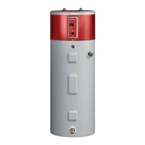
UsingtheEnerggMenu.
TheEnergyMenuisalsousedtochangethewaterheater
operatingmodes,to convertthetemperaturedisplayfrom
°Fto %,orto viewtheFAgs.Thereisalsoa Diagnostic
Menuthat isonlyaccessibleto a certifiedservice
technicianor plumberintheeventserviceisneeded.
Operating Modes
UsethisoptiontochangebetweeneHeatTM, Hybrid,
StandardElectricand HighDemandmodes(described
onpage8).
r_To accessany of these modes, pressthe ENERGY
MENUbutton and then pressENTER.
_] elect Operating Modes on the menu listand
pressENTER.
r_ Selectthe desiredoperating mode by using the UPor
DOWNarrow buttons and then pressing ENTERagain.
[_-] To cancel and return to the main Energy Menu, press
the LEFTarrow button.
r_To getmoreinformationoneachmode,whilethe
modeishighlighted,presstheRIGHTarrowbutton
to reada description.
B-] UsetheUPor DOWNarrowbuttonstoscrollthrough
thedescriptionscreens.
E]Use theLEFTarrowbuttonto returnto theOperating
Nodemenulist.
°Fand °CConversion
Thewatertemperaturedisplaywilldefaultto °F.Toshow
thetemperaturesin °C,presstheENERGYMENUbutton;
thenpressENTER.Thesesettingswillberemembered
andreturnedfollowinga poweroutage.
r_-] PresstheDOWNarrowbuttontogoto "Choose°F
and°C"and pressENTER.
o o
PressENTERto changefrom Fto C.Themainscreen
o
willthenbeshownwiththetemperaturein C.
r_To cancelandreturntothemainEnergyMenu,press
theLEFTarrowbutton.
NOTE:Tochangebackto°F,repeatSteps1and 2.
Frequently Asked Questions
Thismenuitemanswersbasicquestionson coldair,
thefilter,operatingmodesandnoise.Allofthisinformation
iscoveredinthisUseandCaremanual.Ifthismanualis
misplaced,youcanrefertothissectionfor answers.
r_-]Toaccessthe FAQs,presstheENERGYMENUbutton
andthenpressENTER.
_] PresstheDOWNarrowpadtogoto "FAQs"andthen
pressENTER.
Therearefourquestioncategories:
ColdAir:
Q:Whyistherecoldair?
A:Hybrid,eHeatTM andHighDemandmodessaveenergy
by usingheatfromtheairto heatthewaterandthereby
coolingthesurroundingair.Thisgivessizableenergy
savings.
Q:Howto stopcoldair?
A:PresstheSTOPCOLDAIRbuttononthekeypad.This
reducestheefficiencyofthe heater.Unitwillchange
backto previousmodeafternumberof daysselected.
Filter:
Q:Whyisthereafilter?
A:InHybridandeHeatTM theunitmovesairthroughthe
system.Thefilterprotectsthe unitfromdirt.Acleanair
filter improvesefficiency.
Q:Howto cleanthefilter?
A:Leavepoweronandremovefilterfromtopofunit.Filter
canbewipedcleanor rinsedwithwarmwater.Adirty
filterwillreducewaterheaterefficienc!!
Modes:
Q:WhatisHighDemand?
A:HighDemandcanbeusedwhenhotwater usageis
higherthannormal.Theunitwillbelessefficientbutwill
heatwaterfasterinresponseto longwaterdraws.Forall
normaldraws,theunitwillstilluseefficienteHeatTM.
Q:WhatisStopColdAir?
A:Thismodewillstopcoldairtemporarilybutreduces
theefficiencyoftheheater.Theunitwillchangeback
to thepreviousmodeafterthenumberofdaysselected.
Q:WhatisVacationOrAway?
A:Ifyouaregoneforanextendedperiod,thismode
lowersthewatertemperaturetoreduceenergyused.
Unitwillswitchtothepreviousmodeonedaybefore
yougetback.
Q:WhatiseHeatZM?
A:eHeatTM isthemost-efficientmode.Ittakesheatfrom
theairto heatwater,therebycoolingthesurroundingair.
Slowerrecoverybutmost-efficientmode.
Q:WhatisHybrid?
A:TheHybridmodecombinesbenefitsofeHeatTM withthe
speedandpowerof StandardElectric.Thisprovidesgreat
performancewithlessenergy.(Recommendedmode.)
Q:WhatisStandardElectric?
A:StandardElectricmodeusesonlytheresistanceheaters
to heatthewater.Thisgivesfasterhotwaterrecovery
than Hybridmode,butusesmoreenergy.
Noise:
Q:Whyistheunitnoisy?
A:Inthemostenergy-efficientmodes,eHeat TM, Hybrid
andHighDemand,themethodusedto heatthewater
generatessomenoise.Someamountoffan noiseis
normal.
I_1 Usethe UPorDOWNarrowbuttonsto selectthe
categorythat pertainsto yourquestionand press
ENTER.
I_-I TocancelandreturntothemainEnergyMenu,press
theLEFTarrowbutton.
I_1 Oncethecategoryisselected,usethe UPor DOWN
arrowbuttonstoselectthedesiredquestionsand
pressENTER.
B-] Usethe UPorDOWNarrowbuttonsto readthrough
theinformationscreens.
E] Whendone,presstheLEFTarrowbuttontoreturn
totheFAQsmenu.
10
