Gearmore T230 Guide

ROTARY
TILLER
"T" SERIES
Starting with Serial No:
Operation, Service
& Parts Manual
February 2016
Form: T355Tiller/T355Tiller_08-17

TABLE OF CONTENTS
SECTION DESCRIPTION ................................................ PAGE
GENERAL INFORMATION
Application ........................................................................................... 1
Symbols ................................................................................................. 1
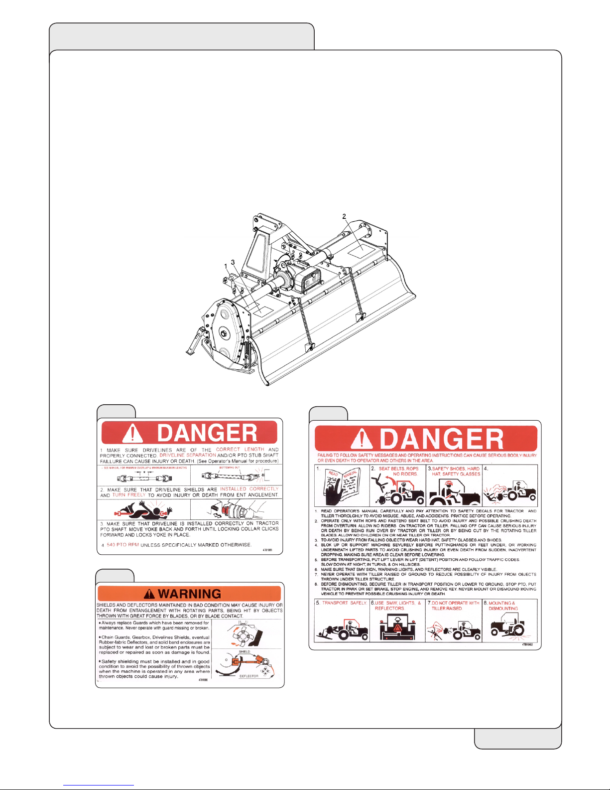
Safety labels .......................................................................................... 2
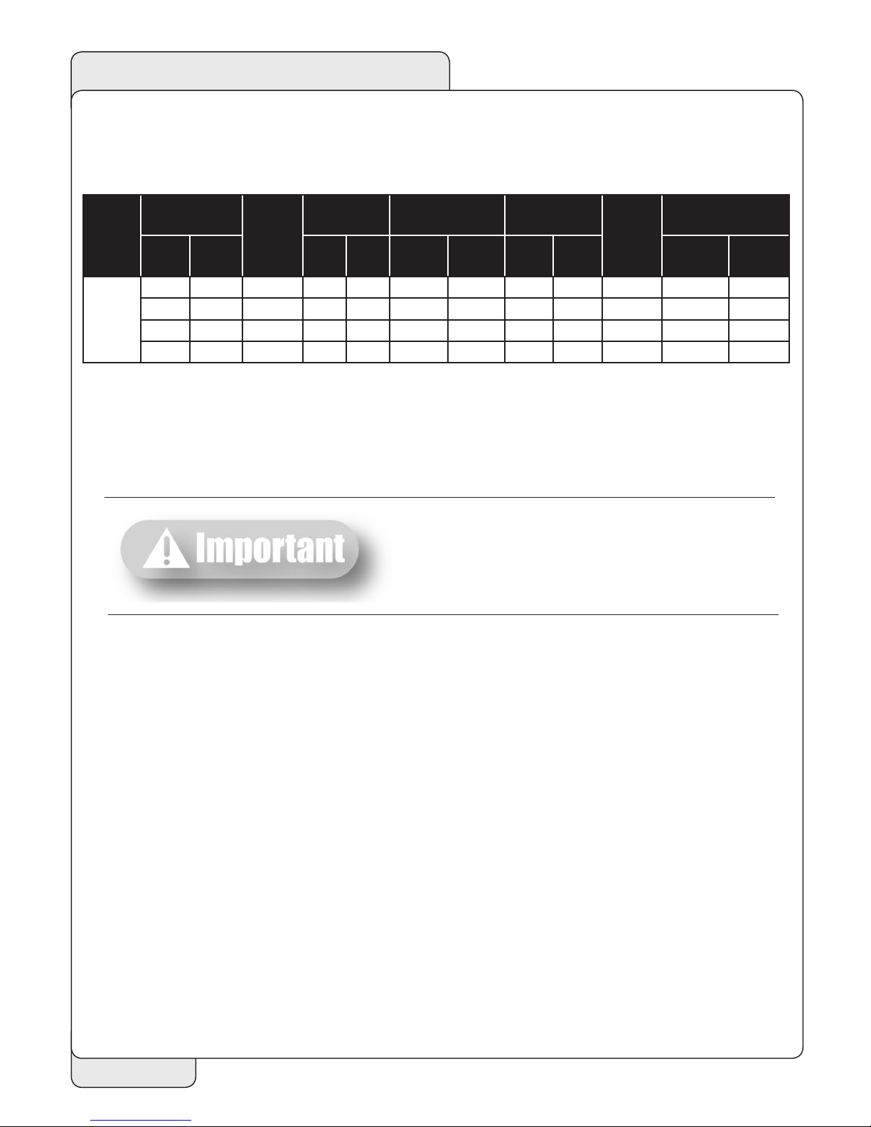
Technical data....................................................................................... 3
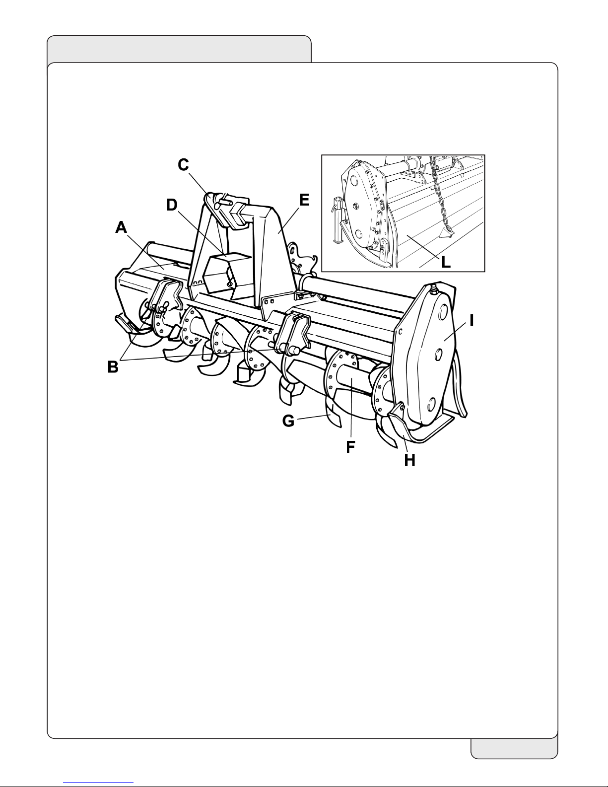
Main parts terminology ...................................................................... 4
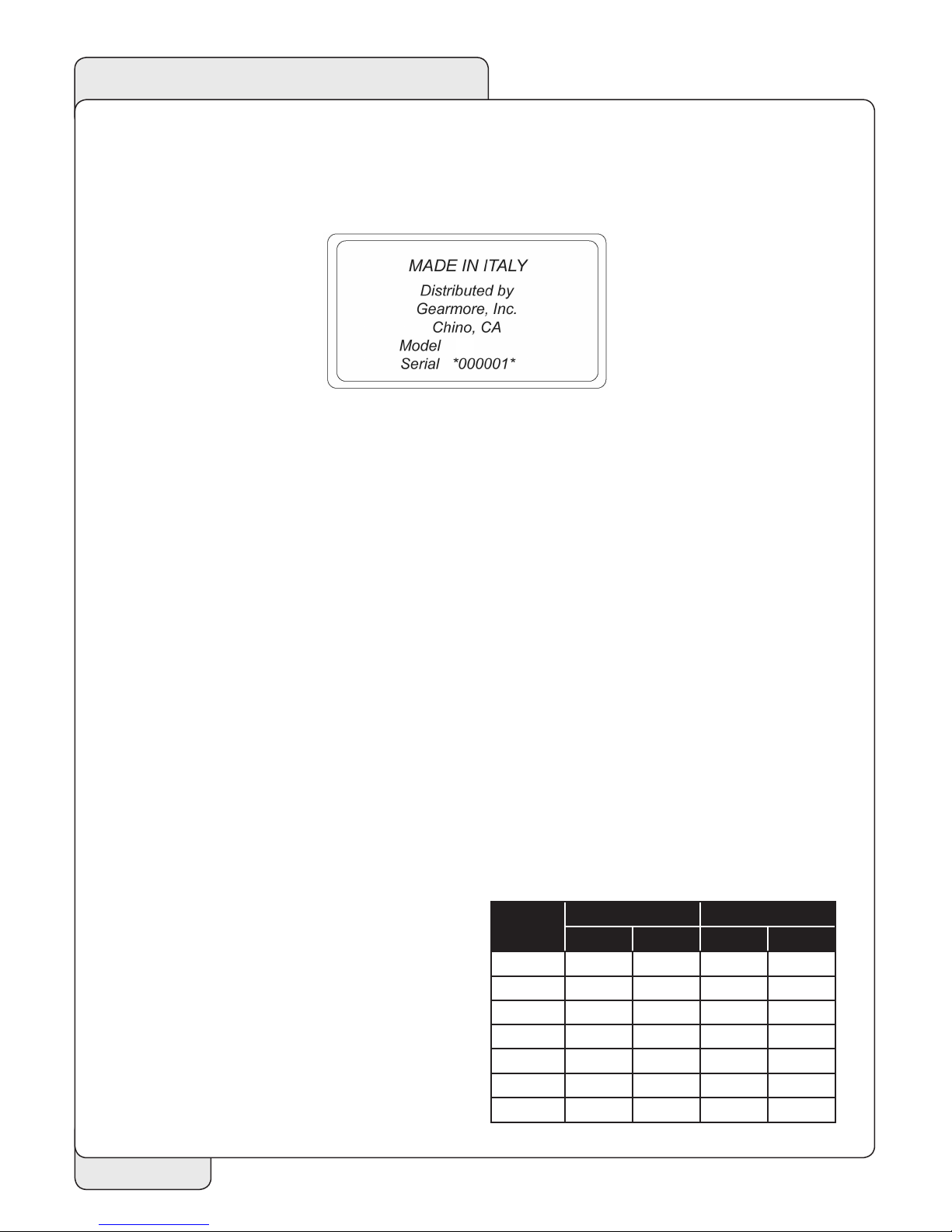
Identication plate............................................................................... 5
Recommended use .............................................................................. 5
Inappropriate use................................................................................. 5
Torque Specication............................................................................ 5
SAFETY
Safety in the workplace ....................................................................... 6
User's requirements............................................................................. 6
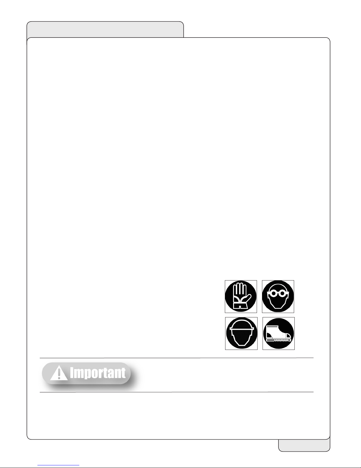
Work clothing....................................................................................... 6
General safety norms .......................................................................... 6
Preparation ........................................................................................... 7
SET UP
Attachment to the tractor................................................................... 8
PTO shaft connection ....................................................................... 11
Slip clutch drive shaft......................................................................... 11
Working depth adjustment............................................................... 12
Leveling board adjustment............................................................... 13
MAINTENANCE
Road transport ................................................................................... 14
Shut down........................................................................................... 14
First check........................................................................................... 14
Every 8 working hours...................................................................... 15
Every 20 working hours ................................................................... 15
Every 50 working hours ................................................................... 15
Every 500 working hours ................................................................. 15
Replacing clutch linings .................................................................... 16
SPARE PARTS
How to order spare parts ................................................................. 17
Troubleshooting chart....................................................................... 18
Tiller Assembly T230, T280 & T305.............................................. 19
Drive Assembly.................................................................................. 21
Gearbox Assembly ............................................................................ 23
Rotorshaft Assembly......................................................................... 25
Rotorshaft ........................................................................................... 27
Main Deck Assembly ........................................................................ 29
Tailboard Assembly............................................................................ 31
Tiller Assembly T355......................................................................... 33
Gearbox Assembly T355................................................................... 37
Driveshaft EYE81074-2255............................................................339
Driveshaft YE01074-13747 .............................................................. 40
Slip Clutch Assembly ......................................................................... 41
OPTIONS
Rear Roller ........................................................................................... 42
Cutting Disc......................................................................................... 43
LIMITED WARRANTY .................................................................................................. 44

INTRODUCTION
No part of this manual shall be reproduced, copied or disseminated by any means, without
manufacturer prior authorization in writing.
Gearmore reserves the right to make any necessary changes without giving prior notice, in
order to optimize the quality and safety features and does not commit itself to updating this
manual every time a change is made.
This booklet provides a thorough and accurate description of the instruction and maintenance
activities to be carried out on the tiller you purchased. We congratulate you on your choice and
urge you to thoroughly familiarize yourself with and follow the instructions contained in this
manual. This will assure you a long, safe and trouble free working life for your tiller.
Gearmore shall not assume any responsibility should problems arise as a result of lack
of compliance with the instructions and/or operator's negligence.
The manual is divided in chapters and paragraphs and the pages are numbered, thus offering
accurate and precise information.

1
GENERAL INFORMATION
GENERAL INFORMATION
APPLICATION
The T Series Rotary Tillers are designed to till soil for seedbed or planting preparation.
The T Series Tillers are adapted for tractors with 540 and 1000 rpm PTO speeds and
Category 2, 3-point hitch tractors up to 160 HP.
SYMBOLS
This booklet contains three "safety pictograms" which highlight the relevant danger
levels or important information:
It draws the operator's attention to special situations
which may jeopardize people's safety.
It draws the attention to situations which unfavorably
affect the machine efciency, but not people's safety.
It is used for general information, when people's safety
or the efciency of the parts are not at risk.

2
GENERAL INFORMATION
SAFETY LABELS
The safety labels and information on the machine (labels 1, 2 and 3), must be
complied with. Failure to comply with these warnings may result in severe injuries
or even death. Make sure that the labels are always present and legible; should
this not be the case, contact your nearest Gearmore dealer to request replacements.
12
3

3
GENERAL INFORMATION
TECHNICAL DATA
When asking for information or technical service,
always specify the machine type and width.
Model
Tilling
Width HP
Weight
(Approx.)
Working Depth
(Max.)
Side
Drive Blades
(Qty.)
Blades
cm inches kg lbs. cm Inches Chain Gear Blades/
Flange
Shape
T
230 90 90-100 930 2140 25 10 * 60 6 Curved
280 110 100-120 1110 2205 25 10 * 66 6 Curved
305 120 120-160 1150 2275 25 10 * 72 6 Curved
355 140 120-160 1250 2415 25 10 * 84 6 Curved

4
GENERAL INFORMATION
MAIN PARTS TERMINOLOGY
A) Frame
B) Lower 3-point hitches
C) Upper 3-point hitch
D) Cardan guard
E) 3-point mast
F) Rotor
G) Tines
H) Side skids
I) Transmission case
L) Cover

5
GENERAL INFORMATION
IDENTIFICATION PLATE
An identication plate is placed on each tiller and is structured as follows:
Serial number (sample):
RECOMMENDED USE
The tillers described in this instruction and maintenance manual, have been designed explicitly
to till the land. Any other use jeopardizes the operator's safety and the machine integrity.
INAPPROPRIATE USE
The tillers shall not be used as follows:
•Connected to vehicles which do not have a suitable power or weight.
•Without being properly installed by securing the hitch brackets to all three points
of the tractor lift unit.
•Tilling of extremely stony or unsuitable ground.
•Raising or lifting of the equipment when the power take off is engaged.
•In close proximity to person/s when power is engaged.
•Do not stand or step on the equipment when it is being operated or transported.
• Do not operate the machinery while wearing unsuitable (loose tting) clothing.
TORQUE SPECIFICATIONS
For correct hardware tightening on the tiller,
we suggest the use of suitable torque wrench
and the applicable torque as listed in the table.
T
Thread 8.8 10.9
Nm Lb-ft Nm Lb-ft
M6 11 8.5 17 12
M8 28 20 40 30
M10 55 40 80 60
M12 95 70 140 105
M14 150 110 225 165
M16 240 175 305 225
M18 330 250 475 350

6
SAFETY
SAFETY IN THE WORKPLACE
Most of the accidents, which occur while the operator is using the machine or the equipment or
carrying out maintenance and repair activities, are caused by the non-compliance with the main
safety requirements. Therefore the potential risks must be fully understood and special attention
must be paid to the activity which is being executed.
If potentially dangerous situations are known,
accidents can be prevented!
USER'S REQUIREMENTS
The equipment user must have the following:
Physical: good sight, co-ordination and capability to execute all instructions in a safe manner.
Mental: the users must understand and follow the prescribed norms, rules and safety measures.
They must be careful, pay attention to their own safety and the safety of other people and act
properly and in a responsible way.
Training: the users must read and understand this manual, its pictures and charts, and the
identication and hazard plates. They must be specialized, trained and qualied on any use
and maintenance activities.
WORK CLOTHING
The following clothing and personal protective equipment must be used when working and
executing maintenance and repair activities:
• Overalls or any other comfortable outt; make sure that
they are not too loose since they might be caught by
moving parts.
•Protective gloves.
•Goggles or mask to protect the eyes and face.
•Safety helmet.
•Safety shoes.
Wear only personal safety accessories in good
condition and complying with the rules in force.
GENERAL SAFETY NORMS
The features of the area where work is taking place must always be taken into consideration:
•Do not stand in the working radius of the operating machinery or any other machine
accessories when the equipment is running.

7
SAFETY
PREPARATION
Preparing For Work:
•Do not drink alcohol, take drugs, or any other substances which may affect your
ability to use the equipment before or when working.
• Make sure that there is sufcient fuel in the tractor to prevent the machine from
stopping during work.
•Do not use the equipment under unsafe conditions, e.g. do not make temporary repairs
just to start or keep working; do not work at night if the area is not well illuminated.
When working or executing maintenance activities, remember:
•The labels and stickers providing instructions on the use of the equipment or
information on dangers must not be removed or hidden, and must be legible.
•Do not remove the safety devices, covers and safety guards, unless maintenance
activities are being carried out. If the safety devices must be removed, turn the engine
off, remove them correctly and re-install them before turning the tractor on.
•Do not lubricate, clean or adjust moving parts.
•Use the appropriate tools to execute maintenance or adjustment activities on the
equipment.
•Do not use damaged or unsuitable tools, e.g. pliers rather than wrenches etc.
•Prior to carrying out activities on hydraulic lines under pressure, or disconnecting their
components, make sure that the line is no longer under pressure and that it does not
contain any hot uids.
• Check all the ttings and make sure that they are well connected before supplying
pressure to the hydraulic lines.
•Make sure that no tools, clothes or any other materials are left in areas where moving
parts are present when the maintenance and repair activities are completed.
•Do not give directions and make signals at the same time during a maneuver.
Maneuver directions and signals must be given from one person only.
•Do not unexpectedly call an operator, if not necessary. Do not startle the operator, e.g.
by throwing objects.
• Pay attention to people in the vicinity of the work area, especially children!
•Make sure that nobody is standing in the working range of the equipment.
•Do not use the equipment to lift people.
• When the equipment is not needed, turn the engine off, leave the vehicle on a at sur-
face, with the rst gear and the parking brake engaged. Disengage the power take off.
•Do not execute any cleaning, lubrication, repair or adjustments when the engine is
running and the equipment is in the raised position.
•Do not work on steep slopes, if the stability of the vehicle can be jeopardized.
Manufacturer shall not assume any responsibilities if these instructions are not
strictly followed.

8
SET-UP
ATTACHMENT TO THE TRACTOR
This tiller may be attached to any tractor equipped with a Cat. 2, 3-point hitch with suitable
ball ends. Before attaching the equipment to the tractor, set both on at and smooth ground
and make sure that nobody is standing beween them.
3-POINT CATEGORY 2 HITCH
To connect the tiller to the tractor's Cat. 2, 3-point hitch, do the followng operations:
1) Put the oating brackets in the lower
position inserting the pin A in the upper
hole as shown in (picture 1); this gives
you the standard A.S.A.E. vertical
dimension of 20" (picture 2). The
horizontal distance between the
brackets is 32 ½".
Picture 2
Picture 1

9
SET-UP
2) Remove the cotter pins from the
hitch pins (picture 3);
3) Remove the lower hitch pins from
the lower hitch blocks
(picture 3);
4) Before attaching the equipment to the tractor, make sure that the ground is smooth
and at and that nobody is standing between the tractor and the tiller; slowly move
the tractor towards the tiller by aligning the tractor lifter arms with the blocks' holes
(picture 4); turn the engine off and pull the brake;
Picture 4
Picture 3

10
SET-UP
5) Insert the lower hitch pins through the
hitch blocks and ball ends (picture 5);
6) Secure them by means of the cotter
pins which were previously removed
(picture 5);
7) Connect the tractor top link to the third upper point by removing the pin located
between the two plates, inserting the top link and securing it by means of the cotter
pin. Shift the parking stand in the upper position .
8) Adjust the top link so that the upper part of the frame is parallel to the ground. Block
all the linking parts by means of the sway chains or arms.
9) Make sure that the central unit axis (case/bevel gear pair) is parallel to the ground,
thus minimizing the stresses on the power take off and increasing the working life of
the equipment.
After executing all the above mentioned activities,
make sure that all the nuts and bolts are tightened.
Picture 5

11
SET-UP
PTO SHAFT CONNECTION
Before installing the PTO shaft make sure that the RPM rating and the direction of rotation
match those of the tractor. Carefully read the PTO shaft and tractor instructions.
Furthermore, accurately read the instructions of the manufacturer of the PTO shaft and of the
tractor.
Before starting any activity, make sure that the guards are installed on the power take off of the
tractor and PTO shaft. Make sure that they cover the PTO shaft throughout its length.
When fully extended, the plastic pipes must overlap
by at least 1/3 of the length of the pipes (LT). When
retracted, the minimum acceptable clearance is 2"
(picture 6).
Check that the PTO shaft minimum and maximum
length are within the parameters of the machine tractor
coupling.
Should problems arise, contact your dealer. After the
installation, anchor the PTO shield to the tractor and
machine using the special chains; make sure that it turns
smoothly. If the PTO shaft is equipped with safety
devices, e.g. torque limiters or free-wheel devices,
install them on the operative machine side. For the use
and maintenance of the PTO shaft, please refer to the
relevant manual.
SLIP CLUTCH DRIVE SHAFT
This tiller has a drive shaft with a slip clutch, which has been calibrated
for a certain overload. To adjust the clutch, tighten or loosen bolts equally.
Don’t over-tighten or clutch will lock and not slip under stress, which
could cause damage during operation. The clutch assembly should get
warm (normal temp. 104-122°F) under normal operation. If the clutch
gets extremely hot, this is a sign of slippage. If the machine sits for an
extended period of time with no usage, the bolts should be loosened and
the PTO engaged. This will allow the clutch discs to become free again.
After a few seconds, shut-off the tractor and retighten bolts equally.
Recheck clutch assembly for temperature after using in tilling application.
If it is too hot, the bolts need tightening. If it is too cool, loosen bolts.
Picture 6

12
SET-UP
COVER ADJUSTMENT
The rear cover can be adjusted in height to better compact
the ground and make it at. The adjustment can be made by
releasing chain A (picture 7) from upper hook B and inserting
it back to the needed height.
These operations shall be made only on working ground and
only after having stopped the engine, disengaged the power
takeo and pulled the parking brake. If necessary, lift the
machine from the ground but, in order to avoid risks for
people, place it on supports thus preventing any injuries that
might be caused by its sudden fall.
WORKING DEPTH ADJUSTMENT
The working depth of the equipment depends on the position of the lateral skids. If the skids
are raised, the working depth increases; if the skids are lowered, the working depth decreases.
To adjust the working depth, loosen nut A, B, and C
(picture 8) and adjust the skid height according to
the notches D.
When the adjustment is completed, tighten the
screws to the correct torque, according to the
values suggest in Torque Specications, page 5.
IMPORTANT: Make sure that the skids are set at
the same height on both sides.
These operations shall be made only on working ground and
only after having stopped the engine, disengaged the power
takeo and pulled the parking brake. If necessary, lift the
machine from the ground but, in order to avoid risks for
people, place it on supports thus preventing any injuries that
might be caused by its sudden fall.
Picture 7
Picture 8

13
SET-UP
SPEED GEAR SETUP
The Series T gearbox is provided with two pair of gears.
By changing their relative position 4 different rotor
speeds are achieved. Choose the desired rotor speed and
follow the instructions below:
1) Drain the oil from the gearbox;
2) Remove the cover A unscrewing
the lobe knobs B (see picture 9).
3) Change the position of the gears C and D according to the following table:
4) Fix the remaining gears E and F on the suitable pins on the internal face of the cover;
5) Put back the cover in its position, tighten the screws, and ll with oil.
LEVELING BOARD ADJUSTMENT
The rear leveling board can be adjusted
in height to better compact the ground
and make it at. The adjustment can be
made by releasing chains A (picture 10)
from upper hooks B and inserting them
back to the desired height.
Picture 10
Setting C Gear D Gear Rotor Speed PTO Speed
117 Teeth 21 Teeth 207 RPM 540
216 Teeth 22 Teeth 230 RPM 540
322 Teeth 16 Teeth 225 RPM 1000
421 Teeth 17 Teeth 251 RPM 1000
Picture 9

14
MAINTENANCE
These activities must be carried out with the engine o,
the power take o disengaged and the hand brake ap-
plied. If needed, lift the equipment and place it on sup-
ports, thus preventing any injuries that might be caused
by a sudden fall of the equipment.
START UP
After carrying out these adjustments, the equipment is ready for use. When at the working area,
do not start the power take off with the tiller in working position in the ground. Be sure to lift
it by a few centimeters using the tractor lift. Start the engine, engage the power take off, lower
the equipment to its working position and start.
ROAD TRANSPORT
With reference to road transport, follow local trafc regulations.
SHUT DOWN
The following activities are recommended if the tiller will not be used for a long period of time:
1. Clean and dry the equipment.
2. Inspect the equipment and replace the damaged or worn parts if necessary.
3. Tighten all the screws and nuts.
Lubricate and cover the machine with a tarpaulin and store it in a dry place.
MAINTENANCE
Maintenance is crucial for the working life and efciency of any agricultural equipment. If
the equipment is properly maintained and operated, a long working life and operator safety
are assured.
The maintenance intervals indicated in this booklet are provided as a mere reference and are
related to normal working conditions; changes may occur depending on the type of activities,
environmental dust, seasonal factors, etc.
• Before injecting lubricating grease into the grease ttings, clean
the ttings to prevent mud, dust, or any other foreign matter
from contaminating the grease and reducing the lubrication effect.
•When adding or changing the oil, use the same type of oil to
prevent mixing oils with different features.
•All maintenance activities must be carried out with the tiller
resting horizontally on the ground.
•After using the equipment for a few hours, make sure that all the
bolts (especially tine bolts) are tightened; regularly check all the
machine guards.
FIRST CHECK
•After 50 working hours, change the oil in the gearbox and make sure that all the screws and
bolts are tightened.

15
MAINTENANCE
EVERY 8 WORKING HOURS
•Grease the PTO shaft crosses.
EVERY 20 WORKING HOURS
•Grease the PTO shaft inner drive tube.
EVERY 50 WORKING HOURS
•Check the oil level in the external rotor bearing through the inspection plug B. If
needed remove the plug A and add SAE EP 80W90 oil (picture 11).
•Check the oil level in the case/bevel gear pair by removing gearbox's upper oil plug
(A - picture 12); oil level should be contained between the 2 nicks of MIN & MAX
of the dip stick oil plug (B - picture 11). If needed add SAE EP 80W90 oil.
•Check the oil level in the side transmission (A - picture 13). If needed add SAE EP
80W90 oil.
•Make sure that all the screws and bolts, especially on the blades, are tightened.
•Check slip-clutch spring tension (1500 Nm).
EVERY 500 WORKING HOURS
•Change the oil of the case/bevel gear pair, side transmission and rotor support; use
SAE EP 80W90 oil. Contact the closest dealer for this maintenance activity.
The old oil must be disposed of in compliance with
the local laws where these activities are carried out;
do not spill or dispose of waste oil on the ground.
Picture 11 Picture 12 Picture 13

16
REPLACING CLUTCH LININGS
1. Mount clutch assembly in vise.
2. Remove all bolts and nuts (Ref. A).
3. Disassemble all components.
4. Check the condition of all parts, friction plates especially.
5. Replace clutch linings (Ref. B).
6. Reassemble the components, install spring with their corresponding bolts and nuts.
7. Tighten nuts following an alternating cross pattern until reaching a height of 28.5 mm
(1.122").
8. Check that the height is the same for all springs.
9. Reinstall driveline, making sure all shields are in place.

17
SPARE PARTS
The maintenance activities must be carried out
with the engine o, the power take o disengaged,
the parking brake engaged, and the equipment
placed on the ground.
BLADES REPLACEMENT
To assure the optimum efciency of the machine, make sure that the tiller blades are in a good
working condition and that their bolts are tightened; replace them if they are broken or bent.
The new parts must be installed in the original position.
Before replacing the blades, turn the tractor engine o,
pull the parking brake, disengage the power take o,
raise the tiller using the tractor lift, and install supports
to prevent accidental dropping of the machine.
Pay special attention to the bolts A on the blades (picture 14): the screw head must be placed
on the blade side, with the washer and the nut on the ange side, so that the bolts cannot
loosen while the equipment is being used. When several blades must be replaced, replace one
blade at a time, so that the initial helical layout is maintained.
We are now featuring Bonded Tungsten
Coated Tines as standard equipment,
which has 3 + times the life of non-coated
tines.
HOW TO ORDER SPARE PARTS
For spare parts requests please refer to our spare parts catalog.
The spare parts can be ordered from the dealer or service center. The following data must
always be specied:
•Equipment type and width.
•Part number of the requested component. If the code number is missing, indicate the
table number in which it is shown and the relevant reference.
•Description of the part and requested quantity.
•Requested type of transport. Should this information not be provided, the dealer or
service center shall not be responsible for delays caused by circumstances beyond
their control. The addressee shall be responsible for any transport charges.
Picture 14
This manual suits for next models
3
Table of contents
Other Gearmore Lawn And Garden Equipment manuals
Popular Lawn And Garden Equipment manuals by other brands

Billy Goat
Billy Goat HTR1803V Operator owner's manual

TECMIX
TECMIX TMX EB 2000 Original instructions

Sonnenkonig
Sonnenkonig PIC 90 operating instructions

Malibu Boats
Malibu Boats CL711SM quick start guide

Toro
Toro 03540 Reelmaster 5200-D Operator's manual

Rain Bird
Rain Bird 11000 Series Operation & maintenance manual