gefran EXP-ETH-GD-ADV User manual

EN - 1
Gefran spa - Drive & Motion Control Unit - Gerenzano (VA) Italy
1S5L29, EXP-ETH-GD-ADV -IT/EN
(rev. 0.1 - 21.7.17)
Instruction manual
EXP-ETH-GD-ADV
GDNet interface
expansion card
1. Introduction ........................................................................................2
1.1. Reinforced insulation.................................................................................................2
1.2. Features ....................................................................................................................2
1.3. What is GDNet? ........................................................................................................2
1.4. Safety ........................................................................................................................2
1.5. Mounting....................................................................................................................2
1.6. Connections ..............................................................................................................2
1.7. Leds - Rotary switch - Jumper - Terminal..................................................................5
1.8. Optional card recognition ..........................................................................................6
2. Start-up guide.....................................................................................7
2.1. GDNet master device settings (PLC) ........................................................................8
2.1.1. Description of Master -> Slave cyclic input/output data communication................9
2.1.2. Description of Slave -> Master cyclic input/output data communication..............10
2.1.3. Composition of I/O ..............................................................................................11
2.2. ADV200 Conguration.............................................................................................12
2.2.1. Reading states and writing commands to the drive .............................................12
2.2.1.1. FIELDBUS CONFIG menu ...................................................................................................12
2.2.2. Writing Output data ..............................................................................................13
2.2.2.1. Fieldbus M2S Menu..............................................................................................................13
2.2.2.2. REFERENCES Menù ...........................................................................................................15
2.2.3. Writing Input data.................................................................................................15
2.2.3.1. FIELDBUS S2M Menu..........................................................................................................15
2.3. Communication check.............................................................................................18
3. GDNet Protocols ..............................................................................19
3.1. GDNet communication states..................................................................................19
3.2. Database: general description.................................................................................22
3.2.1. Cyclic data exchange ..........................................................................................22
3.2.2. Acyclic data exchange ........................................................................................23
4. Alarm .................................................................................................24
4.1. Drive error messages..............................................................................................24
4.2. Faults.......................................................................................................................26
5. In general ..........................................................................................27
5.1. Glossary ..................................................................................................................27
5.2. Abbreviations...........................................................................................................27
5.3. References..............................................................................................................27

EN- 2
1. Introduction
This manual describes the EXP-ETH-GD-ADV option card aimed at connecting
the ADV200 series Drives to GDNet networks.
It is possible to use only one eld bus expansion card per Drive.
This manual is intended for design engineers and technicians responsible for the
maintenance, commissioning and operation of GDNet systems.
Basic knowledge of GDNet is required. The EXP-ETH-GD-ADV200 card is only
suitable for use with drives running rmware version 4.00 or later.
1.1. Reinforced insulation
PELV (Protective Extra Low Voltage) EN 61800-5-1.
1.2. Features
• Standard RJ45 with support for shielded twisted pair, 100Mbs connectivity
• Data from the GDNet are updated in 1 msec.
• Maximum input data length: IDB memory size 16 word/ 32 bytes
• Maximum output data length: ODB memory size(16 word/ 32 bytes
• Application software ID (FWNAME) : ADV2
1.3. What is GDNet?
GDNet is a eldbus protocol with a cyclical, isochronous architecture based on
switched Ethernet 100BaseT.
The communication is established between a Master central unit (PLC or PC) and
the Slave units, i.e. sensors, actuators, drives, etc.
The data exchange is cyclic; the Master unit reads the Slave input data and writes
the Slave output data. The allowable Baud Rate for the SBI-GDNET-XVy card, are
dened by the standard GDNet Specication is 100 Mbit/s.
The physical support is the Ethernet serial line; the maximum number of Slaves
connected to the Bus is 15.
1.4. Safety
Before installing the card, read the safety instruction section carefully, see
ADV200 Quick Start-up guide, Chapter 1 - Safety Precautions.
1.5. Mounting
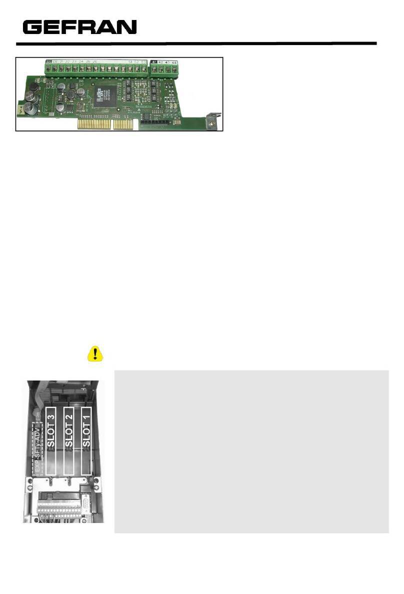
Refer to ADV200 Quick Start up manual, chapter “Installation of optional cards”:
the card must be inserted on slot 3.
1.6. Connections
Bus media
The GDNet option module incorporates one 100 BASE-TX RJ45 interfaces (A
Port). The second port (B) is not enabled and must not be used.

EN- 3
Cabling considerations
To ensure long-term reliability it is recommended that any cables used to connect
a system together be tested using a suitable Ethernet cable tester, this is of par-
ticular importance when cables are constructed on site.
Cable
To connect to the Bus, use a standard category 6 shielded Ethernet cable, accord-
ing to TIA/EIA-568A.
Cabling issues are the single biggest cause of network downtime. Ensure cabling
is correctly routed, wiring is correct, connectors are correctly installed and any
switches or routers used are rated for industrial use. Ofce grade Ethernet equip-
ment does not generally offer the same degree of noise immunity as equipment
intended for industrial use.
Maximum network length
The main restriction imposed on Ethernet cabling is the length of a single segment
of cable.
The ADV-GDNet module has one 100BASE-TX Ethernet port, which support seg-
ment lengths of up to 100m. This means that the maximum cable length which can
be used between one ADV-GDNet port and another 100BASE-TX port is 100m
however it is not recommended that the full 100m cable length is used.
The total network length is not restricted by the Ethernet standard but depends on
the number of devices on the network and the transmission media (copper, ber
optic, etc.).
ADV-GDNet terminal descriptions
The ADV-GDNet module has an Ethernet RJ45 port for the EtherNet/IP network:
port “A” is used for the link, port “B” is not connected and must not be used.
GDNet terminal connections
Pin A - IN (J1( Pin B - OUT (J2)
1 Transmit + 1 Not used
2 Transmit - 2 Not used
3 Receive + 3 Not used
4 Not used 4 Not used
5 Not used 5 Not used
6 Receive - 6 Not used
7 Not used 7 Not used
8 Not used 8 Not used

EN- 4
Network topology
The following gure shows a connection between the single cards. Address via
rotary switch 1...15.
Minimum node-to-node cable length. Ethernet standards do not specify a mini-
mum recommended cable length.
ADV200
EXP-ETH-GD-ADV200
ADV200
EXP-ETH-GD-ADV200
ADV200
EXP-ETH-GD-ADV200
PLCSwitch
Example, connection via switch to Gefran PLC.
To avoid possible problems it is recommended that you allow sufcient cable
length to ensure good bend radii on cables and avoid unnecessary strain on con-
nectors.

EN- 5
1.7. Leds - Rotary switch - Jumper - Terminal
There are two Ethernet diagnostics LEDs on the RJ45 connector on port A of the
card.
LEDs Descriptions
Reference Name Color Function
PortA
Link yellow Indicates that a connection has been established
Data green Indicates that data exchange is in progress
The EXP-ETH-GD-ADV card includes the following hardware diagnostics LED:
LEDs Descriptions
Reference Name Color Function
H1 RUN green Indicates that rmware is running on the microprocessor.
H2 FAIL red Indicates a system malfunction.
H3 PW yellow Indicates that the card is connected to the supply voltage.
The EXP-ETH-GD-ADV card includes a 16-position rotary switch and a 2-position
dip switch for congurations:
Rotary switch and dip switch descriptions
Reference Name Function
S2 Rotary Switch
Switch di congurazione nodo rete GDnet 1-9 A-F.
Node Number:
0=rete non attiva
1..9 = 1..9
A = 10
B = 11
C = 12
D = 13
E = 14
F = 15
S1 DIP Switch 2 posizioni Al momento non usato
Other:
Reference Function
P2 JUMPER : if terminals are mounted, the jumper must be installed in position 2-3.
TB1 TERMINAL : If contacts are mounted they must be left NOT CONNECTED.

EN- 6
1.8. Optional card recognition
T+ T- EN LO C ILim n:0 AL
MESSAGE 01
Option detect slot 3
Code: 0204H-516
At power-on, the drive recognizes the presence of optional card in the expansion slot 3, this
message is shown on the display.
T+ T- EN LO C ILim n:0 AL
02.19 PA R: 534
Slot3card type
RTE
Value 516
T+ T-ENLOC ILim n:0 AL
01 MONITOR
02 DRIVE INFO
03 STARTUP WIZARD
04 DRIVE CONFIG
On 02 DRIVE INFO menu, select the PAR 534 Slot 3 card type to read the recognized card
type.
Value Description Card type
0 None -
516 RTE EXP-ETH-GD-ADV
255 Unknown -

EN- 7
2. Start-up guide
This section is intended to provide a generic guide for setting up module with a
master/controller PLC. It will cover the basic steps required to get cyclic data com-
municating using the GDNet protocol on the module.
Conguring the -GDNet module for cyclic communications
In the GDNet protocol conguration, the instances for describing cyclic data
exchange have a xed size, which must correspond to the settings on the master
and on the device.
The network transmission speed is xed. The module must be associated with a
unique Node Number address.
Check the Ethernet diagnostics LEDs on port A to make sure the Ethernet cable is
connected properly to the GDNet module on the drive. See the table in chapter 1.7
for a description of these LEDs.
Check that the node is set to Operational on the master device.
Decide which input/output data are to be sent cyclically (objects and/or pa-
rameters). The input/output data associated with cyclic data exchange can be
congured directly via the drive parameters (setting in the FIELDBUS M2S and
FIELDBUS S2M menus).
It is important to set a data area size that is compatible with the Master and the
GDNet device: if set on the drive, make sure the number of bytes used corre-
sponds to the size of the I/O area set on the master. The size in bytes used by
the drive is obtained from the settings in the FIELDBUS M2S and S2M menus, by
adding the size in bytes of each parameter set via the relative “Fieldbus M->S n
sys” or “Fieldbus S->M n sys” parameter, according to the table below:
Not assigned The datum in question and all subsequent data
(even if assigned) do not contribute to the I/O area.
Count16,Par16,Fill16,MdpPlc16,Eu 2 byte
Count32,Par32,Fill32,MdpPlc32,Eu float 4 byte
The I/O data area of the “Master to Slave (M2S)” and “Slave to Master(S2M)” drive
are associated as follows:
• M2S <-> ODB
• S2M <-> IDB
Download the conguration to the master
After downloading the conguration to the master the LED link Data on Port A
should ash.
If congured correctly, when the master passes to “Run” mode (drive parameter
4014 “Fieldbus State” passes to “Operational”) the output values sent by the master
are visible in the drive parameters associated with the channels congured in the
“Fieldbus M2S” menu, while the input values received are updated to the values of
the “Fieldbus S2M” menu parameters.
Menu Fieldbus
To enable the EXP-ETH-GD-ADV card set PAR 4000 Fieldbus type as “RTE”.
The following parameters are available in the COMMUNICATION->FIELDBUS

EN- 8
CONFIG menu:
PAR Parameter description Type Default value Attr
4000 Fieldbus Type Enum Attr G Write
4006 Fieldbus address 2 byte unsigned 0 Write
4010 Fieldbus M->S enable Enum 0n Write
4012 Fieldbus alarm mode 2 byte unsigned 0 Write
4014 Fieldbus state Enum Stop Read only
4398 RTE protocol GDNet None Read only
Note: The drive must be reset to make all eldbus settings and congurations effective.
• Fieldbus address = not used. The master device identies the card by the
Node Number set using Rotary Switch S2.
• Fieldbus M->S enable = if set to Off the data the PLC sends the drive (master
to slave) are not updated anymore by the drive and the current values are
maintained.
• Fieldbus alarm mode = if set to On the drive generates Opt Bus Fault errors
relating to the loss of communication (Bus Loss) even when the drive is not
enabled.
• Fieldbus state = state of the communication on the RTE network :
GDNet Stato bus di campo PAR 4014
Cfg Pre-operational
Ope Safe-op (if there is a type H fault: see chapter 4)
Ope Operational (no type H fault)
Mis Safe-op
See chapter 3.1 GDNet communication states.
Conguration example
This chapter provides an example of how to congure the parameters of ADV200
drives so that they can be read and written by a PLC via the processing channels
(Dati di input/output cyclic datas). See the chapter “2.2.2. Writing Output data” on
page 13 for the conguration channels.
The paragraph “2.1. GDNet master device settings (PLC)” on page 8 provides the
information required on a GDNet master controlling a machine. The paragraph
“2.1.3. Composition of I/O” on page 11 contains basic information for programming
the ADV200 drive starting from the factory settings.
2.1. GDNet master device settings (PLC)
This section contains an example of data exchange seen from the PLC side. This
is the data normally contained in the machine specications in the case of applica-
tions controlled by a GDNet master. The ADV200 drive is available in Gf_Net in
the Catalog when using a GDNet master device.

EN- 9
The drive settings, node number and a Gf_eXpress le can therefore be cong-
ured with the conguration of the data exchanged:
2.1.1. Description of Master -> Slave cyclic input/output data communication
There are two parameters to be written via the processing channels. The rst is a
control word, in which the single bits contain certain commands (e.g. enable, start,
etc. ). The second processing channel contains the ramp reference 1 (RampRef1)
in rpm.
GDNet cyclic input/output data: Master -> Drive (max 16 words)
Position Description Format Unit of Measure
Word1 M -> S Control word 16 bit Word ...
Word2 M -> S Ramp Ref 1 Int 16 bit rpm
Word3 M -> S
Word4 M -> S
Word5 M -> S
Word6 M -> S
Word7 M -> S
...
...
Word16 M > S

EN- 10
CONTROL WORD
Bit Description Remarks
0 EnableCmd Enable command from PLC
1 StartCmd Start command from PLC
2 Free
3 Free
4 Free
5 Free
6 Free
7 Free
8 Digital Out3 Digital output 3 command from PLC
9 Digital Out4 Digital output 4 command from PLC
10 Free
11 Free
12 Free
13 Free
14 Free
15 Free
2.1.2. Description of Slave -> Master cyclic input/output data communication
The GDNet master reads three parameters from the drive. The rst contains a
status word in which the single bits carry information about the status of the drive
(e.g. DriveOk). The second parameter is the actual speed in rpm. The third param-
eter contains the value of analog input 2.
GDNet Slave > Master cyclic input/output data (max 16 Words)
Position Description Format Unit of Measure
Word1 S -> M Status Word 16 bit Word BitWide
Word2 S -> M Actual Speed Int 16 bit rpm
Word3 S -> M Analog Input 2 Int 16 bit
Word4 S -> M
Word5 S -> M
Word6 S -> M
Word7 S -> M
...
...
Word16 S -> M
STATUS WORD
Bit Description Remarks
0 EnableState Drive enabled
1 Drive Ok Drive Ok
2 Speed is zero Zero speed threshold
3 Free
4 Free
5 Free
6 Free
7 Free
8 Digital Input 4 ADV200 digital input 4 status
9 Digital Input 5 ADV200 digital input 5 status
10 Free
11 Free
12 Free
13 Free
14 Free
15 Free

EN- 11
2.1.3. Composition of I/O
Settings relating to IDB or ODB data exchanged cyclically can be congured on the
GDNet master device by importing the .gfe drive settings le.

EN- 12
2.2. ADV200 Conguration
The example given in this section is based on the assumption that the parameters
of the ADV200 drive are the factory settings (Default parameter command).
The I/O data exchanged via the EXP-ETH-GD-ADV200 card can be congured by
associating them with the drive parameters. The data written by the GDNet scan-
ner to the drive are associated with output instance 100 and congured on the
drive via the parameters in the “Fieldbus M2S” (Master to Slave) menu.
The data read by the master are associated with input instance 101 and con-
gured on the drive via the parameters in the “Fieldbus S2M” (Slave to Master)
menu.
Parameters can be either 2 or 4 bytes long, depending on the associated format,
selected via the “Fieldbus M2S n sys” and “Fieldbus S2M n sys” settings.
There are 16 input channels and 16 output channels in which from 0 to 16 data
can be congured, as long as the total number of bytes requested does not ex-
ceed 32 input bytes and 32 output bytes.
Example:
It is possible to have:
• from 0 to 16 data items of 2 byte
• 1 datum of 4 bytes + from 0 to 14 data items of 2 bytes
• 2 data items of 4 bytes + from 0 to 12 data items of 2 bytes
• ...
• 8 data items of 4 bytes
The data exchanged via the PDC can be of two types:
• drive parameters
• variables of an MDPlc application
2.2.1. Reading states and writing commands to the drive
Specic parameters are available for reading states and writing commands to the
drive, in which each bit can be programmed and associated with a function.
Commands can be sent to the drive using the functions of PAR 4452 Word
decomp src. The meaning of the single bits is programmable. It can be set on a
Field bus M->Sn channel as Count 16.
The drive state is read in PAR 4432 Word Comp mon, programmable on any
Field bus S->Mn channel as Count 16. The meaning of each single bit can be se-
lected by the user using PAR 4400 Word Bit 0 src ... PAR 4430 Word Bit 15 src.
For a detailed description of these parameters see the drive manual.
2.2.1.1. FIELDBUS CONFIG menu
Note: The drive must be reset to make all eldbus settings and congurations effective.
Congure the eldbus menu parameters as shown below:

EN- 13
I/O data exchange is only actually active when parameter 4014 “Fieldbus state”
is set to “Operational”. In all other cases, the master has not started to exchange
I/O data with the EXP-ETH-GD-ADV200 card. This could be due to incorrect as-
sembly instance conguration, for example if the size set on the master is not the
same as that obtained from the settings in the “Fieldbus M2S” and “Fieldbus S2M”
menus, or if the master is not in the “Run” state.
If parameter 4014 “Fieldbus state” is “Operational” the I/O data are updated with
the programmed parameter values. The drive can only be enabled in this state.
2.2.2. Writing Output data
2.2.2.1. Fieldbus M2S Menu
Wdecomp is used to congure the control word. The Wdecomp conguration on
the rst M -> S word (“Export” mode) is shown below:
Now simply connect the single Wdecomp bits. For Commands the drive must be
set to “Remote” and “Digital” mode, as explained in the ADV200 manual.

EN- 14
Congure the rst two bits in the commands menu as shown below:
Congure bits 8 and 9 of the “Command word” as shown below (Digital Outputs
menu):

EN- 15
2.2.2.2. REFERENCES Menù
The second word is congured in the “References” menu:
After sending a save command and re-starting the drive, check that the M -> S
channels have been congured correctly as shown (Html page):
2.2.3. Writing Input data
2.2.3.1. FIELDBUS S2M Menu
These channels are congured in the Fieldbus S2M menu. Use Wcomp to cong-
ure the rst channel.
S2M conguration is shown below:

EN- 16
Wcomp conguration is shown below:
Save and then re-start the drive to check the correct conguration of the Slave ->
Master channels in the same way:

EN- 17

EN- 18
2.3. Communication check
Some notes/suggestions for checking communication.
- Cyclic input/output data communication is only active if the state of parameter
4014 Fieldbus state is “Operational”. Check the status using Gf_eXpress or
the expansion card LED.
- For Master -> Slave communication in the FIELDBUS M2S menu you can
check the value received by the communication channel (e.g. for the rst chan-
nel it is the Fieldbus M->S1 Mon parameter).
- For EU (engineering unit) communication, remember that the value read on
the Mon parameters of FIELDBUS MS2 is in internal units (see conversion
tables on chapter 5.0 SYSTEM INTERNAL VARIABLES, “ADV200, Write the
applications with the MDPlc” manual available on www.gefran.com).

EN- 19
3. GDNet Protocols
• GDNet is a protocol with a cyclical, isochronous architecture based on
switched Ethernet 100BaseT, used to exchange process data with I/O and
motion devices.
• It enables connection between one master and N slave devices
• Communication is via star connection topology (Switched Ethernet) backed
by standard “store&forward” switching.
• Once the Length/Type eld equal to 0xFFAE has been identied, the protocol
supports 3 sequential network scans (Nr=1..3)
Network1 -> Network2 -> Network3 -> Network1 -> Network2 -> ….
• Each network supports the continuous scanning of Ns slave devices
(Ns=1..7), where a slave device is dened as a typical message (comprising
48 input words and 48 output words, of which 16+16 usable by the EXP-ETH-
GD-ADV) supplemented with sporadic access data structures (255 contigu-
ous data structures each composed of a maximum of 64 words).
Auto-conguration. The network auto-congures at reset (within less than 100
msec with 7 slave devices). Conguration messages are sent along with the typi-
cal cycle messages.
3.1. GDNet communication states
The GDNet master device behaves differently depending on its state.
Possible states are listed in the table below. Note that the HardReset state is not
part of the communication as it is not enabled. Net_ID is the network identier
(1..3), Slave_num is the slave device identier (1..7) and CONFIG01 refers to the
main data area (for further details, see Database and Alias).
Nome
stato
Net_ID Slave_ID Risposta a richiesta
database
Uscite slave
HardRESET 1 0 Non esiste comunicazione Come da reset hardware
SoftRESET 1 0 Messaggio di ALIAS
CONFIG01
Come da reset hardware
PROG Net_ID Slave_ID Database di INPUT corrente Congelate
OPERATE Net_ID Slave_ID Database INPUT corrente Database OUT corrente
FAIL Net_ID Slave_ID Database INPUT (ultimo
valido)
Come da reset hardware

EN- 20
SoftRESET PROG
FAIL OPERATE
Reset HW
Power ON
ID setting
(CONFIG01 writing)
Go_Operate
(complex
command)
Serious fault
W.dog COM
Serious fault
W.dog COM
HardRESET
Reset SW (complex command)
always
Reset SW
Reset SW
Reset SW
Go_Prog
HardRESET state
In the RESET state, the slave device is in a known position with the structures
initialised at known values and the outputs set to safe state.
The communication structures are reset and communication is not active (mes-
sages received are ignored).
Low level system start-up procedures are performed (e.g. PLL, MAC, etc.).
After completing all these procedures and thus after a certain length of time, the
SoftRESET state is automatically enabled.
SoftRESET state
In the SoftRESET state the slave device maintains the structures in their previ-
ous state. Only the Net_ID, Slave_ID, position and previous MAC address of the
master device are cancelled at this stage.
The outputs are set to safe and the slave device only sends messages if ques-
tioned.
All slave devices behave in the same way when in the SoftRESET state:
- they do not check whether messages were sent by the master device (i.e. the
source MAC address is not checked)
- they disregard outputs from the master device
- they disregard their own inputs for database construction
This status is maintained until the slave is completely set, (including Net_ID and
Slave_ID). Then the status switches to “Prog”.
PROG state
In PROG state programming can be completed by writing the other cong les.
The address of the slave device must contain the NET_ID value and slave
number.
In PROG state the slave
- activates the communication watchdog
- the outputs are frozen in the previous state
- checks the MAC address of incoming messages (except synchronisation)
Table of contents
Other gefran Computer Hardware manuals