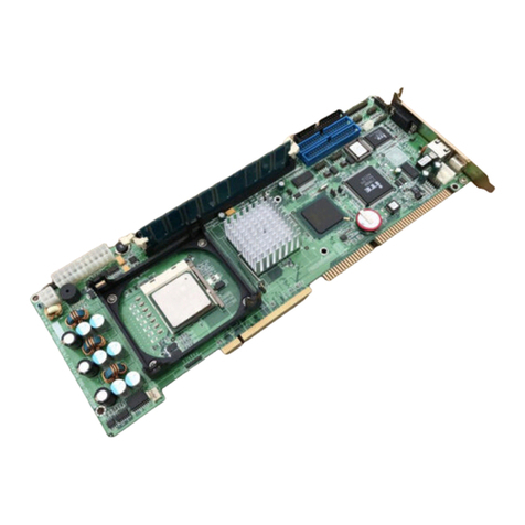
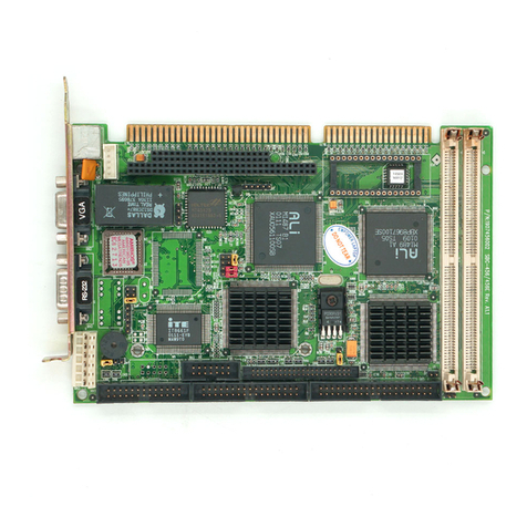
Aaeon SBC-551 User manual

SBC-551/552
Half-Size PISA/ISA Pentium CPU Card

FCC STATEMENT
THISDEVICECOMPLIESWITHPART15FCCRULES.OPERA-
TIONISSUBJECTTOTHEFOLLOWINGTWOCONDITIONS:
(1)THISDEVICEMAYNOTCAUSEHARMFULINTERFER-
ENCE.(2)THISDEVICEMUSTACCEPTANYINTERFERENCE
RECEIVEDINCLUDINGINTERFERENCETHATMAYCAUSE
UNDESIREDOPERATION.
THIS EQUIPMENT HAS BEEN TESTED AND FOUND TO
COMPLY WITH THE LIMITS FOR A CLASS"A" DIGITAL
DEVICE, PURSUANT TO PART 15 OF THE FCC RULES.
THESE LIMITS ARE DESIGNED TO PROVIDE REASON-
ABLE PROTECTION AGAINTST HARMFUL INTERFER-
ENCEWHEN THE EQUIPMENT IS OPERATED IN A
COMMERCIAL ENVIRONMENT. THIS EQUIPMENT GENER-
ATES,USES, AND CAN RADIATE RADIO FREQUENCY
ENERGYAND, IFNOTINSTATLLEDANDUSED IN ACCOR-
DANCEWITH THE INSTRUCTION MANUAL, MAY CAUSE
HARMFUL INTERFERENCE TO RADIO COMMUNICA-
TIONS. OPERATION OF THIS EQUIPMENT IN A RESIDEN-
TIALAREA IS LIKELY TO CAUSE HARMFUL INTERFER-
ENCE IN WHICH CASE THE USER WILL BE REQUIRED
TOCORRECT THE INTERFERENCE AT HIS OWN EX-
PENSE.

Acknowledgements
AMD is a trademark of Advanced Micro Devices, Inc.
Award BIOS is a trademark of Award Software International, Inc.
AutoCAD and AutoShade are trademarks of Autodesk, Inc.
CHIPS Logotype is a registered trademark. Chips 65554 is a
trademark of Chip and Technologies, Inc.
Cyrixisa trademark of Cyrix Corporation.
IBM, PC/AT, PS/2, and VGA are trademarks of International
Business Machines Corporation.
Intel and Pentium are trademarks of Intel Corporation.
Lotus 1-2-3 and Symphony are trademarks of Lotus Development
Corp.
Microsoft Windows® and MS-DOS are registered trademarks of
Microsoft Corp.
SiS is a trademark of Silicon Integrated System Corp.
SMC is a trademark of Standard Microsystems Corporation.
UMC is a trademark of United Microelectronics Corporation.
VESA®is a registered trademark of Video Electronics Standards
Association.
All other product names or trademarks are properties of their
respective owners.
PartNo.2007551000 SBC-551/552 1st Edition
Printed in Taiwan Aug 1998

Packing list
Before you begin installing your card, please make sure that the
following materials have been shipped:
• 1 SBC-551/552CPUCard
• 1 User Manual (this book)
• 1 Hard disk drive (IDE) interfacecable (44 pin)
• 1 Floppy disk drive interface cable (34 pin)
• 1 6-pin mini-DIN dual outlet adapter for keyboard and PS/2
mouse
• 1 Parallel port adapter (26 pin) and COM1 adapter (9 pin) kit
• 4 Utility disks with SiS 5598 utility programs and drivers
• 1 bag of screws and miscellaneous parts
If any of these items are missing or damaged, contact your distribu-
tor or sales representative immediately.

Contents
Chapter 1: General Information ....................... 1
Introduction ........................................................................... 2
Features.................................................................................. 3
Specifications ......................................................................... 4
Board layout (SBC-551)(PISA Slot) ................................... 6
Board layout (SBC-552)(ISA Slot)...................................... 7
Card dimensions.................................................................... 8
Chapter 2: Installation ....................................... 9
Jumpers and connectors .................................................... 10
Locating jumpers, connectors and sockets .................... 11
Setting jumpers ................................................................... 12
Safety precautions ............................................................... 13
Installing the CPU............................................................... 14
SIMM installation/removal................................................ 15
Hardware reset (JP1) ......................................................... 16
Thermal alarm LED (JP2) ................................................. 16
Internal SVGA setting (JP3) ............................................. 16
Clear CMOS data (JP4) ..................................................... 17
CPU type select (JP5) ........................................................ 17
CPU external clock selection (JP7)................................. 18
CPU clock ratio (JP8)......................................................... 19
Vcore voltage selection (SW1).......................................... 20
DOC address (JP9)............................................................. 21
RS-232/422/485 selection (JP10) ..................................... 20
PS/mouse enable/disable (JP11) ....................................... 22
CPU jumper setting example ............................................ 23
Hard disk LED connector (CN1) ..................................... 30
IDE hard drive connector (CN2) ...................................... 28
Floppy drive connector (CN3) .......................................... 30
Parallel (printer) port connector (CN4)........................... 31

Fan connector (CN5) .......................................................... 32
USB connector (CN6)......................................................... 32
Serial port connectors (CN10, CN7)................................ 33
RS-232 connector (CN10) ......................................................33
RS-232/422/485 connector (CN7)...........................................34
Reserved IR connector (CN8).......................................... 35
Power connector (CN9)...................................................... 35
VGA connector (CN11) ...................................................... 36
KB/PS2 mouse connector (CN12).................................... 37
DiskOnChip socket (U15)................................................. 38
Chapter 3: Award BIOS Setup .......................... 41
System test and initialization ............................................. 42
Systemconfigurationverification ............................................42
AWARD BIOS setup............................................................43
Entering setup..........................................................................43
Standard CMOS setup ....................................................... 44
BIOS features setup ........................................................... 46
CHIPSET features setup ................................................... 50
Power management setup.................................................. 53
PnP/PCI configuration setup ............................................. 59
Load BIOS defaults/Load SETUP defaults ..................... 62
Integrated Peripherals Setup ............................................ 63
Supervisor/user password setting .................................... 67
IDE HDD auto detection ................................................... 69
HDD low level format utility.............................................. 71
Save & exit setup................................................................ 72
Exit without saving ............................................................. 73
Chapter 4: SiS 5598 VGA Drivers ...................... 75
System requirements.......................................................... 76
Windows 95 .......................................................................... 76
Windows 95 (display driver installation) ..................................76
Selecting resolution, color depth, and refresh rate...................77
Windows 3.3.
3.3.
3. x ........................................................................ 78

Installing ..................................................................................78
Graphics setup.........................................................................78
Power saving setup in Windows 3.x........................................79
NT 3.5X................................................................................. 79
Windows NT 3.5x display divers installation ...........................79
Selecting resolution and color depth ........................................80
NT 4.0 ................................................................................... 80
windows NT 4.0 display drivers installation ............................80
Selecting resolution and color depth ........................................81
DOS ....................................................................................... 82
VGAutility ..............................................................................82
Video uode uetting...................................................................82
Frame rate setting ...................................................................82
Power saving setting ...............................................................82
Appendix A: Programming the Watchdog
Timer ............................................. 83
Programming the watchdog timer .................................... 84
How to program the watchdog timer ......................................84
Demo program ........................................................................85


Chapter 1 General Information 1
1
General
Information
This chapter provides background
informationfor theSBC-551/552.
Sections include:
• Card specifications
• Board layout
CHAPTER

2SBC-551/552 User Manual
Introduction
TheSBC-551/552is an all-in-one SingleBoardComputer(SBC)
capable of handling the Intel Pentium P54C, P55C (MMX),AMD
K6,aswell as theCyrix6x86(M1) and 6x86MX(M2)CPUs.
Reliability,performance, flexibility, andadequateexpansion
capabilities are essential qualities for SBCs and their embedded
applications and the SBC-551/552 provides all of these.
The Smart Temperature Control technology (LM75 chip) monitors
the CPU temperature and automatically slows down the CPU
frequency when the CPU temperature exceeds a specified safe
range, helping your system recover from abnormal temperature
fluctuations.
TheSBC-551/552 supports the M-Systems DiskOnChip 2000
(optional) which is a new generation of high performance single-
chip Flash Disk. It provides a Flash Disk (as a BIOS expansion)
which doesn't require any bus, slots, or connectors. It is also the
optimal solution for Single Board Computers because of its small
size, easy integration, plug-and-play functionality, and its low
power consumption. The DiskOnChip is available in capacities
from 2MB to 72MB and fits in a standard 32-pin DIP socket.
The SBC-551/552 also includes a high speed, local bus IDE
controller which supports (through ATA PIO) mode 3 and mode 4
hard disks, Ultra DMA/33 (data transfer rates up to 33MB/sec) and
up to 2 IDE devices.
Onboard features include one high speed RS-232 serial port, one
RS-232/422/485serialport with 16C550 UARTs,onebidirectional
SPP/EPP/ECP parallel port, and a floppy drive controller. In
addition to the 486's 16 KB of onchip cache memory, the SBC-551/
552includes an extra 512 KB of pipeline-burst L2cachememery.
If program execution is halted by a program bug or EMI, the board's
watchdog timer can automatically reset the CPU or generate an
interrupt. This ensures reliability in unmanned or standalone
systems.

Chapter 1 General Information 3
TheSBC-551/552providestwo72-pinSIMM(SingleIn-line
Memory Module) sockets for intalling onboard system DRAM.
These sockets give you the flexibility to configure your system
from 4 MB to 128 MB of DRAM using the most economical
combination of SIMMs.
Features
•SupportsPentiumP54C/P55C(MMX),AMD K6, and Cyrix M1/M2
CPUs
•Half-sizePISAbusCPUCardforSBC-551,andhalf-size ISA bus CPU
CardforSBC-552
•Equipped with a switching power module supporting up to 10 Ampere
CPU power consumption
•DiskOnChip(SSD)upto72MB
•SiS5598 chipset: XGA controller integrated
•Bus Master IDE and Ultra DMA/33 supported
•LM75 supports CPU temperature & fan monitoring

4SBC-551/552 User Manual
Specifications
CPU: IntelPentiumMMX166~233MHz,AMD-K6/200~300AFR,Cyrix/
IBM/6x86MX-PR166~266GPandIDTwinchipC6180~225MHz
BIOS:AwardFLASHBIOS
Chipset:SiS5598
Businterface:PISABusforSBC-551,ISABus for SBC-552
Level2Cache:Onboard 512KB pipeline-burst L2 cache.
System memory: Two 72-pin SIMM sockets. Supports up to 128MB
DRAM.
DMAchannels:7
Interruptlevels:15
Battery:Lithium battery for data retention of up to 10 years.
EnhancedIDE:Supports up to two IDE devices. BIOS auto-detect,
supports PIO mode 4 and Bus Master. Also supports multi-word DMA
andUltra DMA/33.
FDD interface: Supports up to two floppy disk drives.
Parallelport:Configured to LPT1, LPT2, LPT3, or disabled. Supports
SPP,ECP, and EPP.
Serialports: One RS-232 and one RS-232/422/485 serial port. Ports can be
configured as COM1, COM2, COM3, COM4, or disabled individually. Two
16C550serialUARTs.
IrDA interface: One IrDA connector reserved for future use.
Keyboard/mouseconnector:6-pin mini-DIN connector supports standard
PC/AT Keyboard and PS/2 mouse.
USBconnectors:One USB connector onboard. (Support two USB
channels)
WatchdogTimer: Can generate a system reset, IRQ15, or NMI. Software
selectable time out interval (2 sec ~ 128 min, 1 sec/step).
Powermanagement: I/O peripheral devices support power saving and
doze/standby/suspend modes. APM 1.2 compliant
VGAcontroller:SiS5598

Chapter 1 General Information 5
Display memory: Supports shared system memory up to 4MB.
Displaytype: Supports aCRTdisplay.
Resolution:Support up to1024x768 @ 16.7M colors.
SSD interface: One 32-pin DIP socket supports the M-Systems DiskOn-
Chip2000series,memorycapacityfrom2MBto72MB.
CPUthermal: LM75 supportsCPUtemperature & fan monitoring.
Powersupplyvoltage:+5V(4.75Vto5.25V)
+12V(11.4V to12.6V)
PowerRequirement:
BareBoard: +5V@1.5A
PentiumMMX-200: +5V@6A
AMDK6-233: +5V@10A
Operatingtemperature:32°Fto140°F (0°Cto60°C)
Boardsize:7.3"(L)x 4.8"(W)(185mmx122mm)
Boardweight:0.23kg

6SBC-551/552 User Manual
Board layout (SBC-551)(PISA Slot)
14.318
5598
SIS
CPU
SOCKET
BAT
DiskOnChip
Winbond
iTE
IT8661

Chapter 1 General Information 7
Board layout (SBC-552)(ISA Slot)
14.318
5598
SIS
CPU
SOCKET
BAT
DiskOnChip
Winbond
iTE
IT8661

8SBC-551/552 User Manual
Card dimensions
185.00 178.00
122.00
98.50
19.50
D4x4

Chapter 2 Installation 9
2
Installation
This chapter explains setup procedures
fortheSBC-551/552hardware,including
instructions on setting jumpers and
connecting peripherals, switches and
indicators. Be sure to read all safety
precautions before you begin the installa-
tion procedure.
CHAPTER

10 SBC-551/552 User Manual
Jumpers and connectors
Connectors on the board link to external devices such as hard disk
drives, keyboard, or floppy drives. In addition, the board has a
number of jumpers that allow you to configure your system to suit
your applications.
The tables below lists the function of each of the board jumpers
and connectors:
Jumper Label Function
JP1 Hardware reset
JP2 Thermal alarm LED
JP3 Int VAG setting
JP4 Clear CMOS
JP5 Vio voltage setting
JP7 CPU clock setting
JP8 CPU frequency ratio
JP9 DOC address setting
JP10 RS-232/422/485 select
JP11 PS/2 mouse setting
SW1 CPU voltage setting
Connector Label Function
CN1 IDE LED connector
CN2 HDD connector
CN3 Floppy drive connector
CN4 Parallel (Printer) connector
CN5 Fan connector
CN6 USB connector
CN7 COM2 connector
CN8 Reserved IR connector
CN9 Power connector
CN10 COM1 connector
CN11 VGA connector
CN12 KB/PS2 mouse connector

Chapter 2 Installation 11
14.318
5598
SIS
CPU
SOCKET
BAT
DiskOnChip
Winbond
iTE
IT8661
Locating jumpers, connectors, and
sockets
Power
connector COM 1(CN10)
connector VGA(CN11)
Port Keyboard/
Mouse Port (CN12)
FDD
connector
(CN3)
JP5
SW1
JP2
JP4
JP7
Socket for
DiskOnChip
Award
Flash BIOS
PISA Bus
(PCI+ISA)
JP9
JP8
SiS 5598
Chipset
IDE
connector
(CN2)
Up to
128MB DRAM
Reset SW
(JP1)
IDE LED
(CN1) JP3
COM2 (CN7)
connector CN8
CN6
RS-232/422/485
select (JP10)
Parallel Port
connector
(CN4)
Fan connector
(CN5)
JP11 PS/2 mouse
Enable/Disable

12 SBC-551/552 User Manual
Setting jumpers
By setting the jumpers, you can configure your card to match the
needs of your specific applications. A jumper is the simplest kind
of electric switch. It consists of two metal pins and a small metal
clip (often protected by a plastic cover) that slides over the pins to
connect them. To close a jumper you connect the pins with the
clip. To "open" a jumper you remove the clip. Sometimes a jumper
will have three pins, labeled 1, 2, and 3. In this case you would
connect either pins 1 and 2 or 2 and 3.
The jumper settings are schematically depicted in this manual as
follows:
A pair of needle-nose pliers may be helpful when working with
jumpers.
If you have any doubt about the best hardware configuration for
your applications, contact your local distributor or sales represen-
tative before you make any changes.
13
2
Open Closed Closed 2-3
1 2 3
This manual suits for next models
1
Table of contents
Other Aaeon Computer Hardware manuals

Aaeon
Aaeon ETX-821 User manual

Aaeon
Aaeon PCM-8150 User manual

Aaeon
Aaeon HSB-668I User manual

Aaeon
Aaeon UP Squared 6000 Edge Computing Kit User manual

Aaeon
Aaeon SBC-860 User manual

Aaeon
Aaeon PFM-620S User manual

Aaeon
Aaeon UPN-EDGE-EHL01 User manual
Aaeon
Aaeon EMB-A50M User manual

Aaeon
Aaeon PCM-5335 User manual

Aaeon
Aaeon AEC-6643 User manual

Aaeon
Aaeon NEZHA-N97 User manual

Aaeon
Aaeon ETX-701 User manual

Aaeon
Aaeon EPIC-8526 User manual

Aaeon
Aaeon BOXER-8120AI User manual

Aaeon
Aaeon PCM-9150 User manual

Aaeon
Aaeon AEC-6638 User manual

Aaeon
Aaeon PICO-BT01 User manual

Aaeon
Aaeon HSB-810A User manual

Aaeon
Aaeon SBC-656 User manual

Aaeon
Aaeon HSB-800I User manual