PRODUCT MANUAL
Version 1.4
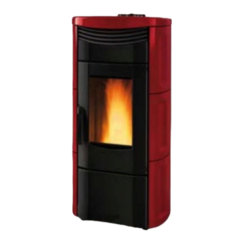
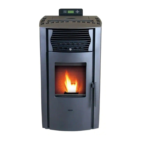
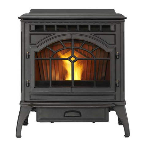
PELLET BOILER STOVE – AMANDA Diva 16,1 kW
6
2: IMPORTANT INFORMATION
2.1: GENERAL INFORMATION
Requesting information
If information is requested from the manufacturer of the
stove, always refer to the serial number and other
identifying data shown on the product’s identification
label.
Responsibility for installation
Gekas Metal Group accepts no responsibility for the work
carried out to install the stove, such responsibility lies with
the installer, who is required to carry our checks on the
flue and air intake and ensure installation is completed
correctly. Furthermore, all safety standards required by
relevant legislation in force in the country where the stove
is installed must be complied with.
Use
The stove must only be used in compliance with the
instructions provided in this manual, as well as with all
safety standards required by relevant legislation in force in
the country where the stove is installed.
2.2: GENERAL WARNING AND SAFETY INFORMATION
Observance of the introductory general warning
information is imperative.
•Read the entire manual thoroughly before installing
and putting the stove into service. Observe the
national provisions and laws as well as the
regulations and rules applicable locally.
•Gekas Stoves should only be installed in rooms with
normal humidity.
•Only approved transport equipment with enough
load carrying capacity may be used with your heating
appliance.
•Your heating appliance is not suitable for use as a
ladder or stationary scaffolding.
•The burning of fuel releases heat energy that lead to
extensive heating of the stove surfaces, doors, door
and operating handles, glass, flue pipes and possibly
the front wall and side walls. Refrain from touching
these parts without appropriate protective clothing
or equipment e.g. heat-resistant gloves or means of
operation.
•Make your children aware of this danger and keep
them away from the stove during heating.
•Only burn approved heating materials.
•The combustion or introduction of highly flammable
or explosive materials such as empty spray cans etc.
in the combustion chamber and storing them near
the stove is strictly prohibited due to the danger of
explosion.
•Use heat-resistant gloves to open the door of your
stove.
•Make sure that no embers fall out of the combustion
chamber onto inflammable material.
•Placing non-heat resistant objects on the stove or
near it is prohibited.
•Do not place clothing on the stove to dry.
•Laundry racks etc. must be placed at enough distance
to the stove – ACUTE DANGER OF FIRE!
•When your stove is burning, the use of highly
inflammable and explosive materials in the same or
adjacent rooms is prohibited.
•If the stove is heated in continuous operation, the
cleaning intervals are shorter. Increased wear,
especially of the thermally stressed parts, is the
result. Please therefore strictly follow the
requirements for cleaning and maintenance!
Warning
Waste and liquids may not be burnt in the stove!
Note
To prevent your stove’s internal components from
overheating, do never cover the convection fins.
Note
CAUTION when filling the pellet hopper. The opening of
the pellet hopper is sufficiently dimensioned to ensure
easy filling. Take great care that no pellets drop to the
convection fins and the hot stove body. This can cause a
lot of smoke.
Tip
We recommend refilling the pellet hopper when the stove
is inactive and still cold.
Note
Your stove will expand and contract during the heating
and cooling phase, respectively, which can sometimes lead
to slight bending or cracking noises. This is normal and
there is no reason to worry or complain.
