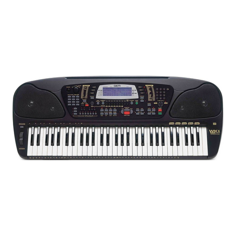
GEM WK1 User manual

1 ❏❏
❏❏
❏
Index
Soldering point.
Male connector.
Female connector.
M/F faston connector.
Test point.
Supply voltage. Logic supply ground.
Analog supply ground.
Chassis ground.
Earth ground.
Flag joined with one or more flags
GENERALMUSIC S.p.A. Sales Division: 47842 S.Giovanni in Marignano (RN) ITALY - Via delle Rose, 12
Phone +39(0)541/959511 - Fax +39(0)541/957404 - GENERALMUSIC on the NET: http://www.generalmusic.com
Wiring Connections & Block Diagram, Power Amplifier & Supply Board Schematic Diagram.3
Opening Instructions, Video Board Installation Instructions.2
Controls Panel Board (WK1 Oriental), Video Board (Optional) Schematic Diagrams7
Controls Panel Board (WK1), Dc/Ac Converter Board, LCD Display Board, Volume Board,
5Cpu & Sound Generator Board (WK1 & WK1 Oriental) Schematic Diagram
6
Modulation Board, Keyboard L/R Contact Board Schematic Diagrams
8Spare Part List
Timing Table
4
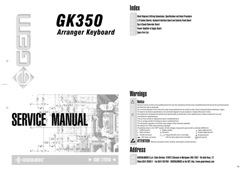
SERVICE MANUAL
CODE: 270275
Warnings
with the same signal name inscribed.
Address
ATTENTION
Observe
precautions when handling electrostatic sensitive devices.
Notice
Service must be carried out by qualified personnel only. Any tampering carried out by unqualified personnel during the guarantee period
will forfeit the right to guarantee.
For a correct operation of the instrument, after having switched off, be careful to wait at least 3 seconds before switching on again.
To improve the device's specifications, the schematic diagrams may be subject to change without prior notice.
All components marked by this symbol have special safety characteristics, when replacing any of these components use only
manufacturer's specified parts.
The (µ) micro symbol of capacitance value is substituted by U.
The (
Ω
) omega symbol of resistance value is substituted by E.
The electrolytic capacitors are 25Vdc rated voltage unless otherwise specified.
All resistors are 1/8W unless otherwise specified.
All switches shown in the "OFF" position. All DC voltages measured to ground with a voltmeter 20KOhm/V.
✔
✔
✔
✔
✔
✔
✔
✔
✔
✔
✔
✔
✒
☎

❏ ❏
❏ ❏
❏ 2
DRW
APP.
CKD
WRITTEN CONSENT BY GENERALMUSIC.
OR REPRODUCE THIS DOCUMENT WITHOUT
ALL RIGHTS ARE RESERVED, NO COPIES
GENERALMUSIC S.p.A. ITALY
PA R T:
DWG#
DISK:
REV:
PCB#
R. Morbidi
I. Vitri
G. Boccato 500949
22/11/01
Opening Instructions
Video Board Installation Instructions
1/1
Opening Instructions
1.
Turn off and disconnect the keyboard from mains line.
Carefully turn the keyboard over and remove all the screws
indicated by the arrows as shown in figure below.
Hold the top and bottom chassis tightly and turn it the right
way up.
Raise the lid and turn it vertically taking care not to
disconnect the cables.
2.
Place the Video Board (A) on its location (B) at the right of
the other boards as shown in figure below.
3.
Fix the Video Board (A) on the columns using the screws
(C), connect the cable in predisposed connector (D) as
shown in figure below.
4.
Close the instrument and check the properly operation
connecting a television and following the instructions on the
owner's manual.
A
B
C
D
C
Video Board Installation Instructions
TEST PROCEDURE
This procedure are not intended to repair a fault but only to check the proper instrument operations
after a repairing execution. The procedures that follow must be executed in the order specified.
Instrument and Tools
1) Dual trace oscilloscope.
2) Midi cable.
3) Television with RGB and S-VHS input sockets compatible with PAL and NTSC standards.
4) DIN/SCART, DIN/RCA and S-VHS cables.
5) Volume and Damper pedal.
6) Latest version of the appropriate Operating System Disk.
7) N.2 stereo jack plug.
Setup
✓Connect the television by RGB and S-VHS sockets.
✓Connect the stereo jack to the PHONES and AUX outputs.
Operating System Check
✓ Turn on the instrument.
✓Press MIDI/GENERAL for about 2 sec until the display shows "Damper Pedal:...", press PAGE>
until display shows "O.S. Release:" follows by the O.S. release date loaded into flash memory.
✓If an update is required put the Operating System disk into the disk drive and turn on again the
keyboard, the display shows “LOAD O.S.” then press ENTER to confirm.
NOTE: After any servicing operation an operating system re-loading is recommended.
Video Check & Adjustment (Optional)
✓The instrument starts with the video output set on PAL mode by default. Set TV input on RGB
mode, on the TV screen must appear the welcome message:
GEM WK1
Keyboard
✓Press MIDI/GENERAL for about 2 sec until the display shows "Damper Pedal:...", press PAGE>
until display shows "Video Type: PAL (Europe)” , press TEMPO/DATA> to select “NTSC (USA)”, on
TV screen must appear the above message wrote larger than in the previous PAL setting.
✓Disconnect or deselect the RGB input and select the S-VHS input (YC3) on TV.
✓Adjust if necessary the colours and the flicker on TV rotating the C12 capacitor trimmer.
✓Restore "PAL (Europe)” pressing TEMPO/DATA>.
✓Adjust if necessary the colours and the flicker on TV rotating the C11 capacitor trimmer.
✓Press ESCAPE button.
System Reset
✓Press UPPER 1 button and 1, 2, and 3 of numeric keypad simultaneously to reset the instrument,
the display shows “System RESET”. This procedure restore the initial manufacturer memory
configuration.
Keyboard Check
✓Play all white and black keys taking care to the uniformity of the dynamic response.
Controls Panel Check
✓Make sure that each single push button on the control panel operates correctly checking the
correspondance with the display visualization if exist and/or the respective LED.
Ram Back Up Check
✓Press TRANSPOSE “#”and display shows below TRANSPOSE “1”.
✓Switch off the instrument and wait at least 20 sec. When you switch on the instrument be sure
display shows the same “TRANSPOSE”number.
✓NOTE: the instrument have an internal re-chargeable NiCd battery that insures the data backup
for a maximum of 30 days, therefore it is recommended to hold switched on the instrument for at
least 8-10 hours after a long time of inactivity.
Headphones Check
Check the level from the output sockets as follow:
✓Connect the dual trace oscilloscope to the tip and sleeve contacts of the stereo jack plugged into
PHONES 2, set it at 2ms/div. 2V/div.
✓Press 68 on SOUNDS numeric keypad, the display will show "68:OBOE".
✓Disable REV/CHO by pressing it correspondent button.
✓Set MASTER VOLUME potentiometer to its maximum.
✓Play the note key C4 (61 note keyboards normally starts from C2) and verify with the oscilloscope
the output levels: their must be 5.5±0.5Vpp.
✓Move the oscilloscope probes to the stereo jack plugged into AUX OUTPUTS, the scope shows
two traces with 0.8Vpp ±5% each.
Pedals Check
✓Plug in the PEDAL VOLUME to its socket, it vary the level from 0 (no sound) to the level set by
MASTER VOLUME potentiometer.
✓Plug in the switch pedal to the DAMPER jack socket, press down the pedal and then press a note
key: the instrument plays the note, release the note key and the sound holds on, release the pedal
and the sound shuts off.
✓NOTE: the type of pedal (normally closed or normally open) is recognized at the moment of a
SysReset or when the instrument is switched on, the instrument asummes that the pedal is
normally open if none pedal is plugged into the socket, this is the reason because a pedal
normally closed plugged after you have switched on the instrument operates in opposite way.
Midi In/Out and Computer Socket Check
✓ Set on UPPER 1 section only and make a loop between MIDI OUT and IN by means the midi
cable.
✓Set UPPER 1 to local off by select MIDI/GENERAL for about 2 sec until the display shows
"Damper Pedal:..."
✓Press PAGE> until display shows "MIDI local:...".
✓Turn off track 8 by select F8, the respective "ON" text flashes, and press <TEMPO/DATA then
display shows "--".
✓Now each keyboard event will be send thru the midi external loop and played by the internal
generation.
✓Restore track 8 to local on pressing TEMPO/DATA> then display shows "ON".
✓Press 4 times <PAGE until display shows “Serial Computer: OFF”.
✓Press CURSOR 3 times and then press TEMPO/DATA> until display shows “MAC”
✓Connect the CH1 probe of the oscilloscope at PIN 1 of the COMPUTER socket and its ground
clip at PIN 4, set it at 200uS/div. 2V/div.: the trace must show a 1MHz signal with 5V of amplitude
centred on 0V (±2.5V).
✓Connect the CH2 probe of the oscilloscope at PIN 6 of the COMPUTER socket and its ground
clip at PIN 4, set it at 500uS/div. 10V/div.: playing some notes on the keyboard, the CH2
oscilloscope trace must show a sequence of pulses with 24V of amplitude centred on 0V.
✓Pressing TEMPO/DATA> select “PC1”or “PC2”to configure the instrument link for a PC.
✓Playing some notes on the keyboard you must see the same previous pulses onto the
oscilloscope screen.
✓Press ESCAPE.
Floppy Disk Check
✓Insert a 3.5" diskette containing a standard midi file .MID.
✓Press FLOPPY DISK, display shows "DIRECT: songname.MID", pressing TEMPO/DATA> the
display will show: "LOAD:songname.MID", press ENTER to confirm, the display shows "Loading
into memory" and the keyboard stops during this process.
✓Press START/STOP and the song will start to play.
✓Press again FLOPPY DISK, display shows "DIRECT: songname.MID", pressing TEMPO/DATA>
two times the display will show: "SAVE: Song SMF Perform", press ENTER 3 times to confirm, the
display shows "Saving on disk" and the keyboard stops during this process.
Sound ROM test
✓Select sound 00 and play some note checking its out, repeat the check with sound 33, 66, 99,
127, select SINGLE TOUCH PLAY, press START DRUM and play a chord on the keyboard left
part: check the correct style and sound; repeat the check for styles 33, 66, 88 also.
Reliability Check
Before reassembling the instrument and before deliver it to the user, it is a goal verify its reliability:
To do that switch it off, or leaving it switched on but operating with greatest caution, carefully shake
the boards and connections inside it using an insulated tool (for example the handle of the
screwdriver) to find wrong contacts and so on.
Turn on the instrument and verify that it operates correctly.

3 ❏❏
❏❏
❏

❏ ❏
❏ ❏
❏ 4

5 ❏❏
❏❏
❏

❏ ❏
❏ ❏
❏ 6

7 ❏❏
❏❏
❏

❏ ❏
❏ ❏
❏ 8
Spare Part List
Legend
EU = Specify European Version (230Vac)
US = Specify United States Version (115Vac)
WK1 = WK1 ersion only
WK1-Oriental = WK1-Oriental ersion only
Code Description
Optional Accessories
130301 2mt Midi Cable
970398 Video Interface (PAL Version)
970401 Video Interface (NTSC Version)
271342 * Video Board Installation Instructions
130317 * DIN/SCART Video Cable (Pal)(EU)
130428 * DIN/RCA Video Cable (Ntsc)(US)
120028 * M3x6tc Black Screw
Accessories
MDL345032 Music Stand
955881 WK1 Demo Disk
955880 WK1 Operating System Disk
271340 Owner's Manual (Italian-English-French-German)
271354 Owner's Manual (English-Arabian)
970315 230Vac/12Vdc Adapter 2.2A (EU)
970316 115Vac/12Vdc Adapter 2.2A (US)
Note: Spare part a ailable entirely only.
Cabinet Assembly
MDL665003 Left Speaker Grid
MDL665002 Right Speaker Grid
MDL655069 <+100> Circular Actuator (WK1)
MDL655089 <+100> Circular Actuator (WK1-Oriental)
MDL655068 <+> Circular Actuator (WK1)
MDL655088 <+> Circular Actuator (WK1-Oriental)
MDL655067 <-> Circular Actuator (WK1)
MDL655087 <-> Circular Actuator (WK1-Oriental)
MDL655066 <0> Circular Actuator (WK1)
MDL655086 <0> Circular Actuator (WK1-Oriental)
MDL655065 <9> Circular Actuator (WK1)
MDL655085 <9> Circular Actuator (WK1-Oriental)
MDL655064 <8> Circular Actuator (WK1)
MDL655084 <8> Circular Actuator (WK1-Oriental)
MDL655063 <7> Circular Actuator (WK1)
MDL655083 <7> Circular Actuator (WK1-Oriental)
MDL655062 <6> Circular Actuator (WK1)
MDL655082 <6> Circular Actuator (WK1-Oriental)
MDL655061 <5> Circular Actuator (WK1)
MDL655081 <5> Circular Actuator (WK1-Oriental)
MDL655060 <4> Circular Actuator (WK1)
MDL655080 <4> Circular Actuator (WK1-Oriental)
MDL655059 <3> Circular Actuator (WK1)
MDL655079 <3> Circular Actuator (WK1-Oriental)
MDL655058 <2> Circular Actuator (WK1)
MDL655078 <2> Circular Actuator (WK1-Oriental)
MDL655057 <1> Circular Actuator (WK1)
MDL655077 <1> Circular Actuator (WK1-Oriental)
MDL655056 <Lower> Triangular Actuator (WK1)
MDL655076 <Lower> Triangular Actuator (WK1-Oriental)
MDL655055 <Upper 2> Triangular Actuator (WK1)
MDL655075 <Upper 2> Triangular Actuator (WK1-Oriental)
MDL655054 <Upper 1> Triangular Actuator (WK1)
MDL655074 <Upper 1> Triangular Actuator (WK1-Oriental)
MDL655053 <Cursor> Triangular Actuator (WK1)
MDL655073 <Cursor> Triangular Actuator (WK1-Oriental)
MDL655052 <Page <> Triangular Actuator (WK1)
MDL655072 <Page <> Triangular Actuator (WK1-Oriental)
MDL655051 <Page >> Triangular Actuator (WK1)
MDL655071 <Page >> Triangular Actuator (WK1-Oriental)
MDL655050 Lcd Display Screen
MDL655048 Controls Panel Chassis (WK1)
MDL655049 Controls Panel Chassis (WK1-Oriental)
MDL655047 Bottom Chassis
MDL655046 Top Chassis (WK1)
MDL655070 Top Chassis (WK1-Oriental)
MDL345046 <Start/Stop> Quadruple Actuator (WK1)
MDL345045 Double Circular Black Actuator (WK1)
MDL345054 Double Circular Black Actuator (WK1-Oriental)
MDL345044 16mm Circular Yellow Actuator (WK1)
MDL345053 16mm Circular Black Actuator (WK1-Oriental)
MDL345043 11mm Circular Green Actuator
MDL345042 11mm Circular Blue Actuator (WK1)
MDL345052 11mm Circular Gray Actuator (WK1-Oriental)
MDL345041 Trapezoidal Black Actuator
MDL345040 15x8mm Rectangular Green Actuator
MDL345039 15x8mm Rectangular Red Actuator
MDL345038 15x8mm Rectangular Gray Actuator
MDL345037 14x7mm Rectangular Gray Actuator
MDL345050 14x7mm Rectangular Red Actuator (WK1-Oriental)
MDL345049 14x7mm Rectangular Black Actuator (WK1-Oriental)
MDL345048 7mm Circular Black Actuator (WK1-Oriental)
MDL345047 7mm Circular Gray Actuator (WK1-Oriental)
MDL345036 Gray Power Switch Actuator (WK1)
MDL345020 Black Power Switch Actuator (WK1-Oriental)
MDL345035 Gray Volume Knob (WK1)
MDL345051 Black Volume Knob (WK1-Oriental)
MDL345034 Adhesi e Rubber Foot
MDL345033 Battery Slot Co er
MDL345002 Rubber Contact Strip (step=20mm)
MDL345001 Rubber Contact Strip (step=14mm)
MDL345000 Single Rubber Contact for Controls
MDL225003 2" Tweeter Speaker
MDL225002 4" Woofer Speaker (WK1)
MDL225004 4" Woofer Speaker (WK1-Oriental)
MDL115000 On/Off Power Switch
347047 15.9mm Board Spacer
030202 4u7 25V 20% Vert Elect. Bipolar Capacitor
110400 3,5" Floppy Disk Dri e
Controls Panel Assembly
MDL815011 Controls Panel Board (Pcb# 1-15 1-2) (WK1)
MDL815012 Controls Panel Board (WK1-Oriental)
MDL145034 * 4 Contacts Vert Male Connector
MDL145033 * 3 Contacts Vert Male Connector
140851 * 20 Contacts Vert Male Connector Din41651
080705 * 3mm 60deg Diffused Red Led
080103 * 1N4148 100mA 75V Signal Diode
MDL775000 Wiring Connections Kit
Note: Spare part a ailable entirely only.
MDL7 502 Volume Board
Note: Spare part a ailable entirely only.
MDL7 5022 Modulation Board (Pcb# 1-2002-0)
Note: Spare part a ailable entirely only.
MDL7 5021 DC/AC Converter Board (Pcb# 1-2000-1)
Note: Spare part a ailable entirely only.
MDL7 5020 Lcd Display Board (Pcb# 1-1527-1)
Note: Spare part a ailable entirely only.
MDL7 500 Pitch Wheel Assembly
Note: Spare part a ailable entirely only.
Keyboard Assembly
MDL725002 61N Dynamic Keyboard Assembly
MDL815010 * Left Contacts Board (31Notes)
100606 ** 74HC138 1 Of 8 Decoder
080103 ** 1N4148 100mA 75V Signal Diode
030245 ** 10u 50V 20% Vert Electrolytic Capacitor
010590 ** 47n 50V -20+80% Ceramic Cap. Antispikes
010426 ** 470p 50V 10% CL2 Ceramic Capacitor
MDL815009 * Right Contacts Board (30Notes)
100606 ** 74HC138 1 Of 8 Decoder
080103 ** 1N4148 100mA 75V Signal Diode
010590 ** 47n 50V -20+80% Ceramic Cap. Antispikes
010426 ** 470p 50V 10% CL2 Ceramic Capacitor
Mdl345009 * 1 Octa e Sharp Keys
MDL345008 * D-F-A Natural Keys
MDL345007 * C-E-G-B Natural Keys
MDL345006 * 13 Contacts Grey Strip
MDL345005 * 13 Contacts White Strip
MDL345004 * Last C Key
Cpu & Sound Generator Board
7612 Cpu & Sound Generator Board (Pcb# 10681/1)(WK1)
761242 Cpu & Sound Generator Board (Pcb# 10681/1)(WK1-Oriental)
MDL145045 * 15 Contacts Vert Male Connector
MDL145039 * 9 Contacts Vert Male Connector
MDL145034 * 4 Contacts Vert Male Connector
140910 * 14 Contacts Vert Male Connector
140889 * Dual In Line Vert Male Strip (specify contacts)
140877 * Jumper For Contacts Strip (p=2.54mm)
140866 * 34 Contacts Vert Male Connector Din41651
140854 * 16 Contacts Vert Male Connector Din41651
140851 * 20 Contacts Vert Male Connector Din41651
106001 * MC33078P SOIC Dual Low Noise Op. Amp.
105011 * IKE plus - Cpu & Dsp
104062 * KM68400ALG SOP 4Mbit 55ns Static Ram
104061 * K3N6C1000E-12 32Mbit Rom (WK1)
104063 * K3N6C1000E-12 32Mbit Rom (WK1-Oriental)
104032 * MX23C3210MC-12 32Mbit Rom "GM-GMX Sounds"
104026 * AM29F040-75EC TSOP 4Mbit Flash Memory Ta=70nS
103029 * 74HC4024D SOIC 7-Stage Binary Counter
103018 * 74HC126D SOIC Quad 3-State Buffer
103017 * 74HC4051DW SOIC 8ch Analog Multiplexer
103013 * 74HC138D SOIC 1 Of 8 Decoder
103010 * 74HC04D SOIC Hex In erter
103008 * PCM69AU SOIC 2ch 1bit Dac
103003 * 74HC374DW SOIC Octal D-Type Flip-Flop
103002 * 74HC245DW SOIC Octal Bus Transcei er
103000 * 74HC14D Soic Hex In erter Schmitt Trigger
100591 * GM82C765B Floppy Disk Controller
091002 * PMBT2369 TO236 Smd Npn Transistor
091001 * BC857 TO236 Smd Pnp Transistor
091000 * BC847 TO236 Smd Npn Transistor
081000 * PMLL4148 Smd 100mA 75V Signal Diode
055104 * 2K2 X4 1/16w 5% Smd Resistor Array
055103 * 470E X4 1/16w 5% Smd Resistor Array
055102 * 33E X4 1/16w 5% Smd Resistor Array
055101 * 4K7 X4 1/16w 5% Smd Resistor Array
055100 * 100E X4 1/16w 5% Smd Resistor Array
054072 * 1M 1/10w 5% Smd Resistor 0805
054068 * 470K 1/10w 5% Smd Resistor 0805
054052 * 22K 1/10w 5% Smd Resistor 0805
054050 * 15K 1/10w 5% Smd Resistor 0805
054048 * 10K 1/10w 5% Smd Resistor 0805
054046 * 6K8 1/10w 5% Smd Resistor 0805
054044 * 4K7 1/10w 5% Smd Resistor 0805
054042 * 3K3 1/10w 5% Smd Resistor 0805
054040 * 2K2 1/10w 5% Smd Resistor 0805
054038 * 1K5 1/10w 5% Smd Resistor 0805
054037 * 1K2 1/10w 5% Smd Resistor 0805
054036 * 1K 1/10w 5% Smd Resistor 0805
054034 * 680E 1/10w 5% Smd Resistor 0805
054028 * 220E 1/10w 5% Smd Resistor 0805
054024 * 100E 1/10w 5% Smd Resistor 0805
054018 * 33E 1/10w 5% Smd Resistor 0805
050131 * 10E 1/4W 5% Resistor
030565 * 220u 25V 20% Vert Electrolytic Capacitor
030485 * 100u 25V 20% Vert Electrolytic Capacitor
030403 * 47u 25V 20% Vert Electrolytic Capacitor
030245 * 10u 50V 20% Vert Electrolytic Capacitor
011502 * 470pFx4 10% 100V Cer. Array Cap. NP0 Smd
011501 * 220pFx4 10% 100V Cer. Array Cap. NP0 Smd
011500 * 47pFx4 10% 100V Cer. Array Cap. NP0 Smd
011064 * 220n 50V 10% Cer. Cap. Smd CL2 X7R 1206
011060 * 100n 50V 10% Cer. Cap. Smd CL2 Y5V 0805
011056 * 47n 50V 10% Cer. Cap. Smd CL2 X7R 0805
011048 * 10n 50V 10% Cer. Cap. Smd CL2 X7R 0805
011036 * 1n 50V 10% Cer. Cap. Smd CL2 X7R 0805
011032 * 470p 50V 10% Cer. Cap. Smd CL2 X7R 0805
011028 * 220p 50V 10% Cer. Cap. Smd CL2 X7R 0805
011024 * 100p 50V 10% Cer. Cap. Smd CL2 X7R 0805
011020 * 47p 50V 10% Cer. Cap. Smd CL2 X7R 0805
011018 * 33p 50V 10% Cer. Cap. Smd CL2 X7R 0805
011016 * 22p 50V 10% Cer. Cap. Smd CL2 X7R 0805
011012 * 10p 50V 10% Cer. Cap. Smd CL2 X7R 0805
010714 * 30MHz Quartz Resonator
010704 * 16MHz Quartz Resonator
Power Amplifier & Supply Board
7 1048 Power Amplifier & Supply Board (Pcb# 10680)
MDL175001 * LM2576 Heatsink
MDL175000 * AN7148 Heatsink
MDL145034 * 4 Contacts Vert Male Connector
MDL145033 * 3 Contacts Vert Male Connector
MDL145032 * 2 Contacts Vert Male Connector
MDL100000 * AN7148 Dual Power Amplifier
MDL090000 * 9014C Npn TO92 Ebc 50V 0,15A
841283 * 9 Wires 7.5cm Solder/Crimp Terminal Cable
841282 * 4 Wires 7.5cm Solder/Crimp Terminal Cable
230569 * FL5R200PNT EMI Coil For Signal
230559 * 20uH 50V 3A Dc Line Filter
230527 * BL02RN2-R62 EMI Coil For Signal
230524 * 100uH Switching Coil
160178 * Copper Jumper
150298 * 100x2.5mm Nylon Cable Tie
140247 * 8 Poles Mini Din Female Socket
140217 * Jack Stereo Slim Horizontal Socket
140212 * 5 Poles Din Horizontal Female Socket
140211 * Dc Horizontal Male Socket
140207 * Jack Horizontal F Socket (with dual switch)
120276 * B2.9x6.5mm Screw
110282 * 3.6V 60mAh Nicd Battery
100955 * LM2576 5V 3A Switching Regulator
100734 * MAX202E RS232 Dri ers/Recei er
100602 * 74HC04 Hex In erter
100059 * 7805 +5V 1A Voltage Regulator
100035 * 6N138 Optocoupler
090856 * J176 TO92 P-Channel J-Fet Transistor
080170 * BYV27 2A 100V Fast Reco ery Diode
080167 * 1N5403 3A 300V Rectifier Diode
080103 * 1N4148 100mA 75V Signal Diode
052060 * 100K 1/8w 5% Resistor
052056 * 47K 1/8w 5% Resistor
052053 * 27K 1/8w 5% Resistor
052052 * 22K 1/8w 5% Resistor
052049 * 12K 1/8w 5% Resistor
052048 * 10K 1/8w 5% Resistor
052046 * 6K8 1/8w 5% Resistor
052045 * 5K6 1/8w 5% Resistor
052044 * 4K7 1/8w 5% Resistor
052040 * 2K2 1/8w 5% Resistor
052036 * 1K 1/8w 5% Resistor
052032 * 470E 1/8w 5% Resistor
052028 * 220E 1/8w 5% Resistor
052024 * 100E 1/8w 5% Resistor
050551 * 33K 1/4W 5% Resistor
050211 * 47E 1/4W 5% Resistor
050054 * 2E2 1/4W 5% Resistor
030950 * 470u 16V 20% Low Esr Vert Electrolytic Capacitor
030805 * 2200u 25V 20% Vert Electrolytic Capacitor
030650 * 470u 25V 20% Vert Electrolytic Capacitor
030485 * 100u 25V 20% Vert Electrolytic Capacitor
030403 * 47u 25V 20% Vert Electrolytic Capacitor
030170 * 4u7 50V 20% Vert Electrolytic Capacitor
030005 * 1u 50V 20% Vert Electrolytic Capacitor
021030 * 330n 63V 10% MKT Polyester Capacitor
021024 * 100n 63V 10% MKT Polyester Capacitor
021016 * 22n 63V 10% MKT Polyester Capacitor
021004 * 2n2 63V 10% MKT Polyester Capacitor
010599 * 1u 50V -20+80% Ceramic Cap. Multilayer
010595 * 100n 50V -20+80% Ceramic Cap. Multilayer
010590 * 47n 50V -20+80% Ceramic Cap. Antispikes
Video Board (Optional Accessory)
7612 2 Video Board (Pcb# 10679/1)
841281 * 14 Wires 10cm Latch/Transition Flat Cable
230582 * LC Delay Line 400ns 0.5MHz
140248 * 4 Poles Mini Din Female Socket
140219 * 13 Poles Din Horizontal Female Socket
106002 * NE555 SOIC Timer
106000 * TDA8501 PAL/NTSC Encoder
103019 * PCA8515 SOIC Standalone OSD
103012 * 74HC125D SOIC Quad Tri-State Buffer
103009 * 74HC02D SOIC Quad 2-In Nor Gate
103001 * 74HC08D SOIC Quad 2-Input And Gate
091000 * BC847 TO236 Smd Npn Transistor
081000 * PMLL4148 Smd 100mA 75V Signal Diode
055100 * 100E X4 1/16w 5% Smd Resistor Array
030931 * 10u 35V 20% Electrolytic Tantalium Capacitor
030565 * 220u 25V 20% Vert Electrolytic Capacitor
030403 * 47u 25V 20% Vert Electrolytic Capacitor
011064 * 220n 50V 10% Cer. Cap. Smd CL2 X7R 1206
011060 * 100n 50V 10% Cer. Cap. Smd CL2 Y5V 0805
011048 * 10n 50V 10% Cer. Cap. Smd CL2 X7R 0805
011047 * 8n2 50V 10% Cer. Cap. Smd CL2 X7R 0805
011036 * 1n 50V 10% Cer. Cap. Smd CL2 X7R 0805
011028 * 220p 50V 10% Cer. Cap. Smd CL2 X7R 0805
011016 * 22p 50V 10% Cer. Cap. Smd CL2 X7R 0805
010730 * 4.433619MHz Quartz Resonator
010729 * 3.579545MHz Quartz Resonator
010721 * 1.8432MHz Quartz Resonator
010602 * 5p2-30pF N750 Ceramic Capacitor Trimmer
010599 * 1u 50V -20+80% Ceramic Cap. Multilayer
Note:
Each spare part is single quantity unless otherwise specified.
All dimensions are in mm unless otherwise specified.
Asterisk prefix explanation:
Omitted = First le el spare part.
One asterisk = Second le el, part of pre ious listed first le el part.
Two asterisk = Third le el, part of pre ious listed second le el part.
Three asterisk = ............
Any request for not abo e mentioned part must encompass specific description including:
1) Model name,
2) Section name,
3) Module code,
4) Reference name,
5) Quantity number.
Other manuals for WK1
1
This manual suits for next models
2
Table of contents
Other GEM Keyboard manuals
