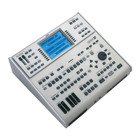
GEM promega 3 User manual

11
11
1
Index
Soldering point.
Male connector.
Female connector.
M/F faston connector.
Test point.
Supply voltage. Logic supply ground.
Analog supply ground.
Chassis ground.
Earth ground.
Flag joined with one or more flags
GENERALMUSIC S.p.A. Sales Division: 47842 S.Giovanni in Marignano (RN) ITALY - Via delle Rose, 12
Phone +39(0)541/959511 - Fax +39(0)541/957404 - Internet: www.generalmusic.com
Introduction, Checks & Adjustments.2
RS232 PC - RS422 MAC Cables.3
Block Diagram.
6
In/Out Board Schematic.
7Left Controls Panel Board Schematic.
8
Keyboard Interface & L/R Contact Board Schematics.
9Right Controls Panel Board (part2/2) & Lower Controls Panel Board Schematics.
10
Cpu & Sound Generator Board (part 2/2) Schematic.11
256+256Mb Dual Drake Sound Board (part 1/2) Schematic.12
Left & Lower Controls Panel PCB Layouts.
13
Right Controls Panel Board (part 1/2) Schematic.
14
Right Controls Panel & 256+256Mb Dual Drake Sound PCB Layouts.
15
Cpu & Sound Generator Board (part 1/2) Schematic.
4
Pot Motor Supply & Standby Board Schematic & Timing Table.5
In/Out, Pot Motor Supply & Standby & Keyboard Interface PCB Layouts.
256+256Mb Dual Drake Sound Board (part 2/2) Schematic.
16
17
Cpu & Sound Generator PCB Layout.18
Spare Part List.
19
with the same signal name inscribed.
ATTENTION
Observe precautions when handling electrostatic sensitive devices.
Notice
Service must be carried out by qualified personnel only. Any tampering carried out by unqualified personnel during the guarantee period
will forfeit the right to guarantee.
For a correct operation of the instrument, after having switched off, be careful to wait at least 3 seconds before switching on again.
To improve the device's specifications, the schematic diagrams may be subject to change without prior notice.
All components marked by this symbol have special safety characteristics, when replacing any of these components use only
manufacturer's specified parts.
The (µ) micro symbol of capacitance value is substituted by U.
The (
Ω
) omega symbol of resistance value is substituted by E.
The electrolytic capacitors are 25Vdc rated voltage unless otherwise specified.
All resistors are 1/8W unless otherwise specified.
All switches shown in the "OFF" position. All DC voltages measured to ground with a voltmeter 20KOhm/V.
✔
✔
✔
✔
✔
✔
✔
✔
✔
✔
✔
✔
✒
☎
®
SERVICE MANUAL
code 270278

22
22
2
INTRODUCTIONINTRODUCTION
INTRODUCTION
The Promega 3 is a complex instrument and to be repaired requires a detailed
knowledge especially on digital boards as 761257 - CPU & SOUNG GENERATOR BOARD
and 256+256Mb DUAL DRAKE SOUND BOARDs.
If you need to repair these parts by yourself we suggest to replace them entirely,
otherwise the following information can be useful to locate a specific problem.
FUNCTIONAL DESCRIPTIONFUNCTIONAL DESCRIPTION
FUNCTIONAL DESCRIPTION
The new keyboards 2000 series, of which PROMEGA 3 is the first keyboard developed
by GM, are designed around the new processor DRAKE (Dsp Risc Advanced Keyboard
Engine).
Inside PROMEGA3 5 DRAKE have assembled on, the first one on the main board and
the others are mounted on 2 sound boards.
The first DRAKE controls the general management, all the I/Os and the sound
processing (mixer and digital effects) while the others are used for sounds generation.
All sounds and operating system are stored inside NAND FLASH memories, the FLAH
memory content is decompressed and transferred in the SDRAM memories to allow fast
elaboration.
The decompression task requires about 1 minute, to avoid this time the SDRAMs have
been endowed of a battery supply circuit (+VBAT, +VBRAM); under normal conditions,
after 3/4 working hours, the batteries are completely re-charged and they allow the
data retention for over 1 week.
The numbers between parentheses are referred to the same points reported on the
schematic diagrams.
[1] MASTER RESET[1] MASTER RESET
[1] MASTER RESET[1] MASTER RESET
[1] MASTER RESET
Starting from the switch ON event the keyboard remains in reset condition; when the
5V supply rail reaches about 4.75V IC35 (MAX709) set high the VOK after 200mS,
which enters in the DRAKE pin 209; the RST is delayed of further 100uS respect VOK
and it goes in the DRAKE pin 161, it is synchronized to the PLL internally, goes out
through pin 213 and enters in pin 206 of the same DRAKE; besides it is also sent to the
same pins of each DRAKE connected by the SLOT BUS, in this way all DSP are
synchronized.
The RST is also sent to other ICs to initialize the I/O circuitry, see also the schematics
and timing table.
[2] MASTER CLOCK[2] MASTER CLOCK
[2] MASTER CLOCK[2] MASTER CLOCK
[2] MASTER CLOCK
The Master clock (MCLK) produced by the oscillator XT1 (11.2896MHz) is sent through
IC31 and IC26 (DS90 LVDS Low voltage differential signaling) to each DRAKE, DAC, ADC
and expansion SLOT. The LVDS receivers placed at each termination of the balanced
signal (REFCLK) are used to get a perfect synchronism between all the devices.
By means of IC25 (74lvc74) also the sample frequency FS (44.1KHz), deriving from
IC54 (ADCL/RCLK) or from a SLOT (EX_FS), is synchronized with MCLK.
[3] START UP SETTING[3] START UP SETTING
[3] START UP SETTING[3] START UP SETTING
[3] START UP SETTING
During the rising slope of RST, DRAKE configure
itself reading the state of address pins between
AD0...AD30-A and A0...A2-D, if the configuration
doesn’t match to a valid one, a malfunction could
happen.
Check these in the CPU and SOUND BOARD sche-
matics.
[4] BOOTSTRAP[4] BOOTSTRAP
[4] BOOTSTRAP[4] BOOTSTRAP
[4] BOOTSTRAP
The jumper J1 can be set on two positions:
UART = The DRAKE bootstrap happens from the
COMPUTER serial port.
E2 = The DRAKE bootstrap happens from the
eeprom device (IC15).
Initially, when the eeprom is empty, this jumper
must be set on UART, after the bootstrap is uploaded
into eeprom, the jumper J1 must be set to E2.
N.B. The 761257 spare parts already have the
bootstrap installed into eeprom.
[5] OPERATING SYSTEM & WAVE MEMORY[5] OPERATING SYSTEM & WAVE MEMORY
[5] OPERATING SYSTEM & WAVE MEMORY[5] OPERATING SYSTEM & WAVE MEMORY
[5] OPERATING SYSTEM & WAVE MEMORY
Often it happens that a malfunction of the instru-
ment is to investigate between the software rather
than the hardware.
Consequently it is necessary to know which Oper-
ating System (OS) version is loaded in the instru-
ment and eventually upgrade it with the last one
available; if the malfunction persists even if the
instrument is upgraded, please send a detailed
report to GM Italy.
The OS is contained in the NAND FLASH (IC7 and CN1) devices; these memories are
managed in similar way of a hard disk, for this reason GM supplies as spare part 761257
(CPU BOARD) including 761235 (NAND FLASH MODULE).
As discussed above to speed up the instrument OS and Waves are transferred on
SDRAM memory at the first startup, and are maintained on it by means of an internal
battery; till the battery is charged, or you does not force a restore as described further,
OS and waves are maintained on SDRAM.
To load for the first time or to upgrade with the last OS release, you need the
‘O.S.UPGRADE CD-ROM’ that is sent from GM upon request.
When you ask it please note your instrument serial number (SN#), it is written on the
label applied on the instrument backside, please also check the OS version and notify
both these information with the request.
To check the OS version proceed as follows:
Press the SPLIT P. button and, holding it down, press the “+” key at the side of the LCD:
on display appears the OS version number and date. Pressing again the “+” button the
display will show the filenames loaded into the instrument.
The OS version contained in the CD is specified by suffix in the filename (e.g.
Upgrade_PROMEGA3_v.1.01.exe); obviously, if the version installed on the instrument
is the same, the upgrade is not required.
IMPORTANT: When an instrument OS is upgraded, or when you want to restore the
initial manufacturer OS from NAND FLASH into SDRAM memories, you must press the
STANDBY button and, holding it down, turn on the instrument from the main
power switch. Firstly the display shows the result of the DRAM memory checksum
(WCKS OK or WCKS BD) secondly the state of the battery charge (BATT OK Or BATT
BD), where OK means good and BD means BAD; then the instrument will continue
forcing the decompression in the DRAM that requires about 1 min.; finally 5 OK will be
visualized to confirm the correct memorization on the SDRAMs of each DRAKE.
[6] RAM BACKUP & POT’S MOTORS SUPPLY RAIL[6] RAM BACKUP & POT’S MOTORS SUPPLY RAIL
[6] RAM BACKUP & POT’S MOTORS SUPPLY RAIL[6] RAM BACKUP & POT’S MOTORS SUPPLY RAIL
[6] RAM BACKUP & POT’S MOTORS SUPPLY RAIL
The board 731050-POT MOTOR SUPPLY & STAND-BY BOARD handles the supply rail of
the motorized potentiometers and, at the same time, the battery recharge; however
the 731011 - SWITCHING SUPPLY UNIT doesn’t have enough current for both circuit
simultaneously, two current limiters are connected in series (TR2, TR5 and TR3, TR4),
that privilege the motors supply (IC4) on request instead the recharging of the battery
(IC2).
IC1 inhibit the complete discharge of the batteries to extend their life, IC3 stabilizes
the 3.3V supply rail for the SDRAMs and TR1, by means of an impulse from the CPU,
handles to re-start the recharge circuitry every around 15min. and each time that the
state of the batteries charge is checked by CPU.
[7] SOUND BOARD (SLOT), PEDALS, AU-[7] SOUND BOARD (SLOT), PEDALS, AU-
[7] SOUND BOARD (SLOT), PEDALS, AU-[7] SOUND BOARD (SLOT), PEDALS, AU-
[7] SOUND BOARD (SLOT), PEDALS, AU-
DIO, PANEL checks using TESTMON tool.DIO, PANEL checks using TESTMON tool.
DIO, PANEL checks using TESTMON tool.
To perform these tests you must have a PC (Windows
95 or more) and the TESTMON program with the
follows precautions:
• A suitable serial cable (GM code 130429) is re-
quired.
• A suitable hardware (not provided) is necessary,
see schematic figures 1 and 2.
• A complete re-loading of OS is necessary after
using this program.
• The TESTMON program can be request to GM Italy
only.
• The TESTMON program must be used only in the
form specified here, other functional test without
the suitable hardware (not provided) could com-
promise the CPU BOARD.
Proceed as follows:
1) Connect the PC serial port COMx to the instrument
COMPUTER port by means of the suitable cable.
Both apparatus must be switched OFF.
2) Turn on the PC install and run the TESTMOM
program, the following window appears on PC
screen:
3) Set the right COMx through the
“Test/Serial port” menu.
4) Turn on the instrument and the
test will start automatically visu-
alizing:
Name of test and current date:
________________ Test 4, today, time ________________
The sound modules first test will start:
- [9] Testing Ext. Modules (CN2, 6, 7, 8) :
Test result:
————————————— SCREENING —————————————
Chip_0 (IC4) Chip_1 (IC19)
Slot_0 (CN8) No No
Slot_1 (CN7) Yes Yes
Slot_2 (CN6) Yes Yes
Slot_3 (CN2) No No
Testing VOK —> OK
Testing BID —> OK
- Pass!
The pedal inputs second test will start:
- [11] Testing Pedal Inputs :
Test result:
- Pass!
The audio I/O third test will start:
- [12] Testing Audio Loop :
Verify that AUX OUT signals respect the specifications.
Verify, using an oscilloscope, that a sinusoidal signal of about 5Vpp is present on every
output.
The controls panel fourth test will start:
- [20] Testing Panel :
Use the controls on the instrument to perform the test
and verify on the display the reading values.
The panel test doesn’t send messages on this window, with
the exception of last test that signals the end of all
test.
Press STAND-BY to advance the test of a step:
- Step 1/15 lights on all the leds of the panel.
- Step 2/15 lights off all the leds of the panel.
- Steps 3/15 to 12/15 the digits vary from 0 to 9 and a led couple of each encoder flows.
- Step 13/15 the digits return to 0 and the display shows:
“Pi =... Mo =... Vo =... In =...”
Operating the Pitch, Modulation, Volume and Input controls from minimum to maximum
excursion verify that the reading values vary accordingly from 0 to 127.
Pressing each button on the panel the correspondent led lights on or causes a variation
on the nearest digits and finally that rotating the encoders, the leds of the correspond-
ing wheel light on in the same sense of rotation.
- Step 14/15 the display shows:
“AT =... Ct =... PC =...”;
Pressing the note keys beyond the end stroke the aftertouch value (AT) varies from a
minimum of 0 to a maximum of 127.
N.B. it is possible to set the AT by means of VR1 on the CPU BOARD, with the purpose
to get the optimum variation with the wishes pressure, in any case this setting always
remains subjective for 2 reasons: the first one is that being the strip in conductive
rubber the same one for all the keys, you can feel notably changes if a single note or
an accord is pressed, besides in the PROMEGA 3 the preset sounds that make possible
to set the AT are BRASS1 and BRASS2.
- Step 15/15 verifies the uniform motion of the motorized potentiometers.
- *********** TEST PASSED ***********
End of the test, switch off and on again the instrument.
Bit Bus Si
g
nal Resistor Initial State
0D16R391
1D17R450
2A2R230
3A3R280
4A4R240
5A5R250
6A6R260
7A7R270
8A8R351
9A9R401
10 A10 AR22 0
11 A11 AR22 1
12 A12 AR22 0
13 A13 AR22 0
14 D18 R37 1
15 D19 R78 1
16 D20 R38 0
17 D21 AR45 0
18 D22 AR45 0
19 D23 AR45 0
20 D24 R52 0
21 D25 R59 0
22 D26 R51 1
23 D27 R65 0
24 D28 R67 0
25 D29 R68 0
26 D30 AR45 0
27 DD16 AR37 0
28 DD17 AR37 1
29 DSPA2 AR37 0
30 DSPA3 AR37 0
* this chart is referred to 761257 only,
for 761229 refer to schematic only.

33
33
3
[8] Pitch and Modulation Adjustment procedure:[8] Pitch and Modulation Adjustment procedure:
[8] Pitch and Modulation Adjustment procedure:[8] Pitch and Modulation Adjustment procedure:
[8] Pitch and Modulation Adjustment procedure:
If, during point 7 test, one of the Pitch or Modulation
wheels doesn’t sweep its entire range from 0 to 127, or
with the Pitch centered it doesn’t position between 63
and 65, you must execute again the Pitch and Modula-
tion adjustments as follows:
a) Make sure that the potentiometer is positioned as in
figure and well fastened to the plastic loom.
b) Connect a good stabilized continuous voltage of 5V
(±5mV) between 1 and 3 or 4 and 6 pins of
connector, connect the multimeter at pin 2 or 5
according to the wheel that you are regulating.
c) Extract the wheel, rotate the potentiometer shaft up
to read around 2.5V on the multimeter, re-insert the
wheel centered as in figure.
d) Keeping still the wheel centered and using a spanner
on nuts R or S each potentiometer will rotate jointly
with the respective nut; rotate it till to have a voltage
of 2.5V±25mV at pin 2 and 5 of connector.
e) Rotating the PITCH wheel all along its excursion,
verify that the voltage starts from a minimum less
than 250mV to a maximum higher than 4.75V.
f) Rotating the MODULATION wheel all along its excur-
sion, verify that the voltage starts from a minimum
less than 25mV to a maximum higher than 4.75V.
g) If the point “e” or “f” is not verified repeat the
adjustment.
[9] MIDI and Computer ports check[9] MIDI and Computer ports check
[9] MIDI and Computer ports check[9] MIDI and Computer ports check
[9] MIDI and Computer ports check
Press LOCAL OFF, the keyboard doesn’t play anymore but continues to send the MIDI
signal through channel 1, connecting with a suitable cable MIDI IN and MIDI OUT ports,
the keyboard plays (section PIANO=CH1); disconnecting the cable the keyboard
doesn’t play again, inserting an RS232 loopback plug (pin 1-2 and 3-5 shorted) in the
Computer port the keyboard plays again.
Check that it works well also setting PC1 or PC2 modes and when in MAC mode goes
out from pin 1 a 1MHz signal.
[10] Pedals check[10] Pedals check
[10] Pedals check[10] Pedals check
[10] Pedals check
Even if in the point 7 the pedal inputs have been already checked, due to their particular
effects it’s a good idea to give an ulterior explanation about them:
All three inputs are analog and they accept pedals normally closed as such normally
open, as well as potentiometer pedals.
The kind of pedal is recognized at the power on or when it is plugged in.
In the PROMEGA 3 the pedals by default are assigned in Grand Piano mode:
• PEDAL1 (left) = SOFT,
• PEDAL2 (central) = SUSTAIN,
• DAMPER (right) = DAMPER.
In practice they act in the following way:
SOFT = it attenuates the notes simulating the moving away of all hammers,
SUSTAIN = it holds up the dampers of the notes pressed simultaneously to the pedal,
if it remains pressed the notes previously pressed maintain the sustained effect, when
the pedal is released the notes are not sustained anymore.
DAMPER = it holds up the dampers of the whole keyboard and activates the
sympathetic resonance of strings near to the pressed notes, in practice an enrichment
of the sound on the decadence of the pressed notes is the audible effect.
If a potentiometer pedal is inserted it is possible to simulate also the intermediary
damper positions.
Simulating the sympathetic resonance like a real Grand Piano, the notes upper to MI6
(E6) have the effect always audible due to these have not the dampers, at the same
time the pedal effect is more audible in the highest notes, to check it press a note close
to MI6 (E6).
Modulation
R S
ORANGE
RED
RED
BROWN
BLACK
BLACK
1
min
max
centre
Pitch
1

44
44
4

55
55
5

66
66
6

77
77
7

88
88
8

99
99
9

1010
1010
10

1111
1111
11

1212
1212
12

1313
1313
13

1414
1414
14

1515
1515
15
S11
C66
S13
R112
R111
RL3
CN3
C63
C72
C54 R78
R76
R90
L5
L6
C53
R101
R93
L24
L27
R9
R10
C21
S9
R11
R12
C68
RL2
C67
CN1
CN4
C60
CN2
R36
S5
S1 S10
S3 S4
S8
S7
S6
S12
S14
IC9
C6
C37
C7
C40
C1
C2
C3
C4
R17 R21
M1
M0
L1
L2
R1
R2
R3
R4
L3
L4
R5
R6
R7
R8
S2
C5
R19
L14
L15
L16
L17
L18
L19
R49
R48
R41
C33
IC4
L21
L22
L23
L29
L28
D6
RL1
R52
C61
R94
TR1
R88
L25
R95
R89
C18
R91
R92
R53
R54
C16
R55
R56
C38
R57
R58
C43
IC6
C41
R59
R60
R62
R63
R61
R64
C44
C17
C42
C39
C35
TR4
R50
R51
TR3
C32
C31
R115
C75
R100
C45
R75
R73
R74
L20
C22
C36
C24
C15
R66
R65
C46
R67
IC2
R69
C47
IC7
C48 C49
C51 IC8 C57
R87
R86
R84
R82
R70
IC1
R13
R15
R46
R43
R44
R25
R42
D5
IC3
R37 R40
R99
C71 R110
R109
C76
C70
R116
R117
R98
R113
C52 C56
R26
C30
C29
R47
C34
R72
C50 R79
C55
SW1
VR1
C23
R28 R30
L13L12L11L10
L9
L7
R20
C8
C14
C12
C11
C10
R14
L8
C9
R18
C13
R68
R71
R81
L26
R107R108
R114
R96
R77
R80
IC10
C65
C64
C62 R97
R102
R103
C69
R104
R105
R106 C73
C58
C59
R83
R85
R16
TR2
R24
C19
C20
R27
D1
R33
D2
D3
D4
C27
R34
R39
R38
R32
R22
R23
C74
C25
R29
J1
R31
C26
C28
R35
R45
XT1
IC5
C8
R21
R27
IC4
C11
R22
C10
C17
TR3
TR4
C16
D6
TR2
R25
TR5
CN3
D7
R17
C18 C19
R13
R26
C20
IC3
C6 C7
R24
CN1
R23
R20
R16
R19
M0
R4 R5
IC1
C2
C15
TR1 R15
R18
DL1
C14
C12
R10
CN2
C13
R8
D3D2
C3
R6 R7
C1
R1
R3
R2
IC2 M1
R14
R12
C9
R11
C4
D1
D4 D5
D8
R9
C5
HS1 HS2
R3
C7
R4
C8
R5
C9
R6
CN2
AR5
C3
IC2
D1
R8
C10
C11
R9
R10
R7
IC5
C6
AR1
AR4
IC3 C5
AR3
C4
AR6
IC4
IC1
AR2
R2
R1
C2
C1
M1
M0
CN1
CN5
CN6
CN8
CN7
CN4
CN3
R11
C12
TR2
TR1
C13
731043 - IN/OUT BOARD
731050 - POT MOTOR SUPPLY & STAND-BY BOARD 761226 - KEYBOARD INTERFACE BOARD
DWG#
CKD
APP.
DRW
REV:
DATE:
GENERALMUSIC S.p.A. ITALY
ALL RIGHTS ARE RESERVED, NO COPIES
OR REPRODUCE THIS DOCUMENT WITHOUT
WRITTEN CONSENT BY GENERALMUSIC.
PCB#
M.GALANTI
M.GALANTI
G.BOCCATO 310688 / 310678 / 310697
22/04/02
A
500964
PCB Silkscreens of:
POT MOTOR SUPPLY & STAND-BY BOARD; KEYBOARD
INTERFACE BOARD; IN/OUT BOARD.

1616
1616
16
DWG#
CKD
APP.
DRW
REV:
DATE:
GENERALMUSIC S.p.A. ITALY
ALL RIGHTS ARE RESERVED, NO COPIES
OR REPRODUCE THIS DOCUMENT WITHOUT
WRITTEN CONSENT BY GENERALMUSIC.
PCB#
M.GALANTI
M.GALANTI
G.BOCCATO 310682 / 310698 / 310687
24/04/02
A
500965
PCB Silkscreens of:
LEFT CONTROLS PANEL BOARD
LOWER CONTROLS PANEL BOARD
M1
C16
DL26
C34
DL27
DL28
DL29
DL30
DL31
DL32
DL33
DL23
DL34
DL9
DL52
DL53
DL54
DL55
DL56
DL57
DL58
DL59
DL60
DL61
DL62
DL63
R53
DL64
DL65
C39
DL51
R55
C31
DL24
SW19
VR5
R56
R54
DL71
DL73
DL72
C17
DL74
DL4
DL68
VR6
C40
VR3 VR4
C30
C52
DL10
SW20
C14
C15
C18
C32
C33
DL11
DL35
SW10
SW9
DL5
C42
DL12
SW11 SW12
SW13 SW14
SW7
SW8
DL13
SW15 SW16
C53
C19
DL14
C41 C54
C7
C8
C9
C12
SW18
DL8
DL40
C10 C11 C13
DL42
DL69 DL70
DL41
DL43
DL50
DL66
DL36
DL67
C56
DL15
C60 C65
SW17
IC7
DL16
DL37
DL38
DL39
R178
DL17
R179
DL25
DL18
DL19
DL20
CN6
SW1 SW2
SW3
DL21
DL22
SW4
SW5
CN7
SW6
IC22
R148
R147
IC26
IC27
IC21
CN2 CN3 CN4
IC32IC30
R158
R159
R160
R161
R162
R163R164
R165
IC28
R180
R183
R184
R185
R186
R181
R172
R173R174
R175
R190 R191
C64
R121
C37
R166
R167R168
R169
R64
R62
R66
R59
R61
R63
R65 IC9
R60
R58
R57
IC8
IC13 IC12
IC10
IC11
R89
R95
R83
R101
IC17
R99
R93
R87
R81 R79
R97
R91
R85
IC15
R96
R78
R84
R90
IC16
R80
R86
R92
R98
R82
R88
R94
R100
R108
R119
IC18
IC20
R106
R118
R112
R117
R111
R107
IC19
R102
R103
R104
R105 R116
R113
R115
R114
IC23
IC24
R142
R141 R140
R139
IC25
R151
R143
R144
R145
R146
IC33
R135
R136
R137
R134
R150
R149
R152
DL44 DL45 DL46
DL47 DL48
DL49
CN1
M0
R124
CN8
R182
R192
C24
IC14
C20
R73
C27
C23
C22
C21
R68
R69
R70
R67
R75 C29
R74
C28
R72
C26
R71 C25
C47
R131
C48
R129
C49
R130
C50
R133
R138
R195
R196
R187
R189
R188
R199
R198
R197
C36
R120
R126
C44
R127
C43
R153 R154
R155
R156
C55
R157
CN5
C45 C51
C46
L1
R109 R110
R123
R125
C38
R122
R52
C68
C35
R132
C57
IC29
C59
R171
C58
R170
C63
R177
C62
R176
C61
IC31
C66
C67
R194
R193
J1 J2
DL6 DL7
R76
R77
R128
SW23
SW21
SW22
R2
R50
R19
R5
IC1
R3
R1
C1
IC2
R13
R11
R9
R7
R18
R17
R15
C2 C3
R35
R27
R25
IC3
R23
R21
R34
IC4
R33
R29
R31
C4
R43
IC5
R41
R39
R37
R51
IC6
R49
R47
R45
C5 C6
DL25
R19
R17
R20
R5
R8
C1
DL23
C3
IC1
R1
DL26
DL3 DL4 DL21DL20
DL1 DL2 DL8 DL9DL7DL6 DL14 DL15 DL16 DL17 DL22 DL24
DL19DL18DL13DL12DL11DL10
DL5
SW19
SW10
IC2
LCD1
SW5
SW6 SW7
SW26
SW8 SW9
SW11
SW14 SW15 SW16 SW17 SW22 SW24
SW1 SW2
SW12
SW13
SW3 SW18
SW4
SW25
SW20
SW21 SW23
C19
M0
M1
C26 C29
C15
C8
C27 C28
R3
C18
C17
C10
R9
C12
C7
R18
R32
R15
C16
TR1
R69
R66
IC11
IC14
R71
R68
IC6
R26
R25
R23
R24
R63
R60
R59
R58
R81
R80
R73
R72
R79
R78
R87
IC3
R12
R2
IC12
R61 R64
R62 R65
R70R67
IC13
R83
R84
R85
R86
R74
R75
R76
R77
R14
R4
R22
R21 R27 R29
R28 R30
IC5
R7
R55
R56
R57
R54
IC10
R48
R49
R47
R46
C25
R11
R35
C5
C6
R6
R82
C30
IC15
C34
R92
C36
R98 C40
R95
R96
R93
C37
C39
C38
R88
R91
C33
C35
R94
C32
R97
C24 IC9
R52
R50
R51 R53
R44
R45
R42
R43
R10
R89
CN3
CN2 IC7
C20
R31
IC8
R38 R39
R40
R34
C21
R33
R36
C22
C23
R41 R37
C9
D1
C4
CN1
C13
R90
C31
IC4
R13C11
C14
C2
R16
810688 - LEFT CONTROLS PANEL BOARD
810694 - LOWER CONTROLS PANEL BOARD

1717
1717
17
DWG#
CKD
APP.
DRW
REV:
DATE:
GENERALMUSIC S.p.A. ITALY
ALL RIGHTS ARE RESERVED, NO COPIES
OR REPRODUCE THIS DOCUMENT WITHOUT
WRITTEN CONSENT BY GENERALMUSIC.
PCB#
M.GALANTI
M.GALANTI
G.BOCCATO 315179 / 310683
24/04/02
A
500966
PCB Silkscreens of:
RIGHT CONTROLS PANEL BOARD;
256+256Mbit DUAL DRAKE SOUND BOARD
R181
R180
DL40
R179
R178
SW23
R188
R187
C77
IC29
C28
C41
C54
R186
R185
R184
R183
R182
R177
C62
R56
CN4
R55
C64
DL75
CN5
DL74
R284
R283
R57
R58
DL41
SW22
DL73
R282
R281
R59
SW20
DL71
R60
DL69
DL72
DL70
DL18
R310
DL19 DL20 DL42
R309
SW24
DL43
R308
R307
SW21
DL44 DL66 DL67 DL68
R306
R350
M1
R118
C58
R349
R348
R347
R346
R345
R344
R342
R343
R341
R340
R176 R243
R339
R338
R337
R336
R335
R242
R334
R333
R241
R240
R239
R238
R237
SW3
R260
R236
R235
R279
R278
R277
R276
R267
R275
R274
R273
R272
R271
R270
R269
R268
R266
R265
R264
R263
R262
R261
R175
R174
R173
R172
R171
R170
R169
R168
R301
R280 R353
R352
R351
R326R255
DL24
SW14
DL17
DL22
DL16
SW2
SW12
SW13
SW6
SW4
DL48
SW7
SW11
SW17
DL23
DL21 DL46
SW5
SW16
SW10
SW18
SW9
DL47
DL45
DL64
DL65
SW19
DL4
DL5
DL6
DL7
DL8
DL9
R161
DL10
DL11
DL12
DL13
DL14
DL15
DL1
DL2
DL3
DL28
DL29
DL30
DL31
DL32
DL33
DL34
DL35
DL36
DL37
DL38
DL39
DL25
DL26
DL27
DL52
DL53
DL54
DL55
DL56
DL57
DL58
DL59
DL60
DL61
DL62
DL63
DL49
DL50
DL51
DL80
DL79
DL81
DL76
DL77
DL78
DL83 DL86 DL89 DL92 DL95 DL98
DL84 DL87 DL90 DL93 DL96
DL82 DL85 DL88 DL91 DL94 DL97
DL99
IC13
IC14
IC17 IC20
R90
IC16
R165
R164
R166
R160
C59
R119
R70
C60
C61
R78
R79
R72
R80
R82
R85 R84 R83
C46
R81
R88 R87 R86
R101 R100 R99 R89
R106 R104 R103 R102
R117
R116
R115
R105
R63
R50
R51
R52
R54
R40
R42
R43
R44
R37
R38
R39
R41
R16
R18
R19
R20
R14
R15
R13
IC6 IC11
IC8
R17
R53
R61
R62
IC24 IC25 IC28
R121
R123
R122
R125 R128
R127
R126
R124
R133
R131 R130
R129
R144
R143
R142
R132
R149
R147
R146
R145
R159
R158
R157
R148
IC23
C17
IC22
R254
R253
R252
C21
R251
R36
R250
R249
R248
R209
R208
R207
R206
R205
R204
R203
R202
R201
R200
R199
R198
R197
R196
R195
R194
R193
R192
R191
R190
R189
R223
R163
R221
R222
R230
R229
R228
R227
R226
R225
R224
R247
R246
R220
R219
R218
R217
R216
R215
R214
R213
R212
R211
R210
R245
R244
R300
R299
R298
R297
R296
R295
R294
R293
R292
R291
R290
R289
R288
R287
R286
R285
R325
R324
R323
R322
R321
R320
R319
R318
R317
R316
R315
R314
R313
R312
R311
IC41
IC15
R68
R69
R71 C56
R75
R76
R74
R73
IC9
IC26
IC44
IC33
IC52
IC31 IC35 IC37 IC42IC39
IC32 IC34 IC36 IC38 IC40 IC43 IC45
IC46 IC51
IC47 IC49
IC48 IC53
IC2
R1
C66 C68 C70 C72 C75
C30
C79 C81 C84
C38
C47
C39
C48
C2
C40
C29
C32
C43
C50
C51
C49
C45
C35
C42
IC10
C44
R91
R92
R93
R94
R23
C52 C73 C82
R77
R120
R256
R167
R259
IC19
R112
R111
R46
R47
R48
R49
R98
R97
R96
R95
R114
R113
IC18
R110
R109
R108
R107
IC27
R154
R155
R156
R138
R139
R140
R141
R150
R151
R152
R135
M0 R258
R257
R234
R233
IC50
R304
R305
R303
R302
R331
R330
R328
R327
IC12 IC21
R136
R137
R134
C25 C53 C63 C65 C67 C69 C71 C74 C76 C78
C27 C80 C83
C1
SW8 SW15
SW25 SW26 SW27 SW28 SW29 SW30 SW31 SW32
SW1
CN1 CN3
CN2
R29
C3
C8
R153
R30
C13
C37
C18
R25
IC30
C57
R162
C55
L1
R232
C36
C33
C31
C34
R67
R66R64
R65
R4
IC7
C26
R26
IC1
C19
R10
R9
R11
R12 IC3
R28
R27
IC5
C11
R7
R8
C9 C12
C7
R6
R5
C6
IC4
C10
C16
R35
C15
R34
R33
R32
C14
C24
C23
R22
R21
C22
R2
C4
R31
C20
R3
C5
R231
VR7 VR8 VR9
R329 R332
R24 R45
CN5
IC14
R100
C58
C47 IC11 IC8
D3
IC7
C57
IC6
AR18
AR8
AR13
AR17
AR26
AR1
R45
MB1
C8
C6
C12 C10
MB0
AR20
IC3
IC17
R13
R8
R6
R93
IC20
IC5
IC21
R4
C9
R101
C13
R29
R11
R70
R71
R72
R73
C3
IC18
C56
C14
C53
C23
R16
R31
C27
R43
R38
R36
R35
R34
R37
R17 R7
R75
R61
R60
R59
C15
C18
R41
C36
C37
C54
C52
C51
C59
C50
C61
C60
C21
C22
AR12
R23
C11
C17
R2
R3
IC2
R47
C2
C1
R9
R19
R20
R10
C67
AR2
R55
R58
C42
R92
R39
C55
C19
R40
R74
R91
R90
R98
R99
C65
C16
R105
C68
R94
R95
R46
TR3
C20
CN1
C26
C43
IC15
IC13
TR2 IC16
R64
IC12
IC1
AR24AR22
AR34
AR21
AR14AR11
CN5
R89
CN2
R83
TR1
CN3
D2
IC4
J4
AR19 AR23
AR10
AR3 R66
AR29
AR9
R65
M1
AR28
J3
R1
AR5
AR16
AR15
C64
C31
R69
R67
AR6
AR7 AR4
AR31AR30 AR32
IC10
IC9
C40
C41
M0
IC19
R50
R85
R49
R87
C4
R12
C63
R33
C34
C35
R62
R5
R103
R82
C32
C29
R44
C49
C46
C62
C45
C24
C66
C7
C30
C28
C5
R102
R28
R14
R18
R22
R25
R15
R21
R24
R26
R27
AR25
TR5
C38
R51
R54
R53
R52
C39
C33
C44
R63
R76
R77
R78
R79
R80
R81
R84
R86
R88
AR33
C48
C25
R42 D1
D4
R68
R32
R30
R104
AR27
R97
R96
CN4
R48
TP1
TP2
810689 - RIGHT CONTROLS PANEL BOARD
761229 - 256+256Mbit DUAL DRAKE SOUND BOARD (SIDE A) 761229 - 256+256Mbit DUAL DRAKE SOUND BOARD (SIDE B)

1818
1818
18
DWG#
CKD
APP.
DRW
REV:
DATE:
GENERALMUSIC S.p.A. ITALY
ALL RIGHTS ARE RESERVED, NO COPIES
OR REPRODUCE THIS DOCUMENT WITHOUT
WRITTEN CONSENT BY GENERALMUSIC.
PCB#
M.GALANTI
M.GALANTI
G.BOCCATO 310171
23/04/02
A
500967
PCB Silkscreens of:
CPU & SOUND GENERATOR BOARD
IC48
R79 R83
R61
C137
C99
C55
C94
R8
IC44
R35
IC32
C17
R33
C11
C2
IC50
AR27
R106
R215
R57
R223
C78
CN15
J3
R149
R11
R190
R144
R163
C109
R199
R119
R80
C95
R141
AR23
AR70
C3
C89
C111
IC24
R82
R46
IC33
R114
IC20
AR19
R189
R227
R105
R97
C42
R42
AR53
AR52
R103
R195
R75
C1
C52
R12
AR71
AR26
R66
R51
R146
C20
IC2
R73
C45
C16
R188
C41
C25
R193
C31
C49
C9
C18
R142 J2
R216
C138
C39
AR51
AR46
R108
C10
C96
C131
R67
R84
C125
C71
R197
AR59
R104
R196
C100
R62
R49
R100
C60
C12
IC25
R166
C59
C14
R145
C126
AR47
R157
R204
C43
R203
C110
C87
C139
C15
R222
R3
R76
IC26
IC31
R18
C13
AR78
AR79
C40
C150
IC27
R45
CN12
R202
CN13
R74
R231
R39
R201
R200
IC51
R20
C141
C143
R205
R210
C29
IC47
R206
AR54
R95
AR55
C103
C44
C8
C7
CN4
CN5
R64
R150
R101
C22
C33
XT1
R58
AR48
IC28
C35
IC49
IC34
R207
R208
CN11
AR95
IC30
IC6
IC41
R187
R191
C123
CN16
IC10
IC40
C21
IC1
R214
IC11
IC14
IC19
IC18
R6
C26
IC22
CN6
CN7
CN8
CN2
IC12
C58 C36
IC56
IC55
C47 C57
C97
IC42
C98
IC43
C91
R211
IC45
IC8
IC46
C101
R158
R147
R159
R68
IC13
IC16 IC17
R16
R19
R168
IC9
R175
R209
R226
R29
R10
R50
R17
R52
R59
IC29
R63
R65
AR104AR103
AR105
AR94
AR61
AR93
C6
AR62
IC23
AR15
AR18
IC15
M1
AR17
AR14
AR69
AR68
AR64
AR38
AR20
AR21
AR85
AR87
AR84
AR86 AR88 AR89 AR90
AR91
AR60
AR56
AR10
AR11
AR12
AR9
AR44
AR74
AR100
AR40AR39
AR75
AR76
AR63
AR65
AR43
AR37
AR7
AR80
AR81
AR102
AR82
AR83
AR22
AR92
AR4 AR5 AR6 AR8
AR16
AR41
AR45
AR42
IC3
R7
C5
IC5
AR35
AR36
AR34
AR31
R4
AR13
C4
IC4
AR25
AR24
C19
R27
R32
R26 R31
R25
R30
R24 R28
R23
R22
AR29
AR33
AR32
AR30
AR28
R48
R47
R40
CN1
AR1 AR2 AR3
R9
AR73
AR72
R15
D2
R34
R44
R43
R41
R36
AR57
R72
R71
R86
C37
IC21 AR77
R85
R93 R94
R117
R118
C80
C108 IC39
IC38
C27
C23
R37
R38
R162
R148
R161R160
C93
R112 R116
J1
C24
AR67AR66
R115
C90
C146R224C144
R21
D5
C107
R156
R217
C115
C114
C112
C104
D6
IC54
R140
C84
C117
C122
C116
IC37
R151
IC53
C79
R132
C76
R133
R134
R135
R136
R137
R138
C81
R143
C145 R225
VR1
AR101
AR99
AR96
AR97
AR98
IC35
R164
R165
C56
C105
R152
R153 R154
R155
C120C119 C124
C121
R176
R219
R218
C113
R177
R220
C75
C65
C67
C66
R125
R124
R131
R123
C69
IC36
R129
C68
C63
R128
R127
R126
C62
R130
C77
R122
C64
IC52
C61
C50
R88
R87
XT2
R5
C32
C70
C73
C74
R139
R121
R107
R53
R54
R55
R56
R78
R77 D4D3
C88
C86
R120
CN10
CN3
C38
R13
R99
R98
R69
R169 R173
R174
R170 R172
R171
C48
R1
R194
C132
C133
C134
C135
C136
C130
IC7
C129
C128
R183
R182
R181
R180
R179
R178
R186
R185
R184
R192
CN9
CN17
CN20
CN14
CN18
CN19
C46
R212
R213
C127
C118
R221
R198
R167
R81
R92
R91
R90
C140
C142
R111
R109
D1
R2
R89
C34
R102
C106
C72
C102
C82
C51
C53
C147
R230
R228
R96
R229
C149
C148
M0
C83
C85
C54
R113
R60
R70
AR49
AR50C28
C30
AR58
R233
R14
C92
R232
R110
E
2
UART
1
1
315171 CPU BOARD
761257 - CPU & SOUND GENERATOR BOARD

1919
1919
19
Spare Part ListSpare Part List
Spare Part List
Code Description
Legend
US = Specify US Version
EU = Specify EU Version
Optional AccessoriesOptional Accessories
Optional Accessories
970418 Piano Triple Pedal (Dual Foot Switch + Damper)
130301 2mt Midi Cable
AccessoriesAccessories
Accessories
970134 Piano Single Foot Switch
271343 Owner's Manual
130283 Mains Cable (US)
130274 Mains Cable (EU)
Top AssemblyTop Assembly
Top Assembly
660738 Top Panel Chassis
653536 "b-#" Dual Actuator
653534 "ON/OFF" Single Actuator
653533 "RESET" Single Actuator
653532 "SPLIT P." Single Actuator
653531 "< >" Dual Actuator
653530 "TOUCH" Single Actuator
653529 "LOCAL OFF" Single Actuator
653528 "PRESET" Single Actuator
653527 "STORE" Single Actuator
653526 "LOCK" Single Actuator
653525 "TO LEFT" Single Actuator
653524 "CONTR." Single Actuator
653523 "5-6-7-8" Quad Actuator
653522 "1-2-3-4" Quad Actuator
653521 "- +" Dual Actuator
653520 "REVERB-PRO EFX" Dual Actuator
653519 "PARAM2-SEND" Dual Actuator
653518 "DEPTH-PARAM1" Dual Actuator
653517 "TIME-SEND" Dual Actuator
653516 "DEPTH-DELAY" Dual Actuator
653515 "SOUNDS-MIDI" Dual Actuator
653513 "DEMO" Single Actuator
653512 "USER" Single Actuator
653511 "E-F-G-H" Quad Actuator
653510 "A-B-C-D" Quad Actuator
651927 Plexiglass Bargraph Screen
651648 Plexiglass Lcd Display Screen
347409 Dark Gray/Red Slider Knob
341024 Black Knob
340986 D=3.3mm H=9mm Spacer for Metal Panel
340984 Slider Antidust Cover
340982 Plexiglass Green Display Screen
340978 Slider Frame
340976 Plexiglass Red Display Screen
340973 Plexiglass Encoder Led Screen
340426 D=7.5 H=13 Plastic Ferrule for Pitch/Mod Group
340186 Adhesive Cable Fixing
340115 Adhesive Flat Cable Fixing
210020 1.5x12mm Adhesive Red Felt (specify mt)
210017 2x10mm Adhesive Black Felt (specify mt)
210016 1x10mm Adhesive Black Felt (specify mt)
120581 M3 Black Self-Locking Nut
Right Control AssemblyRight Control Assembly
Right Control Assembly
810698 Right Control Assembly
810689 * Right Controls Panel Board (Pcb#310683)
340971 ** Encoder Led Support
340091 ** 4mm Led Spacer
230569 ** FL5R200PNT EMI Coil For Signal
141101 ** 4 Contacts Vert Male Connector
140953 ** 6 Contacts P=2.54mm Female Vert Strip
140910 ** 14 Contacts Vert Male Connector
140529 ** Microswitch 12V 50mA 0.25mm
110262 ** Dial Encoder with 15 Snap H=20mm Alps
103032 ** 74HC165D SOIC 8bit P To S Shift Register
103028 ** 74HC4094M1R SOIC 8bit Shift/Latch Register
103017 ** 74HC4051DW SOIC 8ch Analog Multiplexer
103000 ** 74HC14D Soic Hex Inverter Schmitt Trigger
100963 ** BA6218 SIP Reversible-motor Driver
080760 ** SA05-11EWA Kingb. 7 Segments Red Display
080759 ** 2x5mm Rect Diffused Green Led
080758 ** 2x5mm Rect Diffused Red Led
080736 ** DC-10EWA Kingb. 10 Elements Red Led Bar
080723 ** 3mm 40deg High Eff Red Led
055048 ** 10K 1/16w 5% Smd Resistor 0603
055032 ** 470E 1/16w 5% Smd Resistor 0603
055028 ** 220E 1/16w 5% Smd Resistor 0603
055024 ** 100E 1/16w 5% Smd Resistor 0603
031007 ** 10u 16V 20% Smd Electrolytic Tantalium Capacitor
011260 ** 100n 16V 10% Cer. Cap. Smd CL2 X7R 0603
011224 ** 100p 16V 10% Cer. Cap. Smd CL2 X7R 0603
731042 * Motorized Pot Board (Pcb#310689)
140956 ** 40 Contacts P=2.54mm H=8.5mm Male Vert Strip
130063 ** AWG24 Red Cable
130061 ** AWG24 Black Cable
072001 ** 10KB 60mm Motor Slider Pot. Shaft H=7.1mm
120028 * M3x6tc Black Screw
Left Control AssemblyLeft Control Assembly
Left Control Assembly
810697 Left Control Assembly
810688 * Left Controls Panel Board (Pcb#310682)
731049 ** 3 Digit Display Board (Pcb#310698)
103028 *** 74HC4094M1R SOIC 8bit Shift/Latch Register
080761 *** PSA05-12GWA Kingb. 16 Segments Green Display
055032 *** 470E 1/16w 5% Smd Resistor 0603
011060 *** 100n 50V 10% Cer. Cap. Smd CL2 Y5V 0805
340971 ** Encoder Led Support
340091 ** 4mm Led Spacer
230569 ** FL5R200PNT EMI Coil For Signal
141101 ** 4 Contacts Vert Male Connector
140953 ** 6 Contacts P=2.54mm Female Vert Strip
140935 ** 6 Contacts Hor Male Connector
140910 ** 14 Contacts Vert Male Connector
140874 ** Single In Line Vert Male Strip (specify contacts)
140529 ** Microswitch 12V 50mA 0.25mm
110262 ** Dial Encoder with 15 Snap H=20mm Alps
103032 ** 74HC165D SOIC 8bit P To S Shift Register
103028 ** 74HC4094M1R SOIC 8bit Shift/Latch Register
103017 ** 74HC4051DW SOIC 8ch Analog Multiplexer
103000 ** 74HC14D Soic Hex Inverter Schmitt Trigger
100963 ** BA6218 SIP Reversible-motor Driver
080764 ** 3mm High Eff Green Led
080760 ** SA05-11EWA Kingb. 7 Segments Red Display
080758 ** 2x5mm Rect Diffused Red Led
080723 ** 3mm 40deg High Eff Red Led
055048 ** 10K 1/16w 5% Smd Resistor 0603
055032 ** 470E 1/16w 5% Smd Resistor 0603
055028 ** 220E 1/16w 5% Smd Resistor 0603
055024 ** 100E 1/16w 5% Smd Resistor 0603
031007 ** 10u 16V 20% Smd Electrolytic Tantalium Capacitor
011260 ** 100n 16V 10% Cer. Cap. Smd CL2 X7R 0603
011224 ** 100p 16V 10% Cer. Cap. Smd CL2 X7R 0603
731042 * Motorized Pot Board (Pcb#310689)
140956 ** 40 Contacts P=2.54mm H=8.5mm Male Vert Strip
130063 ** AWG24 Red Cable
130061 ** AWG24 Black Cable
072001 ** 10KB 60mm Motor Slider Pot. Shaft H=7.1mm
731041 * Potentiometer Board (Pcb#310689)
140955 ** 40 Contacts P=2.54mm H=7mm Male Vert Strip
072002 ** 10KB 60mm Vertical Slim Slider Pot. Shaft H=10mm
340981 * Spacer for Potentiometer
120028 * M3x6tc Black Screw
120021 * M2x6tc Screw
Lower Controls Panel BoardLower Controls Panel Board
Lower Controls Panel Board
810694 Lower Controls Panel Board (Pcb#310687)
340091 * 4mm Led Spacer
141100 * 2 Contacts Vert Male Connector
140910 * 14 Contacts Vert Male Connector
140874 * Single In Line Vert Male Strip (specify contacts)
140860 * 14 Contacts Vert Male Dual In Line Strip
140529 * Microswitch 12V 50mA 0.25mm
103032 * 74HC165D SOIC 8bit P To S Shift Register
103028 * 74HC4094M1R SOIC 8bit Shift/Latch Register
103009 * 74HC02D SOIC Quad 2-In Nor Gate
103007 * 74HC74D SOIC Dual Flip-Flop
103000 * 74HC14D Soic Hex Inverter Schmitt Trigger
091004 * BC807-25L TO236 Smd Pnp Transistor (9FB/G5B)
081000 * PMLL4148 Smd 100mA 75V Signal Diode
080764 * 3mm High Eff Green Led
080762 * WM-C1602N-1GLY Wintek 2x16 Characters Lcd Display
080723 * 3mm 40deg High Eff Red Led
055060 * 100K 1/16w 5% Smd Resistor 0603
055048 * 10K 1/16w 5% Smd Resistor 0603
055044 * 4K7 1/16w 5% Smd Resistor 0603
055040 * 2K2 1/16w 5% Smd Resistor 0603
055036 * 1K 1/16w 5% Smd Resistor 0603
055032 * 470E 1/16w 5% Smd Resistor 0603
055027 * 180E 1/16w 5% Smd Resistor 0603
055024 * 100E 1/16w 5% Smd Resistor 0603
053012 * 10E 1/8w 5% Smd Resistor 1206
031007 * 10u 16V 20% Smd Electrolytic Tantalium Capacitor
030721 * 1000u 25V 20% Vert Electrolytic Capacitor
030485 * 100u 25V 20% Vert Electrolytic Capacitor
011260 * 100n 16V 10% Cer. Cap. Smd CL2 X7R 0603
011236 * 1n 16V 10% Cer. Cap. Smd CL2 X7R 0603
011103 * 1u 16V 10% Cer. Cap. Smd CL2 XTR 1206
010595 * 100n 50V -20+80% Ceramic Cap. Multilayer
Wiring ConnectionWiring Connection
Wiring Connection
841289 Single 7.5cm AWG18 White Faston/Faston Wire
841288 2 Wires 12.5cm Faston/Crimp Terminal Cable
841287 20 Wires 55cm Latch Flat Cable
841286 14 Wires 90cm Latch Flat Cable
841285 10 Wires 115cm Latch Flat Cable
841121 20cm Yel/Grn Faston/Faston Wire
841096 4 Wires 7,5cm Flat Cable
841006 10cm Yel/Grn Faston/Faston AWG18 Wire
840616 20 Wires 25cm Latch Flat Cable
840600 16 Wires 85cm Latch Flat Cable
840564 14 Wires 10cm Latch Flat Cable
840560 14 Wires 20cm Latch Flat Cable
770921 Supply Cables Assembly
Keyboard AssemblyKeyboard Assembly
Keyboard Assembly
720641 TP30 Keyboard Assembly with Interface Board
841084 * 20 Wires 35cm Flat Cable
840838 * 20 Wires 15cm Flat Cable
840791 * 2 Wires 40cm Crimp Terminal Cable
761226 * Keyboard Interface Board (Pcb#310697)
141018 ** 20 Contacts Vert Female Connector
140918 ** 2 Contacts Hor Male Connector
140852 ** 20 Contacts Hor Male Connector Din41651
103015 ** 74HC164D SOIC 8bit S To P Shift Register
103000 ** 74HC14D Soic Hex Inverter Schmitt Trigger
091001 ** BC857B/C TO236 Smd Pnp Transistor (9BB/C-3F/G)
081000 ** PMLL4148 Smd 100mA 75V Signal Diode
055100 ** 100E X4 1/16w 5% Smd Resistor Array
055048 ** 10K 1/16w 5% Smd Resistor 0603
055040 ** 2K2 1/16w 5% Smd Resistor 0603
055024 ** 100E 1/16w 5% Smd Resistor 0603
031007 ** 10u 16V 20% Smd Electrolytic Tantalium Capacitor
011260 ** 100n 16V 10% Cer. Cap. Smd CL2 X7R 0603
011228 ** 220p 16V 10% Cer. Cap. Smd CL2 X7R 0603
011103 ** 1u 16V 10% Cer. Cap. Smd CL2 XTR 1206
731033 * After-Touch Connection Board (Pcb#315187)
140918 ** 2 Contacts Hor Male Connector
140890 ** 4 Contacts Hor Male Single-Strip
720640 * TP30 Keyboard Assembly (end to SN.142B020250)
720662 * TP30 Keyboard Assembly (start from SN.142D020497)
810552 ** 39N Left Contacts Board (Pcb#310531)
340764 *** 3 Dual Contacts Rubber Strip
340211 *** 12 Dual Contact Rubber Strip
141018 *** 20 Contacts Vert Female Connector
141010 *** 4 Contacts Vert Female Connector
080103 *** 1N4148 100mA 75V Signal Diode
810551 * 49N Right Contacts Board (Pcb#310530)
340212 ** 13 Dual Contact Rubber Strip
340211 *** 12 Dual Contact Rubber Strip
141018 *** 20 Contacts Vert Female Connector
141010 *** 4 Contacts Vert Female Connector
080103 *** 1N4148 100mA 75V Signal Diode
151272 ** First A Key (TP30)
151271 ** Sharp Key (TP30)
151270 ** B Key (TP30)
151269 ** A Key (TP30)
151268 ** G Key (TP30)
151267 ** F Key (TP30)
151266 ** E Key (TP30)
151265 ** D Key (TP30)
151264 ** C Key (TP30)
160221 ** Key Return Spring (TP30) (720662 only)
340092 * 5mm Board Spacer
120281 * WL3x15tt Black Screw
Cpu & Sound Generator BoardCpu & Sound Generator Board
Cpu & Sound Generator Board
761257 Cpu & Sound Generator Board (Pcb#315171)
761228 * Cpu & Sound Generator Board (Pcb#315171) not supplied, refer to
761257.
141102 ** 6 Contacts Vert Male Connector
140957 ** 20 Contacts P=2mm Male Vert Strip
140950 ** 120 Contacts Female PCI Edge Connector
140910 ** 14 Contacts Vert Male Connector
140877 ** Jumper For Contacts Strip (p=2.54mm)
140874 ** Single In Line Vert Male Strip (specify contacts)
140872 ** 4 Contatcs Hor Male Connector
031007 * 10u 16V 20% Smd Electrolytic Tantalium Capacitor
011260 * 100n 16V 10% Cer. Cap. Smd CL2 X7R 0603
011224 * 100p 16V 10% Cer. Cap. Smd CL2 X7R 0603
011103 * 1u 16V 10% Cer. Cap. Smd CL2 XTR 1206
Pitch & Modulation AssemblyPitch & Modulation Assembly
Pitch & Modulation Assembly
720644 Pitch & Modulation Assembly
770923 * Pitch & Modulation Cables Assembly
720647 * Fatar 41918180 Pitch & Modulation Kit (This part is replaced entirely only)
Bottom AssemblyBottom Assembly
Bottom Assembly
653581 Lateral Block for Keyboard
262319 Wooden Right Side
262318 Wooden Left Side
180643 Phones Adhesive Plate
171838 Right Side Angular Support
171837 Left Side Angular Support
120581 M3 Black Self-Locking Nut
120374 WL4x15tt Black Screw
120147 M4x10tt Black Screw
120034 M4x12tc Black Screw
660751 Option Slot Closer
660740 Bottom Chassis
653514 Stand-By Actuator
340435 Adhesive Foot
340370 Contrast Knob
340186 Adhesive Cable Fixing
340115 Adhesive Flat Cable Fixing
340093 Board Spacer
210042 2x10mm Adhesive Spik (specify mt)
171887 Hinge
171866 Battery Support
171860 Slot Board Holder
150298 100x2.5mm Nylon Cable Tie
120825 6.2mm Spacer Screw
120581 M3 Black Self-Locking Nut
120483 5mm Black Shakeproof Washer
120120 M5x10tc Black Screw
120028 M3x6tc Black Screw
Supply AssemblySupply Assembly
Supply Assembly
110614 Mains Socket
110285 4A 250Vac Bipolar Power Switch
731011 SNP9541M 40W Switching Supply Unit
Pot Motor Supply & Stand-by BoardPot Motor Supply & Stand-by Board
Pot Motor Supply & Stand-by Board
110323 3.6V 1.3Ah NiMh Battery Pack with NTC
731050 Pot Motor Supply & Stand-by Board (Pcb#310678)
340079 * TO220 Mica Washer
340078 * TO220 Insulated Bush
171867 * TO220 h=38mm Heatsink
170960 * TO220 h=25mm Heatsink
141102 * 6 Contacts Vert Male Connector
140873 * 4 Contacts Vert Male Connector
140872 * 4 Contatcs Hor Male Connector
120581 * M3 Black Self-Locking Nut
120114 * M3x12tc Black Screw
106012 * LMC7221BIM5 SOT23-5 Cmos Comparator
106011 * LD2981 SOT23-5L 3.3V 0.1A Low Drop Regulator
106010 * MC33340D SO-8 Battery Fast Charge Controller
100066 * LM317T TO220 1.2-37V 1.5A Adjustable Regulator
091004 * BC807-25L TO236 Smd Pnp Transistor (9FB/G5B)
091003 * BC817-25L TO236 Smd Npn Transistor (8FB/G6B)
090558 * TIP127 TO220 Pnp Darlington Transistor
081000 * PMLL4148 Smd 100mA 75V Signal Diode
080752 * 3mm Wide Diffused Red Led
080171 * FE6B 6A 100V Fast Recovery Diode
080156 * 1N4002 1A 100V Rectifier Diode
060171 * 2E2 2W 10% Resistor
060087 * 0E47 5W 5% Wire Resistor
055072 * 1M 1/16w 5% Smd Resistor 0603
055068 * 470K 1/16w 5% Smd Resistor 0603
055064 * 220K 1/16w 5% Smd Resistor 0603
055057 * 56K 1/16w 5% Smd Resistor 0603
055056 * 47K 1/16w 5% Smd Resistor 0603
055048 * 10K 1/16w 5% Smd Resistor 0603
055045 * 5K6 1/16w 5% Smd Resistor 0603
055044 * 4K7 1/16w 5% Smd Resistor 0603
055040 * 2K2 1/16w 5% Smd Resistor 0603
055036 * 1K 1/16w 5% Smd Resistor 0603
055032 * 470E 1/16w 5% Smd Resistor 0603
055028 * 220E 1/16w 5% Smd Resistor 0603
050371 * 1K 1/4W 5% Resistor
040302 * 270E 1/2W 5% Resistor
040234 * 82E 1/2W 5% Resistor

2020
2020
20
011260 * 100n 16V 10% Cer. Cap. Smd CL2 X7R 0603
011103 * 1u 16V 10% Cer. Cap. Smd CL2 XTR 1206
In/Out BoardIn/Out Board
In/Out Board
731043 In/Out Board (Pcb#310688)
230569 * FL5R200PNT EMI Coil For Signal
141102 * 6 Contacts Vert Male Connector
140944 * 10 Contacts Vert Male Connector Din41651
140854 * 16 Contacts Vert Male Connector Din41651
140851 * 20 Contacts Vert Male Connector Din41651
140247 * 8 Poles Mini Din Female Socket
140217 * Jack Stereo Slim Horizontal Socket
140212 * 5 Poles Din Horizontal Female Socket
140207 * Jack Horizontal F Socket (with dual switch)
110322 * 2sw 3pos Slide Switch
110305 * Relay 12V / 2 Switch 1A 250Vac
106007 * TDA8542AT SOIC 2X1.5W BTL Audio Amplifier
100919 * MC33078 Dual LN Operational Amplifier
100734 * MAX202E RS232 Drivers/Receiver
100602 * 74HC04 Hex Inverter
100600 * 74HC00 Quad 2-Input Nand Gate
100035 * 6N138 Optocoupler
090194 * BC560C TO92 LN Pnp Transistor
090152 * BC337 TO92 Npn Transistor
080156 * 1N4002 1A 100V Rectifier Diode
080103 * 1N4148 100mA 75V Signal Diode
070231 * 47K 20% Ver Linear Trimmer +Knob
052072 * 1M 1/8w 5% Resistor
052060 * 100K 1/8w 5% Resistor
052050 * 15K 1/8w 5% Resistor
052048 * 10K 1/8w 5% Resistor
052047 * 8K2 1/8w 5% Resistor
052044 * 4K7 1/8w 5% Resistor
052040 * 2K2 1/8w 5% Resistor
052030 * 330E 1/8w 5% Resistor
052028 * 220E 1/8w 5% Resistor
052020 * 47E 1/8w 5% Resistor
052006 * 3E3 1/8w 5% Resistor
043480 * 10K0 1/8w 1% Resistor
030565 * 220u 25V 20% Vert Electrolytic Capacitor
030403 * 47u 25V 20% Vert Electrolytic Capacitor
030245 * 10u 50V 20% Vert Electrolytic Capacitor
030170 * 4u7 50V 20% Vert Electrolytic Capacitor
021028 * 220n 63V 10% MKT Polyester Capacitor
010740 * 1MHz Ceramic Resonator
010595 * 100n 50V -20+80% Ceramic Cap. Multilayer
010462 * 1n 50V 10% CL2 Ceramic Capacitor
010345 * 100p 50V 10% CL2 Ceramic Capacitor
010271 * 22p 50V 10% CL2 Ceramic Capacitor
Phones/Stand-by BoardPhones/Stand-by Board
Phones/Stand-by Board
731045 * Phones/Stand-by Board (Pcb#310702)
340091 ** 4mm Led Spacer
230569 ** FL5R200PNT EMI Coil For Signal
140954 ** 10 Contacts Hor Male Connector Din41651
140890 ** 4 Contacts Hor Male Single-Strip
140529 ** Microswitch 12V 50mA 0.25mm
140217 ** Jack Stereo Slim Horizontal Socket
080742 ** 3mm Wide Diffused Red-Grn Led
050191 ** 33E 1/4W 5% Resistor
010595 ** 100n 50V -20+80% Ceramic Cap. Multilayer
140851 ** 20 Contacts Vert Male Connector Din41651
106009 ** LM1117DTX-ADJ Voltage Reg.0,8A TO252
106003 ** MAX709 Power Monitor With Reset
106001 ** MC33078P SOIC Dual Low Noise Op. Amp.
105019 ** GVS99372 DRAKE (White Dot)
104065 ** IS41LV16100/S50T 16Mbitx16 Edo Dram
104064 ** K9F2808U0M-YCB0 128Mbitx8 Nand Flash-mem
104052 ** AT24C64 64Kbit Serial Access EEProm
103507 ** 74HCT374 SOIC Octal D-Type Flip-Flop
103505 ** 74HCT138 SOIC 1 Of 8 Decoder
103502 ** 74HCT32 SOIC Quad 2-In Or Gate
103501 ** 74HCT04 SOIC Hex Inverter
103055 ** DS90LV018ATM SOIC Lvds Dif.line Receiver
103054 ** DS90LV017ATM SOIC Lvds Dif.line Driver
103053 ** AD1870 Single-supply 16bit Stereo Adc
103052 ** AD1854 Stereo 24bit Dac
103051 ** 74LVC374 SOIC Octal 3-state D Flip-flop
103050 ** 74LVC139 SOIC Dual 2 To 4 Line Decoder
103049 ** 74LVC74 SOIC Dual D Flip-flop
103048 ** 74LVC32D SOIC Quad 2-input Or Gate
103047 ** 74LVC04 SOIC Hex Inverter
103046 ** 74LVC125AD SOIC Quad Buffer/line Driver
103017 ** 74HC4051DW SOIC 8ch Analog Multiplexer
103012 ** 74HC125D SOIC Quad Tri-State Buffer
081000 ** PMLL4148 Smd 100mA 75V Signal Diode
070160 ** 2K2 20% Horizontal Linear Trimmer
055576 ** 1K5 1/16w 1% Smd Resistor 0603
055572 ** 1K0 1/16w 1% Smd Resistor 0603
055570 ** 820E 1/16w 1% Smd Resistor 0603
055562 ** 390E 1/16w 1% Smd Resistor 0603
055552 ** 150E 1/16w 1% Smd Resistor 0603
055105 ** 10E X4 1/16w 5% Smd Resistor Array
055102 ** 33E X4 1/16w 5% Smd Resistor Array
055101 ** 4K7 X4 1/16w 5% Smd Resistor Array
055099 ** 0E 1/16w 5% Smd Resistor 0603
055072 ** 1M 1/16w 5% Smd Resistor 0603
055060 ** 100K 1/16w 5% Smd Resistor 0603
055044 ** 4K7 1/16w 5% Smd Resistor 0603
055032 ** 470E 1/16w 5% Smd Resistor 0603
055028 ** 220E 1/16w 5% Smd Resistor 0603
055024 ** 100E 1/16w 5% Smd Resistor 0603
055018 ** 33E 1/16w 5% Smd Resistor 0603
055012 ** 10E 1/16w 5% Smd Resistor 0603
031007 ** 10u 16V 20% Smd Electrolytic Tantalium Capacitor
030485 ** 100u 25V 20% Vert Electrolytic Capacitor
011260 ** 100n 16V 10% Cer. Cap. Smd CL2 X7R 0603
011248 ** 10n 16V 10% Cer. Cap. Smd CL2 X7R 0603
011238 ** 1n5 16V 10% Cer. Cap. Smd CL2 X7R 0603
011236 ** 1n 16V 10% Cer. Cap. Smd CL2 X7R 0603
011232 ** 470p 16V 10% Cer. Cap. Smd CL2 X7R 0603
011103 ** 1u 16V 10% Cer. Cap. Smd CL2 XTR 1206
010741 ** 11.2896MHz Quartz
761235 * 128Mbit Flash Memory Expansion Board (Pcb#310693)
142000 ** 20 Contacts P=2mm SMD Female Vert Strip
104064 ** K9F2808U0M-YCB0 128Mbitx8 Nand Flash-mem
031007 ** 10u 16V 20% Smd Electrolytic Tantalium Capacitor
011260 ** 100n 16V 10% Cer. Cap. Smd CL2 X7R 0603
Dual Drake Sound BoardDual Drake Sound Board
Dual Drake Sound Board
761229 256+256Mbit Dual Drake Sound Board (Pcb#315179)
560023 * EPM3064ALC 44-4 EE Fpga "DRAKE PM3 PRG"
106009 * LM1117DTX-ADJ Voltage Reg.0,8A TO252
105020 * GVS99372 DRAKE (Red Dot)
104066 * K4S281632C-TC1L 128Mbitx16 Sync Dram 100MHz
104065 * IS41LV16100/S50T 16Mbitx16 Edo Dram
103056 * 74LVC245DW SOIC Octal Bus Transceiver
103055 * DS90LV018ATM SOIC Lvds Dif.line Receiver
103046 * 74LVC125AD SOIC Quad Buffer/line Driver
091004 * BC807-25L TO236 Smd Pnp Transistor (9FB/G5B)
091000 * BC847B/C TO236 Smd Npn Transistor (8BB/C-1F/G)
081100 * PRLL5817 SOD87 1A 20V Schottky Rect. Diode
055570 * 820E 1/16w 1% Smd Resistor 0603
055562 * 390E 1/16w 1% Smd Resistor 0603
055552 * 150E 1/16w 1% Smd Resistor 0603
055105 * 10E X4 1/16w 5% Smd Resistor Array
055102 * 33E X4 1/16w 5% Smd Resistor Array
055101 * 4K7 X4 1/16w 5% Smd Resistor Array
055099 * 0E 1/16w 5% Smd Resistor 0603
055044 * 4K7 1/16w 5% Smd Resistor 0603
055036 * 1K 1/16w 5% Smd Resistor 0603
055030 * 330E 1/16w 5% Smd Resistor 0603
055020 * 47E 1/16w 5% Smd Resistor 0603
055018 * 33E 1/16w 5% Smd Resistor 0603
055012 * 10E 1/16w 5% Smd Resistor 0603
031007 * 10u 16V 20% Smd Electrolytic Tantalium Capacitor
Note:Note:
Note:Note:
Note:
• All dimensions are in mm unless otherwise specified.
• The screw description is defined as follows:
type of screw + diameter + X + length + type of head
where type of screw is one of these:
M = Metric thread
B = Self-tapping screw for metal
WL = Self-tapping screw for wood
and type of head is one of these:
tc = cylinder Phillips head
ts = flared Phillips head
tt = rounded Phillips head
te = hexagonal nut head
tsp = flat flared Phillips head
tce = cylinder Allen hexagonal head
• The washer description is defined as follow:
hole diameter + X + external diameter + X + thick
• Each spare part is single quantity unless otherwise specified.
• Asterisk prefix explanation:
Omitted = First level spare part.
(*) One asterisk = Second level, part of previous listed first level part.
(**) Two asterisk = Third level, part of previous listed second level part.
(***) Three asterisk = ............
• Any request for not above mentioned part must encompass specific description
including:
1) Model name,
2) Section name,
3) Module code,
4) Reference name,
5) Quantity number.
Other GEM Music Equipment manuals

Popular Music Equipment manuals by other brands
Dateq
Dateq SD-1 user manual

Audio Note
Audio Note DAC 4.1x Owners informations

Chime Master
Chime Master LX operating manual

PRESONUS
PRESONUS StudioLive CS18AI Visual quickstart guide

Audio Design Associates
Audio Design Associates Suite 16 System design & technical documentation

Zoom
Zoom 9001 Advanced Multi-Effecis Processor Operation manual