Gemco Motogard 120 Series User manual

Over – Temperature Protection System
Installation Instructions
Motogard™

2
FACTORY AUTOMATION
®
Phone: 248-435-0700 Toll Free: 800-635-0289 Fax: 248-435-8120 www.ametekfactoryautomation.com
THERMISTOR RESISTANCE
THERMISTOR TEMPERATURE
SWITCHING RESISTANCE
SWITCHING
TEMPERATURE
Motogard™
General Information
Motogard Over-Temperature Protection Systems
provide immediate overheating protection for: motors,
equipment enclosures, semiconductor heatsinks,
sleeve bearings, and other related machinery.
All Motogard systems fully conform to the NEC
requirements for integral motor thermal protection.
The temperature inside of the motor is monitored at
all times by using Positive Temperature Coefficient
(PTC) Thermistors embedded in or in contact with
the surface.
The Motogard Over-Temperature Protection
System uses PTC Thermistors to indicate when
the equipment has exceeded the set temperature.
These Thermistors act as a switch, which when
reaching the pre-selected temperature will cause
the resistance to increase to virtually infinity. This
causes the controller to change the state of the
contacts. As the equipment cools the “switching
action” reverses and the controller will then change
the state of the contacts back indicating an “OK”
circumstance.
Note: This device does not monitor the actual
temperature but protects against over-temperature
conditions.
On Motogard Series 115, 120, and 135 Relays
the Thermistors are placed in parallel allowing
independent monitoring of 3-6 points in the
equipment. On Series 150 Relays, the three
Thermistors are wired in series reacting as a
single switching point. Although there is a higher
resistance switching point on the Series 150, each
separate Thermistor will pass 3500 ohms on over-
temperature.

3
FACTORY AUTOMATION
®
Phone: 248-435-0700 Toll Free: 800-635-0289 Fax: 248-435-8120 www.ametekfactoryautomation.com
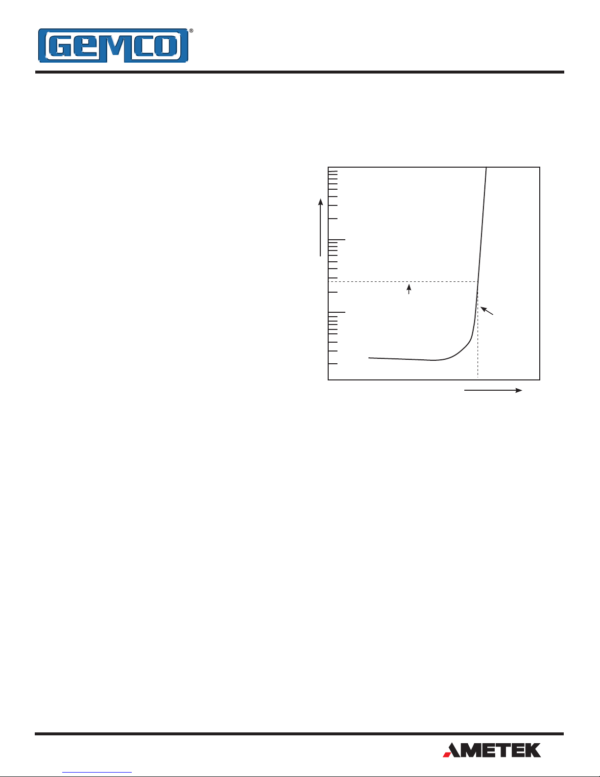
Series 115 Motogard™
The Series 115 Motogard is designed to take in up
to 6 Thermistors wired in Parallel, and has two Triac
output relays.
Connections
Power Connections:
The standard 115 Series Motogard relay is designed
to operate off of 120VAC +/-10%, Single Phase,
50/60Hz, and is sold under part number 115101-
2. There is a special 230VAC input power version
available and sold under part number 115202-2.
On terminals 1 & 2 connect incoming AC
power.
Thermistor Connections:
1. Connect one lead of each Thermistor
to terminals 6, 7, 8, 9, 10, and 11
respectively.
2. Connect other leads of each Thermistor
to Common, terminal 5.
3. Maximum number of Thermistors in
parallel: Six (6)
4. Note: If using less than 6 Thermistors.
Any unused input – Install a 150 Ohm
1/2W resistor from sensor common
(terminal 5) to any unused input.
Output Load Connections:
1. With power applied to the controller
and all input sensors in their low
impedance states. Terminal 3 and 4
become the equivalent to a closed
contact of an electromechanical
relay.
2. With power applied to the controller
and all input sensors in their low
impedance states. Terminal 3’ and
4’ become the equivalent to a open
contact of an electromechanical
relay.
3. Be sure power is never applied directly across
the contact but always in series with the load.
4. Maximum allowable load – 5 Amps at
120/240VAC.
5. The closed output of the Motogard Over
temperature Protection System has been
specifically designed to operate directly in
series with most main line contactors. If a small
interposing relay must be used, the sealed
burden shall be greater than 10VA.
6. The open output of the Series 115 relay can be
used for trip indication.

4
FACTORY AUTOMATION
®
Phone: 248-435-0700 Toll Free: 800-635-0289 Fax: 248-435-8120 www.ametekfactoryautomation.com
Series 120 Motogard
The Series 120 Motogard is designed to take in up
to 3 Thermistors wired in Parallel, and has a single
Triac output relay.
Connections
Power Connections:
The 120 Series Motogard relay is designed to operate
off of 120VAC +/-10%, Single Phase, 50/60Hz.
Connect 120VAC to input terminals 1 and 2.
Thermistor Connections:
1. Connect one lead of each Thermistor to terminals
6, 7, and 8 respectively.
2. Connect other leads of each Thermistor to
Common, terminal 5.
3. Maximum number of Thermistors in parallel:
Three (3)
4. Note: If using less than 3 Thermistors. Any
unused input – Install a 150 Ohm 1/2W resistor
from sensor common (terminal 5) to any unused
input.
Output Load Connections:
1. With power applied to the controller and all input
sensors in their low impedance states. Terminal 3
and 4 become the equivalent to a closed contact
of an electromechanical relay.
2. Be sure power is never applied directly across the
contact but always in series with the load.
3. Maximum allowable load – 3 Amps at 120/240VAC.
4. The closed output of the Motogard Over
temperature Protection System has been
specifically designed to operate directly in
series with most main line contactors. If a small
interposing relay must be used, the sealed burden
shall be greater than 10VA.

5
FACTORY AUTOMATION
®
Phone: 248-435-0700 Toll Free: 800-635-0289 Fax: 248-435-8120 www.ametekfactoryautomation.com
Series 135 Motogard
The Series 135 Motogard is designed to take in up
to 3 Thermistors wired in Parallel, and has a Form C
Mechanical Output relay.
Connections
Power Connections:
The 135 Series Motogard relay is designed to operate
off of 120VAC +/-10%, Single Phase, 50/60Hz.
Connect 120VAC to input terminals 1 and 2.
Thermistor Connections:
1. Connect one lead of each Thermistor to terminals
6, 7, and 8 respectively.
2. Connect other leads of each Thermistor to
Common terminal 9.
3. Maximum number of Thermistors in parallel:
Three (3)
4. Note: If using less than 3 Thermistors. Any
unused input – Install a 150 Ohm 1/2W resistor
from sensor common (terminal 9) to any unused
input.
Output Load Connections:
1. Terminals 3, 4 and 5 comprise a set of “Form C”
contacts with terminal 4 common, Terminal 5 is
the open side and terminal 3 is the closed side.
2. Be sure power is never applied directly across the
contact but always in series with the load.
3. Maximum allowable load – 5 Amps at 120/240VAC
or 28VDC.
4. The closed output of the Motogard Over
temperature Protection System has been
specifically designed to operate directly in series
with most main line contactors. If contact current
is greater than 5 Amps at 115VAC, an interposing
relay must be used.
5. The open output of the Series 135 relay can be
used for trip indication.

6
FACTORY AUTOMATION
®
Phone: 248-435-0700 Toll Free: 800-635-0289 Fax: 248-435-8120 www.ametekfactoryautomation.com
Series 150 Motogard
The Series 150 Motogard is designed to take in up
to 3 Thermistors wired in Series (1 input), and has a
Form C Mechanical Output relay.
Connections
Power Connections:
The 150 Series Motogard relay is designed to operate
off of 120VAC +/-10%, Single Phase, 50/60Hz.
Connect 120VAC to input terminals 1 and 2.
Thermistor Connections:
1. Connect one lead of the series Thermistor to 3.
2. Connect other lead of the series Thermistor to
terminal 4.
3. Maximum number of Thermistors in series:
Three (3)
4. Note: Resistance input across terminals 3 and
4 should be between 150 Ohm to 500 Ohm in
ambient conditions. If the resistance measures
less than 150 Ohms a 150 Ohm 1/2W resistor
should be installed in series with the Thermistors
to prevent false trips.
Output Load Connections:
1. Terminals 5, 6 and 7 comprise a set of “Form C”
contacts with terminal 6 common, Terminal 5 is
the open side and Terminal 7 is the closed side.
2. Be sure power is never applied directly across
the contact but always in series with the load.
3. Maximum allowable load – 4 Amps at
120/240VAC.
4. The closed output of the Motogard Over
temperature Protection System has been
specifically designed to operate directly in
series with most main line contactors. If contact
current is greater than 4 Amps, an interposing
relay must be used.
5. The open output of the Series 150 relay can be
used for trip indication.

7
FACTORY AUTOMATION
®
Phone: 248-435-0700 Toll Free: 800-635-0289 Fax: 248-435-8120 www.ametekfactoryautomation.com
Available in numerous designs from a simple thermistor to a spring loaded bearing probes. Consult factory for special applications.
Item Identification
Part Number T8060* T8070* T8080* T8090 T8100 T8110 T8120* T8130 T8140 T8150 T8160 T8170 T8180* T8190*
T9060** T9070** T9080** T9090** T9100** T9110** T9120** T9130** T9140** T9150** T9160** T9170** T9180** T9190**
Centigrade
ºC +/-5º
60 70 80 90 100 110 120 130 140 150 160 170 180 190
Fahrenheit
ºF +/-9º
140 158 176 194 212 230 248 266 284 302 320 338 356 374
Identifying
wire colors
White /
Gray
White /
Brown
White /
White
Green /
Green
Red / Red Brown /
Brown
Grey /
Grey
Blue /
Blue
White /
Blue
Black /
Black
Blue /
Red
White /
Green
White /
Red
Black /
Grey
*Consult factory - Non-stocked temperatures. Consult factory for mimimums
**Consult factory - Special order item. Consult factory for mimimums
Switching temperatures (Nominal)

Over – Temperature Protection System
Motogard Relay Models
*Series 115 and 120 Motogard Controllers use output
Triacs that have been specifically selected to operate
directly in series with main line contactors. If a small
interposing relay must be used, the sealed VA rating
of the interposing relay should be greater than 10VA.
Model No.
Series 115 Series 120 Series 135 Series 150
115101-2 120101 135101 150101
Operating
Characteristics
6 Inputs
2 Triac Outputs
1 N.O.* 1 N.C.*
3 Inputs
Single Triac Output
N.C.*
3 Inputs
Form C Relay Output
1 Input
Form C Relay Output
Input Rating 120VAC± 10%, Single Phase, 50/60 Cycles
Output Rating 120/240 Volts AC
5 amp continuous
120/240 Volts AC
3 amp continuous
120/240 Volts AC
or 28 Volts DC
5 amp continuous
120/240 Volts AC
4 amp continuous
Input
Resistance
Control
Controller ON with 500 ohms
or less - OFF with approx.
1500 ohms or more
Controller ON with 500 ohms
or less - OFF with approx.
1500 ohms or more
Controller ON with 150 to 500
ohms - OFF with approx. 1500
ohms or more
Controller ON with 150 to 500
ohms - OFF with approx. 3500
ohms or more
Isolation
Controller output, excitation,
and sesor input electrically
isolated from each other
Controller excitation only
isolated from output and
sensors
Controller output, excitation,
and sesor input electrically
isolated from each other
Controller output, excitation,
and sesor input electrically
isolated from each other
Reset Automatic
Dimensions 5.50" W x 4.25" L x 3.12"H 3.24" W x 2.25" L x 2.50" H 5.75" W x 2.0" L x 5.68" H 3.25" W x 2.25" L x 2.50" H
Enclosure Potted in "NEMA" 12 steel case Potted in polyester case Mounted in welded steel case Potted in polyester case
1080 North Crooks Road, Clawson, MI 48017
Phone: 248-435-0700 Toll Free: 800-635-0289
Fax: 248-435-8120 www.ametekfactoryautomation.com
MOTO.M4R
3/18 Z416
MADE IN AMERICA
Other Products
Copyright 2016 by AMETEK FACTORY AUTOMATION. All Rights Reserved. Made in the USA.
This manual suits for next models
3
Table of contents