IP 20 - START
2
1 - GENERAL
• It is the responsibility of the
owner or user to ensure that the
installation, operation and maintenance
of the STV 2313 and its options are
carried out by experienced and
qualified personnel, and comply with
legislation relating to the safety of
equipment and personnel as well as
current regulations in the country of
use.
1.1 - Function
The IP 20 - START kit is designed to
increase the protection index of
DIGISTART STV 2313 electronic starters
to IP 20.
The overall height of the DIGISTART STV
2313 is altered by adding the kit.
Association of IP 20 - START with
DIGISTART STV 2313
Note: There is no IP 20 kit for ratings
above 250. However, STV 2313 365 to
900 have IP 20 protection on 5 sides as
standard.
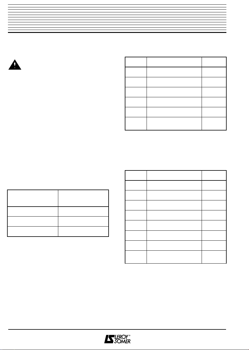
1.2 - Kit composition
1.2.1 - IP 20 - START - 1
Note: The screws (4) and the prestole
rings (5) are supplied mounted on the
metal support plate.
1.2.2 - IP 20 - START - 2
Note: 12 of the screws (6) and the
prestole rings (5) are supplied mounted on
the metal support plate.
IP 20 - START
7
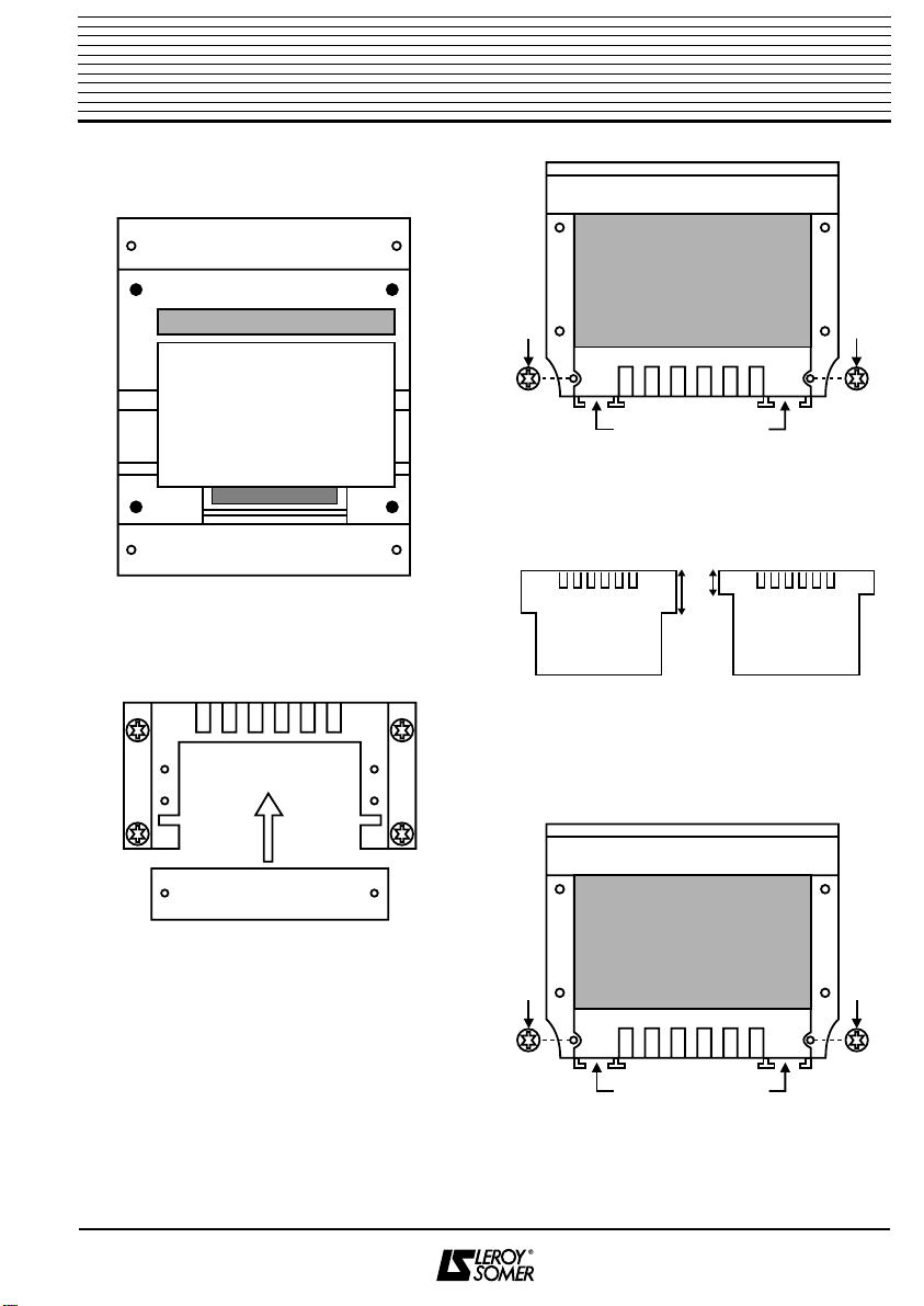
2.2.3 - IP 20 - START 3
a) Remove the terminal cover and 3 SIM
No. 8 screws from the bottom of the STV
2313.
b) Fit the support (2) and fix it in place
using the 3 SIM No. 8 screws removed
earlier.
c) Undo the screws (3) and remove the
cover (2).
d) Insert the STV 2313.
e) Wire up the STV 2313.
Note: Run the control module cables
through "PLEXO" cable glands to avoid
interference from the power cables.
f) Replace the cover (2).
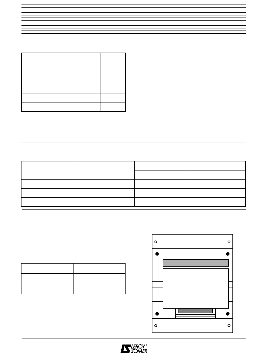
DIGISTART
STV 2313 rating
IP 20 - START
reference
37 1
60 and 86 2
145 to 250 3
Number Description Quantity
1Support 2
2Movable part 2
3Terminal cover 2
4M4 x 8 T20 + F screws 12
5Prestole ring Ø4 12
6SIM no. 4 x 6.5
T10 + F screws 4
Number Description Quantity
1Support 2
2Movable part 2
3Terminal cover 2
4Upper protective cover 1
5Lower protective cover 1
6M4 x 8 T20 + F screws 16
7Prestole ring 12
8SIM no. 4 x 6.5
T10 + F screws 4
3 SIM No. 8 screws removed
SIM No. 8 screws
25
1
25
1
3 3