GENASYS 3RU User manual

3RU AMPLIFIER
GENASYS INC.
GENASYS 3RU AMPLIFIER
USER MANUAL
16262 West Bernardo Drive
San Diego, CA 92127
www.genasys.com
Manual Part No.: 119456-00 Rev. B
Revised: Oct. 2020
CAGE: 1K3W7
Copyright, 2020, Genasys Inc.
FAULT
AMPLIFIER ON
POWER


3RU AMPLIFIER
GENASYS INC.
Manual Part NO.: 119456-00 Rev. B
i
Contents
1.0 Safety Information ................................................................................................................... 1
2.0 Overview .................................................................................................................................. 2
3.0 System Details.......................................................................................................................... 3
3.1 Front Panel........................................................................................................................... 3
3.2 Rear Panel: AC...................................................................................................................... 4
3.3 Rear Panel: DC...................................................................................................................... 4
3.4 Connectors: Plugs, Housings, Adaptors ............................................................................... 5
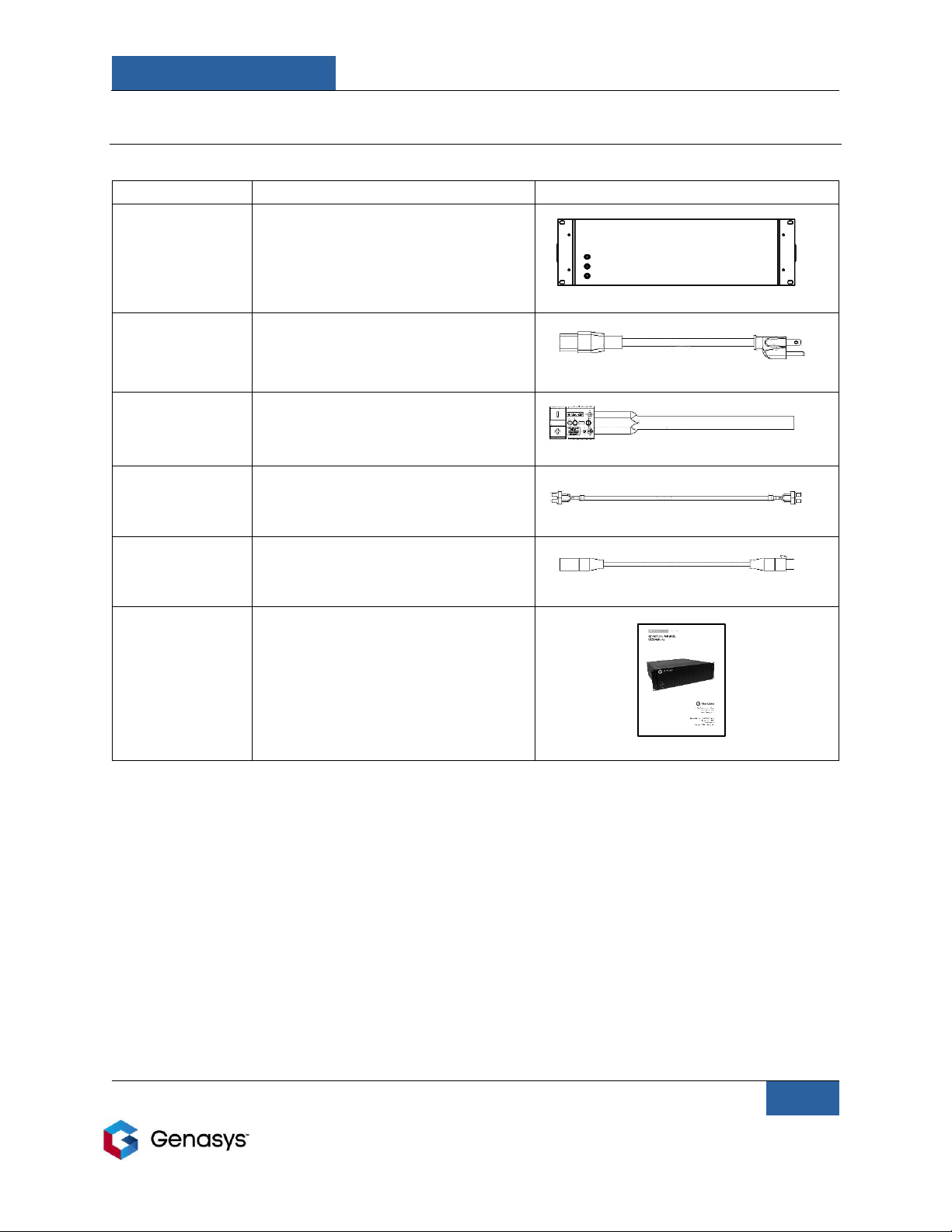
4.0 Parts List................................................................................................................................... 7
5.0 Installation ............................................................................................................................... 8
6.0 Connect 3RU to 2RU ................................................................................................................ 9
7.0 Connect 3RU to 3RU (3RU Daisy Chain)................................................................................. 10
8.0 Connecting Array of Units...................................................................................................... 12
9.0 Connecting 3RU to DS-60XL Horn Speaker(s) ........................................................................ 13
10.0 Contact Closure Remote Interface....................................................................................... 14
11.0 Frequency Response ............................................................................................................ 14
12.0 Maintenance ........................................................................................................................ 15
13.0 Troubleshooting................................................................................................................... 15
14.0 Specifications ....................................................................................................................... 16
15.0 Technical Support ................................................................................................................ 17

3RU AMPLIFIER
GENASYS INC.
Manual Part NO.: 119456-00 Rev. B
1
1.0 Safety Information
Note the following safety instructions when assembling, operating, and storing the Genasys
3RU Amplifier.
•Read and adhere to the instructions detailed in this manual. Keep this manual with the 3RU
Amplifier at all times.
•Make sure all steps are properly taken during assembly and operation. Failure to follow
these steps may result in damage to the device.
•Do not bend, twist, or pinch cables, especially at connection points.
•Make sure all cable connection ports are kept clean and clear of debris.
•Only use attachments/accessories specified by Genasys.
•Refer all servicing and maintenance to qualified personnel.

3RU AMPLIFIER
GENASYS INC.
Manual Part NO.: 119456-00 Rev. B
2
2.0 Overview
The Genasys 3RU is a compact, rugged amplifier designed to connect to one or more Genasys
speaker devices.
There are two different options for the 3RU Amplifier, an AC Version (118924-00) and a DC
Version (118925-00). The AC Version operates on 100-250 VAC of input power. The DC Version
operates on 24 VDC of input power.
The 3RU Amplifier is designed to connect with the Genasys 2RU Command and Control Unit.
The 3RU Amplifier can also be daisy chained with other 3RU Amplifiers. Daisy chaining allows a
single audio input source to drive all the amplifiers in an array and increases the number of
speakers that can broadcast the audio file.

3RU AMPLIFIER
GENASYS INC.
Manual Part NO.: 119456-00 Rev. B
3
3.0 System Details
This section illustrates the various interfaces and components found within the 3RU Amplifier
Unit.
3.1 Front Panel
POWER
LED illuminates green when power is present
AMPLIFIER ON
LED illuminates green when the amplifier is turned on
FAULT
LED illuminates red when the amplifier has reported a general fault
and has shut down or failed

3RU AMPLIFIER
GENASYS INC.
Manual Part NO.: 119456-00 Rev. B
4
3.2 Rear Panel: AC
3.3 Rear Panel: DC
SPEAKER OUTPUTS
Sends audio out to Genasys speakers
CONTROL: INPUTS
Receives control connections from other 3RU or 2RU units
CONTROL: OUTPUTS
Sends control connections to other 3RU or 2RU units
AUDIO: INPUTS
Receives audio signals from other 3RU or 2RU units
AUDIO: OUTPUTS
Sends audio signals to other 3RU or 2RU units
POWER IN
AC: Receives 100-250 VAC input
DC: Receives 24 VDC input
AC: Power switch with built-in
resettable circuit breaker
DC: Resettable fuse

3RU AMPLIFIER
GENASYS INC.
Manual Part NO.: 119456-00 Rev. B
5
3.4 Connectors: Plugs, Housings, Adaptors
110984-00: CONNECTOR, PLUG,
5.08mm, 4 POS, SCREW TERM
Speaker Output Connector
110220-00: CONNECTOR, PLUG,
5.08mm, 8 POS, SCREW TERM
Control Input and Output Connector
118662-00: HOUSING, CONNECTOR,
HEAVY DUTY, 120 AMP, GRAY
DC only: Power Input
11866-00: AC POWER CONNECTOR
RECEPTACLE, MALE, PANEL MOUNT
AC only: Power Input

3RU AMPLIFIER
GENASYS INC.
Manual Part NO.: 119456-00 Rev. B
6
117329-00: CONN, ADAPTER, RCA
TO RCA, PANEL MOUNT, FEMALE
Audio Input and Output Connector
117333-00: CONN, PLUG, XLR
PANEL MOUNT, 3POS, FEMALE
Audio Input Connector
118911-01: CONN PLUG, XLR PANEL
MOUNT, 3POS, BLACK, MALE
Audio Output Connector

3RU AMPLIFIER
GENASYS INC.
Manual Part NO.: 119456-00 Rev. B
7
4.0 Parts List
Before beginning installation, make sure the 3RU Amplifier was shipped with everything
included in the parts list and that there was no damage sustained during shipment. If there are
any issues, contact your Genasys sales representative.
Part Number
Item Description
Image
119097-00 (AC)
119098-00 (DC)
3RU Amplifier, with Rail Mounts
119143-00
(AC only)
Power Cord, IEC 320-C19, 20 AMP,
2.5 M Long
118936-01
(DC only)
Cable Assy, Power, Heavy Duty
Contact, Gray, 4 AWG,
Unterminated Ends, 10 FT
117854-05
Cable Assy, Red Ferrule, Cable
2Wire, 18 AWG, Red Ferrule, 14 IN
(QTY: 2)
118938-00
Cable, XLR Male to XLR Female, 16
AWG, Gold, 3 FT
119456-00
Manual, Printed, 3RU Amplifier

3RU AMPLIFIER
GENASYS INC.
Manual Part NO.: 119456-00 Rev. B
8
5.0 Installation
The 3RU Amplifier is designed to be installed in standard Electronic Industries Alliance (EIA)
amplifier rack-mounting systems.
Users should avoid installing the 3RU near a heat source.
Make sure the 3RU is installed in a location with good ventilation and air flow.
Make sure power cord is properly grounded before turning on the 3RU. If the provided plug
does not fit into your outlet, consult an electrician.
Follow the instructions in the following sections to connect your 3RU Amplifier with external
control sources, other 3RU units, and speakers.

3RU AMPLIFIER
GENASYS INC.
Manual Part NO.: 119456-00 Rev. B
9
6.0 Connect 3RU to 2RU
In most amplifier arrays, the 3RU Amplifier(s) will be connected to a 2RU Command and Control
Unit. The 2RU acts as the audio source, as well as the control unit, for all the rack-mounted 3RU
units. To connect the 3RU to the 2RU, take the following steps:
1. 2RU: Audio Output → 3RU: Audio Input [BLUE]
2. 2RU: Contact Closure Output 4a → 3RU: CONTROL ON Input [GREEN]
3. 2RU: Contact Closure Input 4→ 3RU: CONTROL FAULT Output [RED]
Though the following wiring diagram uses a DC Unit, AC Units
follow the same connection pattern.
2RU Command and Control Unit
3RU Amplifier Unit (DC)
LEGEND
•Audio Connection: BLUE
oPN: 118938-00
•ON/OFF Connection: GREEN
oPN: 117854-05
•Fault Connection: RED
oPN: 117854-05
ON FAULT NOT USED
ON FAULT NOT USED

3RU AMPLIFIER
GENASYS INC.
Manual Part NO.: 119456-00 Rev. B
10
7.0 Connect 3RU to 3RU (3RU Daisy Chain)
Several 3RU amplifier units can be connected to maximize the effectiveness of the amplifiers
via daisy chain. Daisy chaining 3RUs allows a single audio input source to drive all the amplifiers
in an array. This daisy chain configuration also maximizes the number of speakers that can
connect to an array.
NOTE: 3RU Unit 1 must already be connected to the 2RU Unit (see previous diagram) or
another audio source.
Take the following steps to create a 3RU daisy chain.
1. 3RU1: AUDIO Output → 3RU2: AUDIO Input [BLUE]
2. 3RU1: CONTROL ON Output → 3RU2: CONTROL ON Input [GREEN]
3. 3RU1: CONTROL FAULT Input → 3RU2: CONTROL FAULT Output [RED]
This pattern will be repeated for each additional 3RU Unit in the Daisy Chain.
The wiring diagram on the following page shows multiple 3RU amplifiers connected via daisy
chain.
When looking at the diagrams on the following pages, use this legend:
LEGEND
•Audio Connection: BLUE
oPN: 118938-00
•ON/OFF Connection: GREEN
oPN: 117854-05
•Fault Connection: RED
oPN: 117854-05

3RU AMPLIFIER
GENASYS INC.
Manual Part NO.: 119456-00 Rev. B
11
3RU Daisy Chain Diagram
Though the following wiring diagram uses AC Units, DC Units follow the same pattern.
3RU Amplifier Unit 1 (AC)
3RU Amplifier Unit 2 (AC)
3RU Amplifier Unit 3 (AC)
These connections will continue to subsequent
3RU units, following the same pattern.
ON FAULT NOT USED
ON FAULT NOT USED
ON FAULT NOT USED
ON FAULT NOT USED
ON FAULT NOT USED
ON FAULT NOT USED

3RU AMPLIFIER
GENASYS INC.
Manual Part NO.: 119456-00 Rev. B
12
8.0 Connecting Array of Units
When an array of units (made up of a 2RU Command and Control Unit and one or more 3RU
Amplifier Units) is connected, it will appear as shown in the diagram below.
Though the following wiring diagram uses DC Units, AC Units follow the same pattern.
2RU Command and Control Unit
3RU Amplifier Unit 1 (DC)
3RU Amplifier Unit 2 (DC)
ON FAULT NOT USED
ON FAULT NOT USED
ON FAULT NOT USED
ON FAULT NOT USED

3RU AMPLIFIER
GENASYS INC.
Manual Part NO.: 119456-00 Rev. B
13
9.0 Connecting 3RU to DS-60XL Horn Speaker(s)
A single 3RU Amplifier can connect with up to eight DS-60XL horn speakers. When daisy
chained, one audio signal can be broadcast simultaneously through numerous speakers across
multiple amplifiers.
The DS-60XL horn speaker has a two-conductor speaker cable. To connect the speaker to the
3RU, connect this cable to one of the speaker output channel plugs on the back of the 3RU.
Each of the two pins on the cable must be inserted into the corresponding (+) and (-) plugs in
the desired speaker output channel. Each speaker output channel is designed to connect to a
single speaker.
This diagram illustrates how the 3RU can connect with up to eight DS-60XL speakers:
Though the following wiring diagram uses an AC Unit, DC Units follow the same pattern.
ON FAULT NOT USED
ON FAULT NOT USED
DS-60XL
Speaker 1
DS-60XL
Speaker 3
DS-60XL
Speaker 2
DS-60XL
Speaker 4
DS-60XL
Speaker 5
DS-60XL
Speaker 7
DS-60XL
Speaker 6
DS-60XL
Speaker 8

3RU AMPLIFIER
GENASYS INC.
Manual Part NO.: 119456-00 Rev. B
14
10.0 Contact Closure Remote Interface
The 3RU amplifier utilizes Phoenix Contact Connectors for remote monitoring and control of
the following functions via contact closures:
Remote Power ON/OFF
Closed = ON
Open = OFF
Non-latching Fault
Closed = Amplifier Faulted
11.0 Frequency Response
Frequency response is optimized for use with Genasys technology.
The following chart depicts frequency at various root mean square (RMS) levels:

3RU AMPLIFIER
GENASYS INC.
Manual Part NO.: 119456-00 Rev. B
15
12.0 Maintenance
•Avoid placing 3RU in locations subject to excessive heat, humidity, or moisture.
•Allow enough free space around the unit for normal ventilation.
•Avoid exposure to excessive smoke and dust.
•Clean surfaces and connectors with a dry, soft cloth. Never use thinners, benzene, alcohol,
or any other chemicals.
13.0 Troubleshooting
If you experience any of the issues listed below while operating your 3RU Amplifier, follow the
provided troubleshooting procedures. If these procedures do not remedy your issue, contact
your Genasys sales representative.
Issue
Cause
Solution
POWER light is not
illuminated.
The amplifier unit is not
receiving power.
Ensure that the power source
is properly connected to the
POWER IN input.
AMPLIFIER ON light is not
illuminated.
CONTROL inputs and outputs
are not properly configured.
Ensure that FAULT and
ON/OFF connections are
properly connected.
No audio coming from the
unit.
Unit may not be properly
connected to speakers
and/or other amplifier units.
Ensure that speakers are
properly connected, and that
all other connections follow
the patterns laid out in this
manual.
FAULT light is illuminated.
The unit sensed an internal
issue and shut down.
Disconnect the unit and let
sit. Reconnect. If this does
not work, contact your
Genasys sales representative.

3RU AMPLIFIER
GENASYS INC.
Manual Part NO.: 119456-00 Rev. B
16
14.0 Specifications
Mechanical
Weight
AC: 22.7 lbs. (10.3 kg)
DC: 17.0 lbs. (7.7 kg)
Dimensions
H=5.25” W=19” D=18” (13.3 cm x 48.3 cm x 45.7 cm)
Construction
Aluminum Chassis; RoHS compliant
Airflow Requirement
32 CFM
Electrical
Power Input
AC: 100-250 VAC (50/60 Hz)
DC: 24 VDC (70 A max)
Frequency Response
300 Hz – 10 kHz
THD+N
<2% @ 1 kHz @ rated power
Power-On Time
Less than one second from power-on to playing at full output
Max Power Consumption
AC: 2000 W
DC: 1550 W
Average Power Consumption
AC: 280 W
DC: 210 W
Standby Power Consumption
AC: 85 W
DC: 55 W
Inrush Current
AC: 26 A (peak)
DC: 174 A (peak)
Electromagnetic Compliance
FCC Class A radiated and conducted, CISPR 22:2008, CE
Acoustic
Audio Input
RCA (1 VRMS, unbalanced)
XLR (2 VRMS, balanced)
Audio Output
RCA (1 VRMS, unbalanced)
XLR (2 VRMS, balanced)
Speaker Outputs
Four Phoenix Contact Connectors

3RU AMPLIFIER
GENASYS INC.
Manual Part NO.: 119456-00 Rev. B
17
15.0 Technical Support
Contact information for Genasys Technical Support is listed below.
Genasys Inc.
16262 West Bernardo Drive
San Diego, CA 92127
858-676-0574
Technical@genasys.com
Table of contents