manuals.online logo
Brands
  1. Home
  2. •
  3. Brands
  4. •
  5. Genelec
  6. •
  7. Rack & Stand
  8. •
  9. Genelec 8000-202B User manual

Genelec 8000-202B User manual

5. MONITOR ADJUSTING
Variable adjustments for
tilting angle, direction and rotation.
5.a Hold the monitor
5.b Loosen both grub screws 2.5 by
5.b half a turn so that they are still in
5.b mesh with the retaining bolt 1.3
5.b WARNING!
5.b In the case of non-observance
5.b so that the grub screws 2.5 and
5.b the retaining bolt 1.3 are not
5.b engaged, the joint body 2.4
5.b together with the monitor could
5.b fall to ground.
5.c Place the monitor in the desired
5.c position. See Settings in section 6.
5.d Re-tighten both grub screws 2.5.
5.d as shown in section 4.c.
5.d Tightening torque: ~6Nm.
6. SETTINGS
6.a TILTING ANGLE:
6.a - swivel range
6.a - up +90°
6.a - down -90°
6.b TWISTING:
6.b - horizontal rotation 360°
6.c DIRECTION:
6.c - vertical rotation 360°
7. DIMENSIONS
7.a Distance
7.b Cable bushing
7.c Ceiling plate
7.d Monitor plate
CORRECT: loosened, but
still in mesh
WARNING: not engaged!
swivel range up/down +/-90°
Distance Cable bushing Ceiling plate Monitor plate
horizontal
rotation
360°
vertical
rotation
360°
bottom-up
view
TECHNICAL DATA
CHECKING, MAINTENANCE, CLEANING
- During maintenance work, watch out for possible injuries.
- Inspect bolted assemblies regularly.
- For cleaning, it is the best to use a damp cloth with a mild, nonabrasive detergent.
HAZARDS – Measures
HAZARD: Monitor becomes loose from the fixing plate
Measures:
- Assemble monitor carefully (see section 4)
- Fix the monitor with a steel wire rope (see reg. BGI 810-3, 3.5)
HAZARD: Unintentional loosening of the screw joints
Measures:
- Tighten the screws as specified; (see specified torque)
- Inspect the tightness of bolted assemblies regularly
HAZARD: Maintenance and Settings
Measures:
- Activities must carried out by trained personnel
- When operating with the speaker keep clear the area below
Material
tubes, plates - steel, black powder coated
joint body - zinc die-cast, black powder coated
grub screws, ball joint - steel, zinc plated
Load GENELEC monitors, max. 5 kg
Dimensions
monitor plate: 90 x 40 mm, hole pattern: 70-76.2 mm
ceiling plate: 95 x 95 mm, hole pattern: 62 x 62 mm
distance: 158,5 mm, tube: ø 32 mm
Weight net: 0.7 kg
Card Box 160 x 110 x 100 mm, gross weight: 0.8 kg
SICHERHEITSHINWEISE
- Nur für GENELEC Monitore: 6010/8010/4010/G One/8x20/4020/G Two
- Nicht für Außen- bzw. Feuchträume
- Beachten Sie die örtlich gültigen Befestigungsanweisungen
-(evtl. abweichend von den Beispielen in Kapitel 2.)
- Benutzen Sie 4 Schrauben/Anker für die Wandbefestigung
- Montage durch ausgebildetes Installationspersonal
- Montage nur an geeigneter Wand/Decke mit entsprechendem
-Montagematerial (nicht im Lieferumfang)
- Ungeeignet sind Wände/Decken die zu schwach sind oder hinter
-denen Strom- und Wasserleitungen oder dgl. verlegt sind.
-Im Zweifel einen qualifizierten Fachmann zu Rate ziehen.
- Prüfen Sie regelmäßig die Festigkeit der Installation.
- Das Kugelgelenk ist durch zwei Gewindestifte (2.5) mit dem Halterohr
-verbunden; diese müssen stets fest angezogen sein (6Nm) und dürfen
-nur bei Neuausrichtung der Box gelockert werden. Dabei die Box durch
eine zweite Person halten lassen, um ein Wegkippen zu verhindern.
- Aufmerksame Handhabung erforderlich, da die
Verstellmöglichkeiten Einklemmgefahren bergen
GEBRAUCHSANLEITUNG
1. BESTANDTEILE
1. Deckenhalter: 1.1 Deckenplatte - 1.2 Haltearm - 1.3 Klemmbolzen
2. Monitorhalter: 2.1 Monitorplatte - 2.2 Flanschschraube M6 x 16 mm -SW4 - 2.3 Kugelgelenkbolzen
2.4 Gelenkkörper - 2.5 Gewindestift mit Spitze M6 x 10 mm, SW3 (2x)
3. Zubehörbeutel: 3.1 Schlüssel SW3 - 3.2 Schlüssel SW4 - 3.3 Flanschschraube M6 x 12 mm -SW4 (2x)
2. DECKENMONTAGE/OPTIONEN
Beachten Sie die Beschaffenheit der Decke:
- Beton, Vollstein - siehe 2.b.1
- Holz - siehe 2.b.2
- Lochsteine, - Trockenbauelemente, - u.a.
erfordern spezielle Dübel/Verankerungen.
Im Zweifel einen Experten zu Rate ziehen.
2.a Deckenplatte ausrichten und Bohrlöcher markieren
2.b Bohren der vier Löcher / OPTIONEN
2.b.1 Universaldübel: ø6 - Loch ø6 - Schraube ø4-5
2.b.1 Universaldübel: ø8 ø8 ø6
2.b.2 Holzschrauben: --- ø3 ø5
2.b.2 (ohne Dübel) --- ø4 ø6
2.c Bohrlöcher ausblasen und ggf. Dübel setzen.
2.d Deckenplatte mit vier Schrauben/Dübeln befestigen. (siehe 2.b).
3. KABEL-INSTALLATION
BEACHTE:
bei Unterputz-
Kabel-Installation
- Öffnung Deckenplatte:
-ø 29 mm
- Kabelausgang:
-35 x 16 mm
8000-202B/W Deckenhalterung für GENELEC 6010/8010/4010/G One/8x20/4020/G Two
4. MONTAGE des MONITORS
4.a
Halteplatte an den
GENELEC-Monitor schrauben.
Beide Schrauben M6 x 12 mm 3.3
per Schlüssel SW4 3.2
mit 8Nm anziehen.
4.b
Monitor sicher halten und den
Gelenkkörper 2.4 über den Klemm-
bolzen 1.3 des Deckenhalters schieben.
4.c.
SICHERUNG des Monitors:
Beide Gewindestifte 2.5 mittels
Schlüssel SW3 3.1 eindrehen und
zunächst nur leicht anziehen.
Nun ist der Monitor gegen Herunterfallen geschützt.
Zur endgültigen POSITIONIERUNG des Monitors siehe Kap.5.
4.d
Die DEMONTAGE erfolgt in umgekehrter Reihenfolge. Dabei den Monitor stets sicher halten. GENELEC Oy
Olvitie 5, Fin-74100 Iisalmi, www.genelec.com
24476-000-55/57 Rev.09 03-80-901-00 2/18
5. MONITOR EINSTELLEN
Stufenlos verstellbar in
Richtung, Neigung und Rotation
5.a Monitor festhalten.
5.b Beide Gewindestifte 2.5 wieder
5.b eine halbe Umdrehung lösen.
5.b WARNUNG!
5.b Werden die Gewindestifte 2.5 zu
5.b weit gelöst, so dass sie nicht mehr
5.b in den Klemmbolzen 1.3 eingreifen,
5.b kann der Gelenkkörper 2.4 mitsamt
5.b Monitor zu Boden fallen.
5.c Monitor in gewünschte Position bringen.
5.c Siehe Einstellmöglichkeiten in Kapitel 6.
5.d Beide Gewindestifte 2.5 wieder
5.d festdrehen wie dargestellt
5.d in Kapitel 4.c.
5.d Anzugs-Drehmoment: ~6Nm.
6. EINSTELLUNGEN
6.a NEIGUNGSWINKEL:
6.a - Schwenkbereich
6.a - auf +90°
6.a - ab -90°
6.b VERDREHUNG:
6.b - Horizontale Rotation 360°
6.c RICHTUNG:
6.c - Vertikale Rotation 360°
7. ABMESSUNGEN
7.a Abstände
7.b Kabeldurchführung
7.c Deckenplatte
7.d Monitorplatte
KORREKT: Gewindestifte gelöst,
aber stets im Eingriff
WARNUNG: Nicht im Eingriff!
Schwenkbereich auf/ab +/-90°
Abstände Kabeldurchführung Deckenplatte Monitorplatte
Horizontale
Rotation
360°
Vertikale
Rotation
360°
Ansicht
von unten
TECHNISCHE DATEN
WARTUNG, PRÜFUNG, REINIGUNG
- Bei Wartungsarbeiten auf Gefährdungen (Einklemmen, Anstoßen etc.) achten und entsprechend sichern.
- Regelmäßig Festigkeit der Schraubverbindungen überprüfen.
- Reinigen mit einem leicht feuchten Tuch und nicht scheuerndem Reinigungsmittel.
RISIKEN – Maßnahmen
RISIKO: Monitor löst sich von der Halteplatte
Maßnahmen:
- Monitor sorgfältig montieren (siehe Kapitel 4)
- Sicherungsseil anbringen (siehe BG-Vorschrift BGI 810-3, 3.5)
RISIKO: Verschraubungen lösen sich ungewollt
Maßnahmen:
- Festdrehen der Schrauben mit den angegebenen Drehmomenten
- Regelmäßig die Festigkeit der Verschraubungen überprüfen
RISIKO: Wartung und Verstellung
Maßnahmen:
- Ausführung nur durch fachkundiges Personal
- Kein Aufenthalt von Personen während der Arbeiten erlaubt
Material
Rohr, Platten - Stahl, schwarz pulverbeschichtet
Gelenkkörper - Zink-Druckguß, schwarz pulverbeschichtet
Gewindestifte, Kugelgelenk - Stahl, verzinkt
Last GENELEC Monitore, max. 5 kg
Abmessungen
Monitorplatte: 90 x 40 mm, Lochabstand: 70-76,2 mm
Deckenplatte: 95 x 95 mm, Bohrabstand: 62 x 62 mm
Wandabstand: 158,5 mm, Rohr: ø 32 mm
Gewicht netto: 0,7 kg
Karton 160 x 110 x 100 mm, brutto: 0,8 kg
SAFETY INSTRUCTIONS
- Only for GENELEC monitors:
-6010/8010/4010/G One/8x20/4020/G Two
- Not suitable for outdoors or moist rooms
- Please refer to local mounting instructions
-(may possibly deviate from the examples provided in section 2.)
-Use 4 screws/anchors for the ceiling mount
-Only use trained technicians to install the system
- Only mount on suitable ceilings with the corresponding
-mounting materials (not included in the delivery)
- Ceilings, that are too weak or have electrical or water conduits are
-not suitable. In case of doubt consult a qualified technician.
- Check the stability of the installation regularly.
- The universal ball joint is connected to the holding tube with two
-grub screws (2.5) and may only be loosened when changing the position
-of the loudspeaker. In this process is it best to have two people hold
-the loudspeaker to ensure that it does not dislodge.
- Careful and attentive handling is required when adjusting the monitors,
-due to the possibility of pinching or wedging of your hand.
INSTRUCTIONS
1. COMPONENTS
1. Ceiling holder: 1.1 ceiling plate - 1.2 supporting arm - 1.3 retaining bolt
2. Monitor holder: 2.1 monitor plate - 2.2 pan head screw M6 x 16 mm -SW4 - 2.3 ball joint
2.4 joint body - 2.5 pointed grub screw M6 x 10 mm -SW3 (2x)
3. Accessories: 3.1 allen wrench SW3 - 3.2 allen wrench SW4 - 3.3 pan head screws M6 x 12 mm -SW4 (2x)
2. CEILING MOUNTING & OPTIONS
Please determine ceiling fastening.
Different ceilings like:
- concrete, full brick - siehe 2.b.1
- wood - siehe 2.b.2
- perforated bricks, - drywall, - a.o. needs
different anchors. In case ask an expert.
2.a Adjust ceiling plate and mark drilling holes
2.b Drilling of the four holes / OPTIONS
2.b.1 Universal anchors: ø6 - hole ø6 - screw ø4-5
2.b.1 Universal anchors: ø8 ø8 ø6
2.b.2 Drywall screws: --- ø3 ø5
2.b.2 (w/o anchors) --- ø4 ø6
2.c Blow out holes and place anchors if needed.
2.d Bolt down the ceiling plate onto the ceiling. Use four screws (and compatible anchors).
3. CABLE SETUP
NOTE:
for in-ceiling-
cable-installation
- ceiling plate opening:
-ø 29 mm
- cable exit:
-35 x 16 mm
8000-202B/W SHORT CEILING MOUNT for GENELEC 6010/8010/4010/G One/8x20/4020/G Two
4. MONITOR MOUNTING
4.a
Bolt speaker plate to
GENELEC monitor.
Use pan-head-screws M6 x 12 mm 3.3
and the allen wrench 3.2.
Tightening torque: ~8Nm.
4.b
Hold the monitor securely and
push joint body 2.4 over the
retaining bolt 1.3 of the ceiling holder.
4.c.
SECURING the monitor:
First tighten both grub screws 2.5
slightly. Use allen wrench 3.1.
Now the monitor is protected against accidental drops.
The final POSITIONING of the monitor see section 5.
4.d
For disassembly follow the instructions in the reverse order. And always hold the monitor securely. GENELEC Oy
Olvitie 5, Fin-74100 Iisalmi, www.genelec.com
24476-000-55/57 Rev.09 03-80-901-00 2/18

This manual suits for next models

1

Other Genelec Rack & Stand manuals

Genelec RAM2-405 RM2 User manual

Genelec

Genelec RAM2-405 RM2 User manual

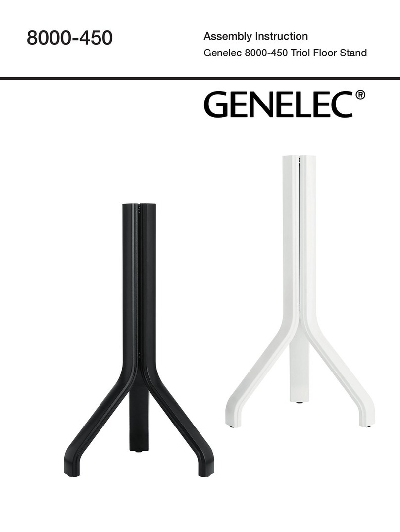
Genelec 8000-450 User manual

Genelec

Genelec 8000-450 User manual

Genelec 8000-325B User manual

Genelec

Genelec 8000-325B User manual

Genelec 8010-320 User manual

Genelec

Genelec 8010-320 User manual

Genelec 8040A User manual

Genelec

Genelec 8040A User manual

Genelec S360-424B User manual

Genelec

Genelec S360-424B User manual

Genelec 1038-437B User manual

Genelec

Genelec 1038-437B User manual

Genelec 8000-323 B User manual

Genelec

Genelec 8000-323 B User manual

Genelec 8000-420B User manual

Genelec

Genelec 8000-420B User manual

Genelec 8000-402B User manual

Genelec

Genelec 8000-402B User manual

Genelec 8260-414B User manual

Genelec

Genelec 8260-414B User manual

Genelec 8260-450B User manual

Genelec

Genelec 8260-450B User manual

Genelec S360-444B User manual

Genelec

Genelec S360-444B User manual

Genelec 8000-422B User manual

Genelec

Genelec 8000-422B User manual

Genelec 8260-465B User manual

Genelec

Genelec 8260-465B User manual

Genelec 1032-460B User manual

Genelec

Genelec 1032-460B User manual

Genelec 8000-333B User manual

Genelec

Genelec 8000-333B User manual

Genelec 04 User manual

Genelec

Genelec 04 User manual

Genelec 8000-450 User manual

Genelec

Genelec 8000-450 User manual

Genelec F One User manual

Genelec

Genelec F One User manual

Popular Rack & Stand manuals by other brands

Vivo STAND-SIT2S instruction manual

Vivo

Vivo STAND-SIT2S instruction manual

Westfalia 94 40 41 instruction manual

Westfalia

Westfalia 94 40 41 instruction manual

Iiyama MD 052W7115 manual

Iiyama

Iiyama MD 052W7115 manual

Siemens 8MF1 2AS30 Series operating instructions

Siemens

Siemens 8MF1 2AS30 Series operating instructions

Sanus MF110 Assembly instructions

Sanus

Sanus MF110 Assembly instructions

Christie ML20 instruction sheet

Christie

Christie ML20 instruction sheet

Westell VirtualEdge VESR-00 manual

Westell

Westell VirtualEdge VESR-00 manual

Wallbox EIFFEL installation guide

Wallbox

Wallbox EIFFEL installation guide

MN Mounting Solutions SR-1000 Series Assembly guide

MN Mounting Solutions

MN Mounting Solutions SR-1000 Series Assembly guide

Adam Hall Gravity LTS 01 C B manual

Adam Hall

Adam Hall Gravity LTS 01 C B manual

CHIEF K0P100 installation instructions

CHIEF

CHIEF K0P100 installation instructions

HELGI HMIFSTNDRD-F user manual

HELGI

HELGI HMIFSTNDRD-F user manual

Mount-It! MI-4352LT Installation instruction

Mount-It!

Mount-It! MI-4352LT Installation instruction

WilTec 62831 Operation manual

WilTec

WilTec 62831 Operation manual

Colebrook Bosson Saunders AV/VC Intro AVS/031/001 installation instructions

Colebrook Bosson Saunders

Colebrook Bosson Saunders AV/VC Intro AVS/031/001 installation instructions

RIGTEC AIR FRAME X-15 user guide

RIGTEC

RIGTEC AIR FRAME X-15 user guide

Symphony SYK-1049 Setup instructions

Symphony

Symphony SYK-1049 Setup instructions

Panasonic ET-PKL100S installation instructions

Panasonic

Panasonic ET-PKL100S installation instructions

manuals.online logo
manuals.online logoBrands
  • About & Mission
  • Contact us
  • Privacy Policy
  • Terms and Conditions

Copyright 2025 Manuals.Online. All Rights Reserved.