Genelec 1032B User manual
Genelec 1032B
Monitoring Speaker
Operating Manual
1032B

The bi-amplified GENELEC 1032B is a two
way active monitoring speaker designed for
high output, low coloration and broad band-
width. It is based on the famous 1031A near
field monitor but offers extended low fre-
quency output with an increased maximum
SPL.
Due to its compact size, integrated con-
struction, excellent dispersion and precise
stereo imaging this speaker system is ideal
for Near Field monitoring, mobile vans,
broadcast and TV control rooms and home
studios. Designed as an active speaker,
this unit contains drivers, power amplifiers,
active crossover filtering and protection cir-
cuitry. The DCW™ Technology used provides
excellent frequency balance even in difficult
acoustic environments.
Drivers
The low frequencies are reproduced by a 10"
(250 mm) bass driver loaded in a 24 liters
vented cabinet. The -3dB point lies at 40 Hz
and the low frequency response extends
down to 36 Hz (-6dB).
The high frequency driver is a 1" (25 mm)
metal dome with pure piston behavior up to
23 kHz. The uniform dispersion control is
achieved with the revolutionary DCW Tech-
nology pioneered by Genelec.The DCW also
provides perfect phase and delay uniformity
at the crossover frequency.
Both drivers are magnetically shielded.
Crossover
The active crossover network consists of two
parallel bandpass filters. Acoustically the fil-
ters are complementary and the slopes are
24 dB/octave. The crossover frequency is set
to 1,8 kHz. Using the active crossover con-
trols ('treble tilt', 'bass tilt' and 'bass roll-off')
this speaker to be exactly matched to any
room environment.
Amplifiers
The amplifier unit is mounted to the rear of
the speaker enclosure on quick release vibra-
tion isolators, to ensure rattle free operation
and long term reliability. The bass and treble
amplifier produce respectively 180 W and 120
W of short term power. The fast, low distor-
tion amplifiers are capable of driving a stereo
system to peak output levels in excess of 124
dB SPL at 1 m. The unit incorporates a special
protection circuitry for driver overload protec-
tion and amplifier thermal overload protection.
Variable input sensitivity allows for accurate
level matching to the console output section.
Installation
Each 1032B monitor is supplied with a mains
cable and an operating manual. After unpack-
ing, place the speaker so that its acoustical
axis (see figure 2) is aimed towards the lis-
tening position. Do not place the speaker in a
horizontal position as this may cause acousti-
cal cancellation problems around the crosso-
ver frequency.
Sufficient cooling for the amplifier must
be ensured if the speaker is installed in a
restricted space such as a cabinet or inte-
grated into a wall structure. The minimum
clearance for the amplifier is 10 centimeters
(4") to any object. The space adjacent to the
amplifier must either be ventilated or suf-
ficiently large to dissipate heat so that the
ambient temperature does not rise above 35
degrees Celsius (95°F).
Before connecting up, ensure that the
mains switch is off (see figure 1). Check that
the mains voltage selector is correctly set
(Models sold in Europe have a fixed 230 V
setting). Audio input is via a 10 kOhm bal-Audio input is via a 10 kOhm bal-
anced XLR connector, but unbalanced leads
may be used as long as pin 3 is grounded
to pin 1 of the XLR (see figure 3). Once the
connection has been made, the speakers are
ready to be switched on.
Autostart function
The signal sensing Autostart function of the
loudspeaker powers it up when playback
begins. Automatic powering down of the
loudspeaker happens one hour after the
playback has ended and the loudspeaker
goes to standby mode. The power consump-
tion in standby mode is less than 0.5 watts.
The loudspeaker will automatically and rap-
idly start once an input signal is detected
from the source.
Setting the input sensitivity
The input sensitivity of each speaker can be
adjusted to match the mixing console output
level or other source by using the input sensi-
tivity control on the rear panel (see figure 1).
A small screwdriver is needed for the adjust-
ment. The manufacturer default setting for
this control is -6 dBu (fully clockwise) which
gives SPL of 100 dB @1m at -6 dBu input
level. Note that to get the full output level
of 113 dB SPL, an input level of +7 dBu is
needed at this setting.
Setting tone controls
The response of the system may have to be
adjusted to match the acoustic environment.
The adjustment is done by setting the three
tone control switch groups ‘treble tilt’, ‘bass
tilt’ and ‘bass roll-off’ on the rear panel. The
factory settings for these controls are ‘All Off’
to give a flat anechoic response. See Table 1
for suggested tone control settings. Figure 5
shows the effect of the controls on the ane-
choic response. Always start adjustment by
setting all switches to ‘OFF’ position. Then set
only one switch to the ‘ON’ position to select
the response curve needed. If more than one
switch is set to ‘ON’ (within one switch group)
the attenuation value is not accurate.
Console top mounting
If the 1032B’s are used for for near field moni-
toring, avoid mounting the speakers on the
meter bridge of the console. Instead position
them slightly behind the console by using
floor stands or wall mounts. This prevents the
the first reflections from the console surface
from coloring the direct sound.
Maintenance
No user serviceable parts are to be found
within the amplifier unit. Any maintenance
or repair of the 1032B unit should only be
undertaken by qualified service personnel.
Safety considerations
Although the 1032B has been designed in
accordance with international safety stand-
ards, to ensure safe operation and to main-
tain the instrument under safe operating con-
Genelec 1032B Monitoring Speaker
System
ditions, the following warnings and cautions
must be observed:
1. Servicing and adjustment must only
be performed by qualified service
personnel. The amplifier’s rear panel must
not be opened.
2. Do not use this product with an
unearthed mains cable or an unearthed
mains connectionas this may lead to
personal injury.
3. To prevent fire or electric shock, do not
expose the unit to water or moisture. Do
not place any objects filled with liquid,
such as vases on the speaker or near it.
4. Note that the amplifier is not
completely disconnected from the AC
mains service unless the mains power cord
is removed from the amplifier or the mains
outlet.
WARNING!
This equipment is capable of producing sound
pressure levels in excess of 85 dB, which may
cause permanent hearing damage.
Guarantee
This product is supplied with two year guaran-
tee against manufacturing faults or defects that
might alter the performance of the unit. Refer
to supplier for full sales and guarantee terms..
Compliance to FCC rules
This device complies with part 15 of the FCC
Rules. Operation is subject to the following
two conditions:
This device may not cause harmful interfer-
ence, and this device must accept any inter-
ference received, including interference that
may cause undesired operation.
N
ote: This equipment has been tested and
found to comply with the limits for a Class
B digital device, pursuant to part 15 of the
FCC Rules. These limits are designed to
provide reasonable protection against harm-
ful interference in a residential installation.
This equipment generates, uses and can
radiate radio frequency energy and, if not
installed and used in accordance with the
instructions, may cause harmful interference
to radio communications. However, there is
no guarantee that interference will not occur
in a particular installation. If this equipment
does cause harmful interference to radio or
television reception, which can be deter-
mined by turning the equipment off and on,
the user is encouraged to try to correct the
interference by one or more of the following
measures:
• Reorient or relocate the receiving
antenna.
• Increase the separation between the
equipment and receiver.
• Connect the equipment into an outlet on
a circuit different from that to which the
receiver is connected.
• Consult the dealer or an experienced
radio/TV technician for help.
Modifications not expressly approved by
the manufacturer could void the user’s au-
thority to operate the equipment under FCC
rules.
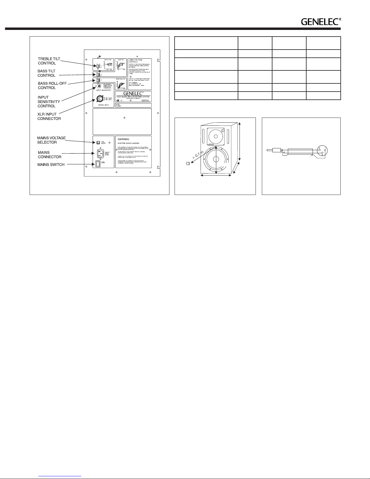
Figure 1. Amplifier panel layout of the 1032B Figure 2. Location of the acoustic axis
Speaker Mounting
Position
Treble tilt Bass tilt Bass roll-off
Flat anechoic response None None None
Free standing in a damped
room
None -2 dB None
Free standing in a
reverberant room
None -4 dB -2 dB
Near field or console bridge None -4 dB -4 dB
In a corner None -4 dB -4 dB
Table 1. Suggested tone control settings in some typical situations
Figure 3. RCA to XLR cable
Cable
Screen
RCA
(Source)
XLR
(Speaker)
290 mm
495 mm
320 mm
290 mm
1032B Operating Manual
Genelec Document D1032R001 Copyright Genelec Oy 2.2013. All data subject to change without prior notice www.genelec.com
AMPLIFIER SECTIONCROSSOVER SECTION
SYSTEM SPECIFICATIONS
Lower cut-off frequency, -3 dB: <40 Hz
Upper cut-off frequency, -3 dB: >22 kHz
Free field frequency response of system:
42 Hz - 21 kHz (±2.5 dB)
Maximum short term sine wave acoustic output on
axis in half space, averaged from 100 Hz to 3 kHz:
@ 1m > 113 dB SPL
@ 0.5m > 119 dB SPL
Maximum long term RMS acoustic output in same
conditions with IEC weighted noise (limited by
driver unit protection circuit):
@ 1m >103 dB SPL
@ 0.5m >109 dB SPL
Maximum peak acoustic output per pair above
console bridge, @ 1 m from the listening position
with music material: > 124 dB
Self generated noise level in free field @ 1m
on axis: < 10 dB (A-weighted)
Harmonic distortion at 90 dB SPL @ 1m on axis:
Freq: 50...100 Hz < 1%
> 100 Hz < 0.5%
Drivers: Bass 10" (250 mm) cone
Treble 1" (25 mm) metal dome
Both drivers are magnetically shielded.
Weight: 21,7 kg (48 Ib.)
Dimensions:
Height 495 mm (19 1/2")
Width 320 mm (12 5/8")
Depth 290 mm (11 7/16")
Bass amplifier short term output power with a
4 Ohm load:
180 W
Treble amplifier short term output power with an
8 Ohm load:
120 W
Long term output power is limited by driver unit
protection circuitry.
Slew rate 80V/µs
Amplifier system distortion at
nominal output:
THD <0.05%
SMPTE-IM <0.05%
CCIF-IM <0.05%
DIM 100 <0.05%
Signal to Noise ratio, referred to full output:
Bass > 100 dB
Treble > 100 dB
Mains voltage: 230, 100/200 or 115/230V
according to region
Voltage operating range: ±10%
Power consumption:
Idle 20 W
Standby <0.5 W
Full output 200 W
Input connector XLR female:
pin 1 gnd
pin 2 +
pin 3 -
Input impedance: 10 kOhm balanced
Input level for 100 dB SPL output @ 1m:
variable from +6 to -6 dBu
Input level for maximum short term sine wave output
113 dB SPL @1m:
variable from +19 to +7 dBu
Subsonic filter below 40 Hz : 18 dB/octave
Ultrasonic filter above 25 kHz: 12 dB/octave
Crossover frequency, Bass/Treble: 1.8 kHz
Crossover acoustical slopes:
24 - 32 dB/octave
Treble tilt control operating range in 2 dB steps:
from +2 to -4 dB & MUTE
Bass roll-off control operating range in 2 dB steps:
from 0 to -8 dB @ 40 Hz
Bass tilt control operating range in 2 dB steps:
from 0 to -8 dB @ 80 Hz
& MUTE
The 'CAL' position is with all tone controls set to 'off'
and the input sensitivity control to maximum (fully
clockwise).
International enquiries:
Genelec, Olvitie 5
FIN-74100, Iisalmi, Finland
Phone +358 17 83881
Fax +358 17 812 267
Email [email protected]
In the U.S. please contact:
Genelec, Inc., 7 Tech Circle
Natick, MA 01760, USA
Phone +1 508 652 0900
Fax +1 508 652 0909
Email [email protected]
AUDIO PRECISION 1032anec vs 02 FEB 93 18:51:59
60
65
70
75
80
85
90
80
85
90
95
LEVEL(dBr)
20 100 1k 10k 20k
FREQ(Hz)
BASS TILT
TREBLE TILT
BASS ROLL-OFF
AUDIO PRECISION 1032anec vs 02 FEB 93 18:56:42
80
85
90
95
100
LEVEL(dBr)
20 100 1k 10k 20k
FREQ(Hz)
0°
15°
30°
45°
65
70
75
80
85
90
95
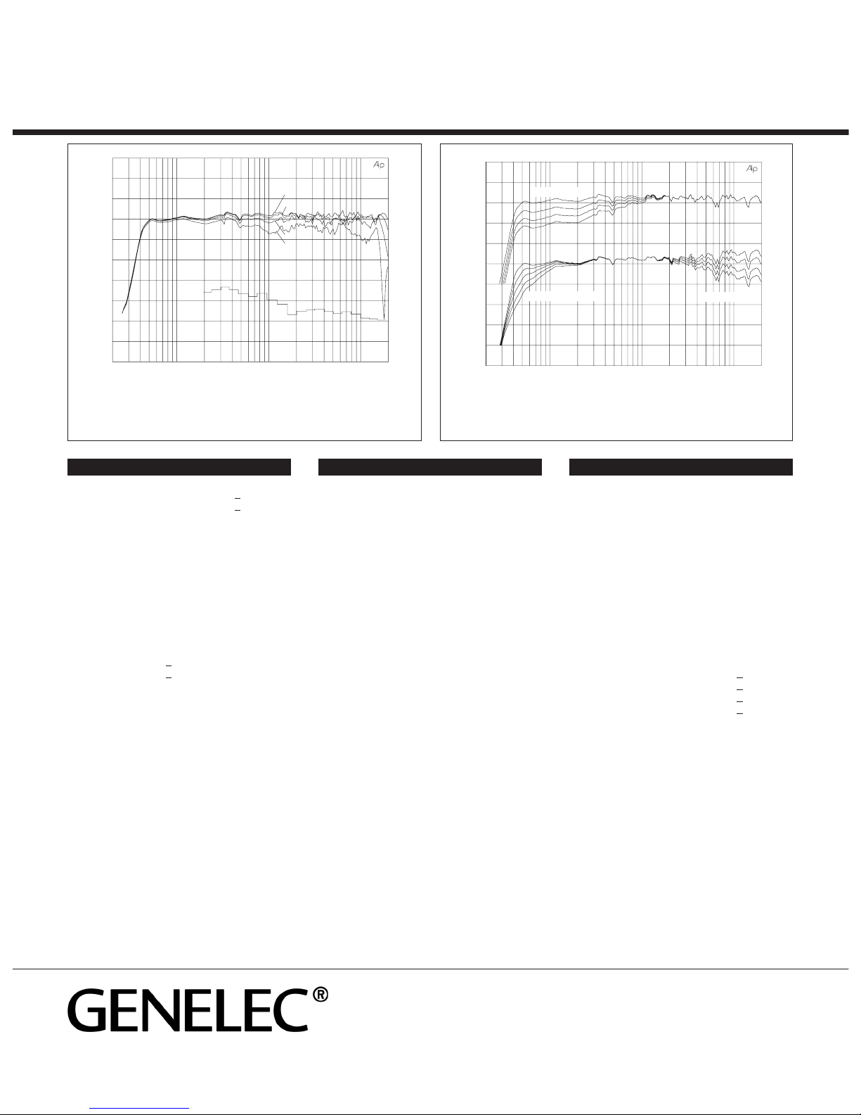
Figure 4. The upper curve group shows the horizontal directivity
characteristics of the 1032B in vertical configuration measured at 1 m.
The lower curve is a 1/3 octave band power response, measured in an
IEC approved reverberation chamber.
Figure 5. The upper curve group shows the effect of the bass tilt
control on the free field response. The lower curves show the effect
of the treble tilt and bass roll-off controls.
In China please contact:
Beijing Genelec Audio Co. Ltd.
Jianwai SOHO, Tower 12, Room 2605
39 East 3rd Ring Road
Chaoyang District
Beijing 100022, China
Phone +86 10 5869 7915, Fax +86 10 5869 7914
In Sweden please contact
Genelec Sverige
Ellipsvägen 10B
P.O. Box 5521, S-141 05 Huddinge
Phone +46 8 708 7070
Fax +46 8 708 7071
Email [email protected]
Table of contents
Other Genelec Speakers manuals

Genelec
Genelec 4020B User manual

Genelec
Genelec DSP 8260A User manual

Genelec
Genelec DSP 8260A Installation guide

Genelec
Genelec 4430A User manual

Genelec
Genelec 1038BC User manual

Genelec
Genelec G Three User manual

Genelec
Genelec 4436A User manual

Genelec
Genelec 1029A User manual

Genelec
Genelec 8350A User manual

Genelec
Genelec 1238CF User manual

Genelec
Genelec G One User manual

Genelec
Genelec 4420A User manual

Genelec
Genelec 8020A User manual

Genelec
Genelec AIW25 User manual

Genelec
Genelec SAM 1236A User manual

Genelec
Genelec 1031A User manual

Genelec
Genelec 4410A User manual

Genelec
Genelec 1032A User manual

Genelec
Genelec SAM 1238DF User manual

Genelec
Genelec aiw26b User manual


