General International 15-010S M1 Parts list manual

FEATURES
Tables can be adjusted up or down for full
belt use.
Front table can be inclined left or right.
Innovative hinged dust hood accommo-
dates oversized stock.
Easy adjustment of abrasive belt tension
with one lever only.
Graphite backing reduces belt friction for
longer belt life.
Single knob tracking control.
Auxiliary table allows curved sanding.
Heavy steel base ensures a solid stable
platform while sanding.
Dynamically balanced 7’’ rubber drive
roller and crowned 3’’ idler roller to ensure
solid belt tracking.
Oscillating feature.
SPECIFICATIONS
LENGTH OF OSCILLATION
UP: 1⁄8" (3.2 MM)
DOWN: 1⁄8" (3.2 MM)
TOTAL: 1/4" (6.4 MM)
BELT SIZE
6" X 108" (152 x 2743 MM)
FRONT TABLE SIZE (L X W)
7 3⁄4” x 37’’ (197 x 940 MM)
AUXILIARY TABLE SIZE(L X W)
11 3⁄4” x 19’’ (299 x 483 MM)
DUST CHUTE OUTLET
4" (102 MM)
BELT SPEED
3150 FPM
BASE DIMENSIONS (L X W)
42” x 16 1⁄2” (1067 x 419 MM)
MOTOR
M1 2 HP, 220 V, 1 PH, 10 A
M2 2 HP, 220 V, 3 PH, 6 A
M3 2 HP, 600 V, 3 PH, 3.7 A
WEIGHT
453 LBS (206 KG)
SETUP & OPERATION MANUAL
MODEL
#15-010S M1
6" X 108" VERTICAL OSCILLATING
REVISION 1 - September 16/08
© Copyright General® International 09/2008
EDGE BELT SANDER

THANK YOU
for choosing this General®International model 15-010S 6" X 108"
Oscillating Vertical Edge Belt Sander. This sander has been carefully tested and inspected
before shipment and if properly used and maintained, will provide you with years of reliable
service. To ensure optimum performance and trouble-free operation, and to get the most from
your investment, please take the time to read this manual before assembling, installing and
operating the unit.
The manual’s purpose is to familiarize you with the safe operation, basic function, and features
of this sander as well as the set-up, maintenance and identification of its parts and compo-
nents. This manual is not intended as a substitute for formal woodworking instruction, nor to
offer the user instruction in the craft of woodworking. If you are not sure about the safety of
performing a certain operation or procedure, do not proceed until you can confirm, from
knowledgeable and qualified sources, that it is safe to do so.
Once you’ve read through these instructions, keep this manual handy for future reference.
Disclaimer:
The information and specifications in this
manual pertain to the unit as it was supplied from the
factory at the time of printing. Because we are commit-
ted to making constant improvements, General®
International reserves the right to make changes to
components, parts or features of this unit as deemed
necessary, without prior notice and without obligation to
install any such changes on previously delivered units.
Reasonable care is taken at the factory to ensure that
the specifications and information in this manual corres-
ponds with that of the unit with which it was supplied.
However, special orders and “after factory” modifica-
tions may render some or all information in this manual
inapplicable to your machine. Further, as several gene-
rations of this model of sander and several versions of
this manual may be in circulation, if you own an earlier
or later version of this unit, this manual may not depict
your machine exactly. If you have any doubts or ques-
tions contact your retailer or our support line with the
model and serial number of your unit for clarification.
GENERAL® INTERNATIONAL
8360 Champ-d’Eau, Montreal (Quebec) Canada H1P 1Y3
Telephone (514) 326-1161 • Fax (514) 326-5555 • www.general.ca

GENERAL®& GENERAL®INTERNATIONAL WARRANTY
All component parts of General®, General® International and Excalibur by General
International ® products are carefully inspected during all stages of production and each unit
is thoroughly inspected upon completion of assembly.
Limited Lifetime Warranty
Because of our commitment to quality and customer satisfaction, General® and General®
International agree to repair or replace any part or component which upon examination,
proves to be defective in either workmanship or material to the original purchaser for the life
of the tool.
However, the Limited Lifetime Warranty does not cover any product used for profes-
sionnal or commercial production purposes nor for industrial or educational applications.
Such cases are covered by our Standard 2-year Limited Warranty only. The Limited Lifetime
Warranty is also subject to the “Conditions and Exceptions” as listed below.
Standard 2-Year Limited Warranty
All products not covered by our lifetime warranty including products used in commercial,
industrial and educational applications are warranted for a period of 2 years (24 months) from
the date of purchase. General® and General® International agree to repair or replace any
part or component which upon examination, proves to be defective in either workmanship or
material to the original purchaser during this 2-year warranty period, subject to the “conditions
and exceptions” as listed below.
To file a Claim
To file a claim under our Standard 2-year Limited Warranty or under our Limited Lifetime
Warranty, all defective parts, components or machinery must be returned freight or postage
prepaid to General® International, or to a nearby distributor, repair center or other location
designated by General® International. For further details call our service department at 1-888-
949-1161 or your local distributor for assistance when filing your claim.
Along with the return of the product being claimed for warranty, a copy of the original proof
of purchase and a “letter of claim” must be included (a warranty claim form can also be used
and can be obtained, upon request, from General® International or an authorized distributor)
clearly stating the model and serial number of the unit (if applicable) and including an expla-
nation of the complaint or presumed defect in material or workmanship.
CONDITIONS AND EXCEPTIONS:
This coverage is extended to the original purchaser only. Prior warranty registration is not
required but documented proof of purchase i.e. a copy of original sales invoice or receipt
showing the date and location of the purchase as well as the purchase price paid, must be
provided at the time of claim.
Warranty does not include failures, breakage or defects deemed after inspection by General®
or General® International to have been directly or indirectly caused by or resulting from:
improper use, or lack of or improper maintenance, misuse or abuse, negligence, accidents,
damage in handling or transport, or normal wear and tear of any generally considered con-
sumable parts or components.
Repairs made without the written consent of General® International
l
will void all warranty.

TABLE OF CONTENTS
SAFETY RULES . . . . . . . . . . . . . . . . . . . . . . .5
ELECTRICAL REQUIREMENTS . . . . . . . . . . . . . .6
Electrical connections . . . . . . . . . . . . . . . . . . . . . . .6
Grounding instructions . . . . . . . . . . . . . . . . . . . . . . .6
Circuit capacity . . . . . . . . . . . . . . . . . . . . . . . . . . . . .6
Check power connection for polarity . . . . . . . . . .6
Extension cords . . . . . . . . . . . . . . . . . . . . . . . . . . . . .6
IDENTIFICATION OF MAIN PARTS AND COMPO-
NENTS . . . . . . . . . . . . . . . . . . . . . . . . . . . .7
BASIC FUNCTIONS . . . . . . . . . . . . . . . . . . . .8
UNPACKING . . . . . . . . . . . . . . . . . . . . . . . .8
List of contents . . . . . . . . . . . . . . . . . . . . . . . . . . . . . .8
PLACEMENT WITHIN THE SHOP / ESTABLISHING
A SAFETY ZONE . . . . . . . . . . . . . . . . . . . . . . .9
LIFTING AND HANDLING THE MACHINE . . . . . . .9
ASSEMBLY INSTRUCTIONS . . . . . . . . . . . . . .10
Reposition the auxiliary table mounting bracket .10
Install the tables . . . . . . . . . . . . . . . . . . . . . . . . . . . .10
CONNECTING TO A DUST COLLECTOR . . . . . . .11
BASIC ADJUSTMENTS & CONTROLS . . . . . . . .11
Connecting to a power source . . . . . . . . . . . . . . .11
Magnetic safety switch . . . . . . . . . . . . . . . . . . . . . .11
Overload protection/Circuit breaker . . . . . . . . . .12
Front table height adjustment . . . . . . . . . . . . . . . .12
Front table inclination adjustment . . . . . . . . . . . .12
Auxiliary table height adjustment . . . . . . . . . . . . .13
Sanding belt tracking adjustment . . . . . . . . . . . . .13
MAINTENANCE . . . . . . . . . . . . . . . . . . . . . .14
Periodic maintenance . . . . . . . . . . . . . . . . .14
Required maintenance . . . . . . . . . . . . . . . .14
Replacement of the sanding belt . . . . . . . . . . . . .14
Replacement of the graphite coating on the
platen . . . . . . . . . . . . . . . . . . . . . . . . . . . . . . . . . . . .15
Steel platen adjustment . . . . . . . . . . . . . . . . . . . . .16
Timing belt tension adjustment/replacement . . .16
Lubrication . . . . . . . . . . . . . . . . . . . . . . . .17
Sanding belt tension mechanism . . . . . . . . . . . . .17
RECOMMENDED OPTIONAL ACCESSORIES . . . .17
PARTS LIST AND DIAGRAMS . . . . . . . . . . . . .18
CONTACT INFORMATION . . . . . . . . . . . . . . . .24

RULES FOR SAFE OPERATION
To help ensure safe operation, please take a moment to learn the machine’s applications and limitations, as well as poten-
tial hazards. General® International disclaims any real or implied warranty and holds itself harmless for any injury that
may result from improper use of its equipment.
1. Do not operate the sander when tired, distracted,
or under the effects of drugs, alcohol or any medi-
cation that impairs reflexes or alertness.
2. The working area should be well lit, clean and free
of debris.
3. Keep children and visitors at a safe distance when
the sander is in operation; do not permit them to
operate the sander.
4. Childproof and tamper proof your shop and all
machinery with locks, master electrical switches
and switch keys, to prevent unauthorized or unsu-
pervised use.
5. Stay alert! Give your work your undivided atten-
tion. Even a momentary distraction can lead to seri-
ous injury.
6. Fine particulate dust is a carcinogen that can be
hazardous to health. Work in a well-ventilated area
and wear eye, ear and respiratory protection
devices.
7. Do not operate this sander without an ade-
quate dust collection system properly installed and
running. Operating this sander without adequate
dust collection can lead to equipment malfunction
or dangerous situations for the operator or other
individuals in the workshop.
8. Do not wear loose clothing, gloves, bracelets, neck-
laces or other jewelry while the sander is in opera-
tion. Wear protective hair covering to contain long
hair and wear non-slip footwear.
9. Be sure that adjusting wrenches, tools, drinks and
other clutter are removed from the machine and/or
the feed table surface before operating.
10. Keep hands well away from the sanding belts and
all moving parts. Use a brush, not hands, to clear
away sanding dust.
11. Be sure sanding belts are securely installed on the
sanding drums.
12. Do not operate the sander if the sanding belts are
damaged or badly worn.
13. Do not push or force the workpiece into the sander.
The machine will perform better and more safely
when working at the feed rate for which it was
designed.
14. Avoid working from awkward or off balance posi-
tions. Do not overreach and keep both feet on floor.
15. To minimize risk of injury in the event of workpiece
kickback, never stand directly in-line with the sand-
ing belt or in the potential kickback path of the
work piece.
16. Keep guards in place and in working order. If a
guard must be removed for maintenance or clea-
ning, be sure it is properly re-attached before using
the tool again.
17. Never leave the machine unattended while it is run-
ning or with the power on.
18. Use of parts and accessories NOT recommended
by
GENERAL®INTERNATIONAL
may result in equip-
ment malfunction or risk of injury.
19. Never stand on the machine. Serious injury could
occur if the sander is tipped over or if the sanding
belt is unintentionally contacted.
20. Always disconnect the tool from the power source
before servicing, changing accessories or sanding
belts, or before performing any maintenance or
cleaning, or if the machine will be left unattended.
21. Make sure that switch is in “OFF” position before
plugging in the power cord.
22. Make sure the tool is properly grounded. If equip-
ped with a 3-prong plug it should be used with a
three-pole receptacle. Never remove the third
prong.
23. Do not use the sander for other than its inten-
ded use. If used for other purposes,
GENERAL®INTER
NATIONAL
disclaims any real implied warranty and
holds itself harmless for any injury, which may result
from that use.
5

ELECTRICAL CONNECTIONS
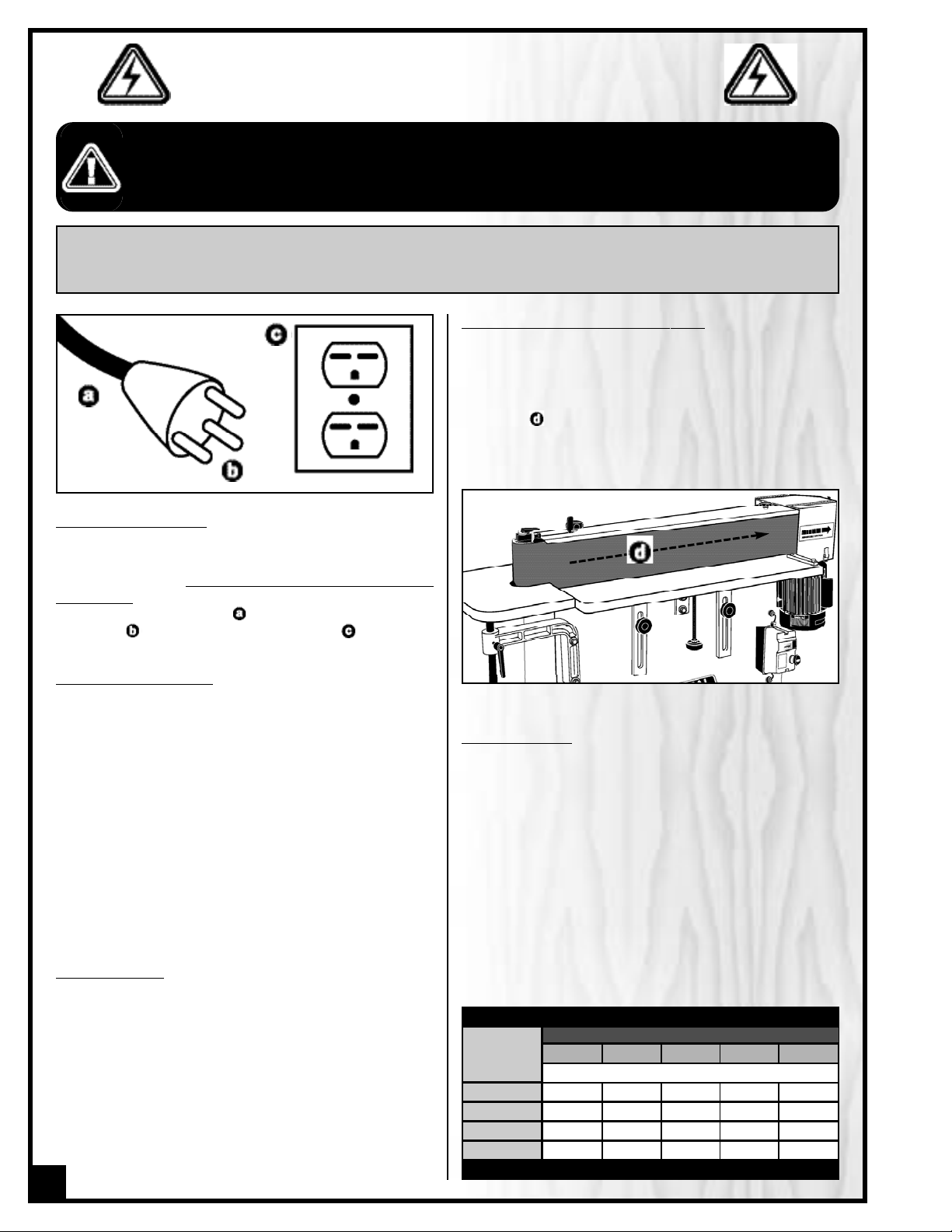
Both a manual circuit breaker (or similar device) as well
as an electrical plug (similar to the one shown) are re-
commended and should be installed by a qualified
electrician. Use locally approved wire that includes a
separate grounding wire , and a 3 prong grounding
type plug with a matching receptacle .
GROUNDING INSTRUCTIONS
In the event of an electrical malfunction or short circuit,
grounding reduces the risk of electric shock to the oper-
ator. The motor of the “M1” model of this machine is
wired for 220V single phase operation.As with many sta-
tionary industrial type machines, because each instal-
lation situation is unique, this sander is supplied without
a plug. The installation of an appropriate plug must be
performed by a qualified electrician. The machine must
be connected to an electrical source using a power
cord that has a grounding wire, which must also be
properly connected to the grounding prong on the
plug. The outlet must be properly installed and ground-
ed and all electrical connections must be made in
accordance with all local codes and regulations.
CIRCUIT CAPACITY
Make sure that the wires in your circuit are capable of
handling the amperage draw from your machine, as
well as any other machines that could be operating on
the same circuit. If you are unsure, consult a qualified
electrician. If the circuit breaker trips or the fuse blows
regularly, your machine may be operating on a circuit
that is close to its amperage draw capacity. However, if
an unusual amperage draw does not exist and a
power failure still occurs, contact a qualified technician
or our service department.
BEFORE CONNECTING THE MACHINE TO THE POWER SOURCE, VERIFY THAT THE VOLTAGE OF YOUR POWER SUPPLY CORRESPONDS
WITH THE VOLTAGE SPECIFIED ON THE MOTOR I.D. NAMEPLATE. A POWER SOURCE WITH GREATER VOLTAGE THAN NEEDED CAN
RESULT IN SERIOUS INJURY TO THE USER AS WELL AS DAMAGE TO THE MACHINE. IF IN DOUBT, CONTACT A QUALIFIED ELECTRICIAN
BEFORE CONNECTING TO THE POWER SOURCE.
THIS TOOL IS FOR INDOOR USE ONLY. DO NOT EXPOSE TO RAIN OR USE IN WET OR DAMP LOCATIONS.
CHECK POWER CONNECTION FOR POLARITY
After the wires have been connected it is necessary to
check if they are connected for proper polarity.
Press the start (green) button. The sanding belt should
move left to right as observed from the front of the
machine . If the sanding belt direction of rotation is
incorrect, press the stop (red) button and disconnect the
sander from power. Switch any two of the three wires at
L1, L2, L3 (for M2 and M3).
EXTENSION CORDS
The use of an extension cord is not generally recom-
mended for 220V equipment. If you find it necessary,
use only 3-wire extension cords that have 3-prong
grounding plug and a matching 3-pole receptacle that
accepts the tool’s plug. Repair or replace a damaged
extension cord or plug immediately.
Make sure the cord rating is suitable for the amperage
listed on the motor I.D. plate. An undersized cord will
cause a drop in line voltage resulting in loss of power
and overheating. The accompanying chart shows the
correct size extension cord to be used based on cord
length and motor I.D. plate amp rating. If in doubt, use
the next heavier gauge. The smaller the number, the
heavier the gauge.
6
NOTE: VOLTAGE REQUIREMENTS AND AMPERAGE DRAW FOR M2 & M3 3-PHASE MOTORS MAY NOT BE FULLY
DESCRIBED IN THIS MANUAL. FOR COMPLETE ELECTRICAL REQUIREMENTS REFER TO THE MOTOR I.D. NAME PLATE ON
THE MACHINE. IF IN DOUBT CONSULT A LICENSED QUALIFIED ELECTRICIAN BEFORE PROCEEDING.
ELECTRICAL REQUIREMENTS
TABLE - MINIMUM GAUGE FOR CORD
AMPERE
RATING
TOTAL LENGTH OF CORD IN FEET
220 VOLTS 50 FEET 100 FEET 200 FEET 300 FEET
AWG
< 5 -------> 18 16 16 14
6 TO 10 -------> 18 16 14 12
10 TO 12 -------> 16 16 14 12
12 TO 16 -------> 14 12 * NR * NR
* NR = Not Recommended

6" X 108" OSCILLATING VERTICAL
EDGE BELT SANDER
15-010S
IDENTIFICATION OF MAIN PARTS AND COMPONENTS
SANDING BELT TRACKING ADJUSTMENT
KNOB
LOCKING LEVER
SANDING BELT TENSION LEVER
TOP COVER
SANDING BELT
FRONT TABLE
END GUARD/DUST HOOD
MOTOR ASSEMBLY
ON/OFF SWITCH
FRONT TABLE HEIGHT ADUSTMENT KNOB
FRONT TABLE HEIGHT LOCK KNOBS
BASE
AUXILIARY TABLE HEIGHT ADJUSTMENT
LOCKING LEVER
AUXILIARY TABLE
7

UNPACKING
BASIC FUNCTIONS
This 6" x 108" vertical oscillating edge sander has been designed for sanding or polishing (removing kerf or pencil
marks) on small workpieces, such as chair legs or cabinet doors. This sander is not intended (and should not be
used) to sand any material other than wood. The front table can be inclined left or right for sanding irregular work-
pieces and the auxiliary/end table can be used for sanding round or curved surfaces. Both tables are height
adjustable, allowing you to use different sections of the belt depending on the height of the workpiece for an even
wearing of the sanding belt surface.
The oscillating feature allows for faster more efficient sanding. The cross grain sanding action caused by the oscil-
lation (vertical travel) of the belt optimizes sanding efficiency and extends sanding belt life by using a larger area
of the belts’ surface. Another advantage of the oscillating action of the belt is to help dissipate surface heat buildup
– as heat build-up can cause premature belt wear.
LIST OF CONTENTS QTY
SANDER..........................................................................1
FRONT TABLE
*
................................................................1
AUXILIARY TABLE
*
..........................................................1
TABLE HEIGHT ADJUSTIMENT KNOB..............................1
4 MM ALLEN KEY ...........................................................1
5 MM ALLEN KEY ...........................................................1
6 MM ALLEN KEY ...........................................................1
12 -14 MM OPEN END WRENCH ..................................1
8 - 10 MM OPEN END WRENCH ...................................1
* The front table and auxiliary table are stored inside the
sander cabinet to prevent damage in shipping. Unscrew
the 8 bolts using the 10 mm wrench supplied and remove
the back panel. Remove the tables from the cabinet and
reinstall the back panel, positioning it with the louvers
facing downward. (See picture below)
REAR VIEW
*
*
INSIDE VIEW
Carefully unpack and remove the sander and its components from the shipping crate and check for damaged or
missing items as per the list of contents below.
Note: Please report any damaged or missing items to your General International distributor immediately.
The plastic protective film on the front table must be
peeled off (see picture below).The plastic coating on the
auxiliary table is not to be removed.
8

PLACEMENT WITHIN THE SHOP /
ESTABLISHING A SAFETY ZONE
PLACEMENT WITHIN THE SHOP
This machine should be installed and operated only on a
solid, flat and stable floor that is able to support the
weight of the sander (453 lbs - 206 kgs) and the operator.
Using the dimensions shown as a guideline, plan for pla-
cement within your shop that will allow the operator to
work unencumbered and unobstructed by foot traffic
(either passing shop visitors or other shop workers) or
other tools or machinery.
ESTABLISHING A SAFETY ZONE
For shops with frequent visitors or multiple operators, it is
advisable to establish a safety zone around shop
machinery. A clearly defined “no-go” zone on the floor
around each machine can help avoid accidents that
could cause injury to either the operator or the shop visitor. It is advisable to take a few moments to either paint
(using non-slip paint) or using tape, define on the floor the limits or perimeter of each machines safety zone. Take
steps to ensure that all operators and shop visitors are aware that these areas are off limits whenever a machine is
running for everyone but the individual operating the unit.
LIFTING AND HANDLING THE MACHINE
A forklift with steel cable or a hydraulic hand pallet truck
will be required to lift the sander.
Note: Before lifting the sander, unscrew the hex head wood
screws securing the machine to it’s shipping crate , using
the supplied 14 mm open end wrench or a 14 mm socket
wrench.
The four 1/2” Hex. bolts and nuts are for bolting the sander
to the floor, for optional permanent installation.
SAFETY RULES FOR MACHINE LIFTING
1. Any equipment used to lift this machine should have
a rated capacity in excess of 453 lbs (206 kgs).
2. If using a steel cable, make sure it is strong enough
so it won’t break during the lifting.
3. The forklift must only be driven by a licensed driver.
4. The forks of forklift must protrude beyond the underside of the machine.
5. Pay special attention to the balance of the machine while lifting. (The motor side is much heavier)
6. Have another person help guide the way when lifting the machine.
7. Lower the machine slowly and carefully. Do not let the machine drop or jolt onto the floor.
THIS MODEL 15-010S SANDER IS VERY HEAVY.
TO LIMIT THE RISK OF SERIOUS INJURY OR DAMAGE TO THE MACHINE, READ AND FOLLOW ALL RECOMMENDATIONS BELOW.
9

ASSEMBLY INSTRUCTIONS
For your convenience this sander is shipped from the factory partially assembled and requires only minimal assem-
bly and set up before being put into service.
SERIOUS PERSONAL INJURY COULD OCCUR IF YOU CONNECT THE MACHINE TO THE POWER SOURCE BEFORE YOU HAVE COMPLE-
TED THE INSTALLATION AND ASSEMBLY STEPS. DO NOT CONNECT THE MACHINE TO THE POWER SOURCE UNTIL INSTRUCTED TO DO
SO.
1. Unscrew the upper bolt using the supplied 14
mm wrench and remove the auxiliary table moun-
ting bracket. Remove the lower bolt .
REPOSITION THE AUXILIARY TABLE MOUNTING BRACKET
Re-install the mounting bracket as shown in , with the
rubber pads against the sander.
REAR FACE VIEW
3. Install the front table on the front table moun-
ting bracket and re-install the two lock knobs to
secure the table in place.
2. Thread the table height adjustment knob into
the front table mounting bracket as shown in .
INSTALL THE TABLES
1. Remove the two lock knobs .
4. Insert the auxiliary table rod into the table
bracket as shown in .
10

CONNECTING TO A DUST COLLECTOR
DO NOT OPERATE THIS SANDER WITHOUT AN ADEQUATE DUST COLLECTION SYSTEM PROPERLY INSTALLED AND RUNNING.
OPERATING THIS SANDER WITHOUT ADEQUATE DUST COLLECTION CAN LEAD TO EQUIPMENT MALFUNCTION OR DANGEROUS
SITUATIONS FOR THE OPERATOR OR OTHER INDIVIDUALS IN THE WORKSHOP.
This sander is equipped with one 4" diameter dust outlet
, on the right side of the machine, allowing for connec-
tion to a dust collector (not included).
Be sure to use appropriate sized hose and fittings (not
included) and check that all connections are sealed
tightly to help minimize airborne dust.
Note: Minimum recommended dust collection CFM require-
ments for this sander is 1100 CFM.
If you do not already own a dust collection system
consider contacting your General® International dis-
tributor for information on our complete line of dust
collection systems and accessories or visit our Web Site
at www.general.ca.
BASIC ADJUSTMENTS & CONTROLS
CONNECTING TO A POWER SOURCE
Once the assembly steps have been completed plug the
power cord into an appropriate outlet. Refer back to the
section entitled “ELECTRICAL REQUIREMENTS” and make
sure all requirements and grounding instructions are fol-
lowed. When sanding operations have been completed
unplug the sander from the power source.
SWITCH OFF
MAGNETIC SAFETY SWITCH
This model 15-010S is equiped with a MAGNETIC SAFETY
SWITCH, located on the control box , designed to pro-
tect the unit and the user from power surges, power out-
ages and unwanted or unintentional start-up.
The switch assembly is equipped with a GREEN “START”
button and a RED spring loaded “STOP” button .
Once the RED “STOP” button has been pressed, the
machine can only be started by turning the BLACK inner
part of the button to the right to release the stop but-
ton.
ALWAYS TURN ON THE DUST COLLECTOR BEFORE START-
ING THE SANDER AND ALWAYS STOP THE SANDER
BEFORE TURNING OFF THE DUST COLLECTOR.
11
TO AVOID RISK OF SHOCK OR FIRE DO NOT OPERATE THE
UNIT WITH A DAMAGED POWER CORD OR PLUG. REPLACE
DAMAGED CORD OR PLUG IMMEDIATELY.
TO AVOID UNEXPECTED OR UNINTENTIONAL START-UP,
MAKE SURE THAT THE POWER SWITCH ON THE SANDER IS
IN THE OFF POSITION BEFORE CONNECTING TO A POWER
SOURCE.

OVERLOAD PROTECTION/CIRCUIT BREAKER
The magnetic safety switch on this sander is equipped with an overload protection feature. To prevent an electrical
overload from damaging the motor, in the event of a spike in line voltage or amperage draw, the internal overload
protector will automatically be tripped, thereby cutting off power to the motor.
To reset the overload protection switch after it has been tripped proceed as follows:
FRONT TABLE HEIGHT ADJUSTMENT
Adjusting the height of the table allows an even wearing
of the sanding belt surface by allowing you to use diffe-
rent sections of the belt depending on the height of the
workpiece. To raise or lower the table:
1. Loosen the two lock knobs then turn the height
adustment knob until the table is at the desired
height.
2. Tighten the two lock knobs to secure the table in posi-
tion.
Tip: To maximize belt usage when working with shorter
work pieces, periodically adjust the table height to sys-
tematically make use of various portions of the belt. For
example: a series of 2” tall workpieces can be separated
into 3 smaller batches with each batch being sanded
with the table set at different heights to use in sequence
the lower, middle or upper portion of the belt.
FRONT TABLE INCLINATION ADJUSTMENT
The front table can be inclined left or right for sanding
irregular workpieces.
1. Loosen the two lock knobs and raise or lower one
end of the table by hand either left or right .
2. Re-tighten the lock knobs to lock the table in position.
1. Set the power switch on the sander to the off posi-
tion and disconnect the machine from the
power source.
Note: If the sander is permanently connected to a cir-
cuit (hard-wired), set the wall panel circuit breaker or
main circuit interrupter to the off position.
2. Unscrew the 2 screws and remove the control
box front cover then press the red reset button .
3. Reinstall the control box cover.
4. Reconnect the sander to the power source.
5. You can now restart the sander by pushing on the
green button ON.
SWITCH OFF
TO AVOID UNEXPECTED OR UNINTENTIONAL START-UP BE CERTAIN THAT THE POWER SWITCH HAS BEEN SET TO THE OFF POSITION
BEFORE RE-SETTING THE CIRCUIT BREAKER.
12

13
AUXILIARY TABLE HEIGHT ADJUSTMENT
Adjusting the height of the auxiliary table allows an even
wearing of the sanding belt surface by allowing you to
use different sections of the belt depending on the height
of the workpiece.
1. Loosen the locking lever located on the auxiliary
table mounting bracket.
2. Raise or lower the auxiliary table by hand and
tighten the locking lever.
SANDING BELT TRACKING ADJUSTMENT
Though not essential, proper belt tracking (having the belt running straight and oscillating as evenly on the drums
as possible) can prolong belt life and avoid having the belt slip off during operation.
DO NOT ATTEMPT TO PERFORM ANY ADJUSTMENT WHILE THE MACHINE IS RUNNING. ALWAYS TURN OFF AND UNPLUG THE SANDER
BEFORE PERFORMING ANY ADJUSTMENT.
3. Pull the belt tension lever to the “loose” position.
4. Pull the belt tracking locking lever up to loosen
the belt tracking adjustment knob .
5. Turn the adjustment knob :
• Counter-clockwise to adjust the tracking upward;
• Clockwise to adjust the tracking downward.
6. Push the belt tension lever to the “tight” position .
7. Push the locking lever down to lock the belt
tracking adjustment knob
8. Turn on the machine for 5-10 seconds to visually
confirm the belt tracking.
9. As needed, repeat this adjustment process until the
belt is tracking evenly on the drums.
2. Turn the sander on for 5-10 seconds to visually con-
firm the belt tracking .
If the belt is not tracking straight, adjust as follows.
Loose Tight
1. Pull the belt tension lever to the “tight” position .
This sander is shipped from the factory with the sanding
belt already installed but not tightened. Set the belt ten-
sion lever to the “tight” position before turning on the
unit.

MAINTENANCE
MAKE SURE THE SANDER HAS BEEN TURNED OFF AND UNPLUGGED FROM THE POWER SOURCE BEFORE PERFORMING ANY
MAINTENANCE.
DO NOT OPERATE THE SANDER WITH A DAMAGED SWITCH, POWER CORD, PLUG, OR OTHER PARTS. REPLACE A DAMAGED PART
IMMEDIATELY.
• Keep the machine CLEAN and FREE OF DUST. Vacuum or brush off any loose debris and wipe down the machine
and the tables occasionally with a damp rag.
• Drums must always be kept clean. Dirt on drums will cause poor tracking and belt slippage.
• Periodically inspect the ON/OFF switch, power cord, plug and other parts for damage.
PERIODIC MAINTENANCE
REQUIRED MAINTENANCE
REPLACEMENT OF THE SANDING BELT
Sanding belt should be replaced when worn out.
Standard size (6" by 108") replacement belts can be purchased in a variety of grits from your General® International
dealer under the following parts numbers:
• #15-011 6” x 108” Sanding Belt 80 Grit
• #15-012 6” x 108” Sanding Belt 100 Grit
• #15-013 6” x 108” Sanding Belt 120 Grit
or (depending on availability) from your local tool, abrasives or sharpening supply dealer. These are standard sizes
that should be readily available in most areas. The use of any other size is not recommended and can lead to seri-
ous injury and/or damage to the machine.
Replace an installed, worn sanding belt as follows:
2. Flip the first section of the dust cover up , then flip
the entire cover back .
1. Unlock the two dust hood latches to access the
drive roller.
14

4. Pull the belt tension lever to the “loose” posi-
tion .
5. Remove the worn sanding belt . 6. Install a new sanding belt onto the drums .
Loose
Note: Belt tracking adjustments may be neces-
sary after changing or replacing a sanding
belt, to counterbalance for unevennesses be-
tween sanding belts. If needed, refer back to
section “Sanding Belt Tracking Adjustment”.
REPLACEMENT OF THE GRAPHITE COATING ON THE PLATEN
The graphite coating on the platen will wear and over
time require replacement. Every 3 years (approx.) in small
shop settings and up to 10 years in home shop settings,
the graphite coating will begin to show visible signs of
wear and will need to be peeled off (using a solvent
based stripper) and removed. A replacement graphite
coated paper strip should be glued (with contact
cement) onto the platen in it’s place.
Note: Most retail outlets that sell stationary power tools and
abrasives products do stock graphite replacement strips for
most popular sizes of sanders.
REAR VIEW
7. Reposition the belt tension lever back to the “tight”
position .
Tight
Tip: To extend belt life and avoid premature breakage, take note
of the direction arrows printed on the inside of the sanding
belt to make sure you install the belt in the correct direction.
3. Unscrew and remove the two lock knobs then
remove the top cover .
15

STEEL PLATEN ADJUSTMENT
The steel platen should protrude 1/8” to 1/4” (approx.)
past the motor drive roller and idle roller in order to
be in complete contact with the abrasive belt.
The steel platen is initially set at the factory but, due to
vibrations, over time, may need to be re-adjusted.
1. Turn off and unplug the sander from the power source.
2. Remove the sanding belt. If needed, refer back to
section “Replacement of the sanding belt”.
3. Use a straightedge or a combination square to mea-
sure the clearance between the steel platen and the
drive roller , and between the steel platen and the
idle roller . If the width of the gaps is more than 1/8”
to 1/4” (approx.) or if the width of both gaps is not
the more or less the same, re-adjust the steel platen as
follows:
4. Loosen the two hex head bolts using the supplied 14
mm wrench or a 14 mm socket wrench, then tap on
one or both sides of the steel platen to move it either for
ward or backward until you obtain a gap of 1/8” to
1/4” (approx.) between the steel platen and each of
the two rollers.
5. Retighten the two hex head bolts then reinstall the
sanding belt.
LEFT SIDE VIEW RIGHT SIDE VIEW
1/8” – 1/4”
LARGER VIEW
TIMING BELT TENSION ADJUSTMENT/REPLACEMENT
With usage and wear over time, the timing belts that trans-
fer power from the motor shaft to the drive roller may
require tension adjustment. Loose timing belts will cause
the drive roller and/or the oscillation to function intermit-
tently and may cause excessive noise or vibration. In such
cases the timing belts can be tensioned as follows:
1. Loosen the two hex nuts .
2. Turn the bolt clockwise then retighten the two hex
nuts.
Note: Turn the bolt in 1 turn increments, recheck and adjust again as needed.
Should timing belt breakage occur, remove the 4 bolts , under the motor assembly bottom cover to access and
replace the belt(s).
16

LUBRICATION
SANDING BELT TENSION MECHANISM
Keep the sanding belt tension mechanism (located at
the rear of the sander, under the tension lever) well lubri-
cated and free of dust or debris. Clean and remove dust,
debris, and old lubricant every 6 months or as needed
depending on frequency of use. After cleaning, reapply
lubricant as needed.
Note: Use any all-purpose grease, available at any hardware
store).
NOTE: The motor and all bearings are sealed and permanently lubricated – no further lubrication is required.
17
Notes
RECOMMENDED OPTIONAL ACCESSORIES
Here are some of the optional accessories available from your local General International dealer.
For more information about our products, please visit our website at www.general.ca
SANDING BELTS
STANDARD SIZE
(6" BY 108")
#15-011 - 80 Grit
#15-012 - 100 Grit
#15-013 - 120 Grit
DUST COLLECTORS
Dust collectors contribute to
a cleaner more healthful
workshop environment.
We offer a wide selection of
top quality dust collectors to
suit all your shop needs.

43
42
52
51
03
78
06
20
05
08
07
59
86
03
83
39
81
07
21
41
45
72
73
75
74
18
85
70
68
70
179
12
07
02
01
SAFETY RULES
172
33
32
80
21
190
27
45
22
07
46
159
163
90
89
185
160
161
162
91
92
191
181
180
178
177
174
173
167
168
171
170
169
168
167
166
165
164
175
176
183
88
150
148
99
151
70
152
59
19
154
156
157
158
149
187
188
07
66
196
195
194
193
192
70
64
189
61
186
MAIN ASSEMBLY
18

71
184
99
63
53
56
93
94
97
50
182
101
102
95
100
118
117
103
104
105
106
119
120
121
122
123
124
125
126
127
123
120
115
114
116
113
99
112
146
147
129
128
109
145
144
143 142 141
140
139
130
131
132
133
122
138
134
135
136
137
124
107
108
109
110
111
130
131
132
133
96
98
99
49
19
MOTOR ASSEMBLY

20
PARTS LIST
15-010S
PART NO. DESCRIPTION SPECIFICATION QTY
15010-01 AUXILIARY TABLE 1
15010-02 END STEEL PLATE 1
15010-03 SELF-TAPPING SCREW 8
15010-05 TABLE MOUNTING BRACKET 1
15010-06 LOCK KNOB 1/2”-12NCX25X61 2
15010-07 WASHER 3/8”X20X2 24
15010-08 HEX HEAD BOLT 3/8”-16NCX2-1/2” 2
15010-12 HEX NUT 3/8”-16NC 19
15010-18 FRONT TABLE 1
15010-19 FRONT STEEL PLATE 1
15010-20 TABLE SUPPORT 2
15010-21 HEX HEAD BOLT 3/8”-16UNC*1” 9
15010-22 HEX HEAD BOLT 3/8- 16UNC*5/8” 2
15010-27 LOCK KNOB 5/16”-18NC*18*38 2
15010-32 SANDING BELT 1
15010-33 TOP COVER SUPPORT 2
15010-39 FRONT TABLE MOUNTING BRACKET 1
15010-41 TABLE HEIGHT ADJUSTING KNOB 1/2”-12NCX200X61 1
15010-42 HEX HEAD BOLT 1/4”-20UNC-3/8’ 8
15010-43 FLAT WASHER 8
15010-45 FLAT WASHER 4
15010-46 BACK PANEL 1
15010-49 SOCKET HEAD BOLT 1
15010-50 DRIVE ROLLER 1
15010-51 HEX HEAD BOLT 1/2”-12UNCX6” 4
15010-52 HEX NUT 1/2”-12UNC 4
15010-53 SET SCREW 5/16” 1
15010-56 KEY 7X7X70 1
15010-59 FLAT WASHER 8
15010-61 ROUND HEAD BOLT M4 X0.7 2
15010-63 FLAT WASHER 1
15010-64 POWER CORD 1
15010S-66 WARNING LABEL 1
15010-68 NAME PLATE 1
15010-70 STRAIN RELIEF 4
15010-71 LABEL 1
15010-72 STOP 1
15010-73 HEX HEAD BOLT 5/16”-18UNCX2-1/2” 2
15010-74 WASHER 5/16”X23X2T 2
15010-75 HEX NUT 5/16”-18UNC 6
15010-78 FLAT WASHER 1/2”X32MMX3T 2
15010-80 FLAT WASHER 3/8”X23MMX3T 2
15010-81 HEX HEAD BOLT 3/8"-16UNCX1” 4
15010-83 RUBBER PAD 39MMX29X3T 2
15010-85 SPACER 1
15010-86 LOCKING LEVER 1/2” –12UNCX30MM 1
15010S-88 HEX HEAD BOLT 3/8”X5” 2
15010S-89 LOCKING LEVER 1
15010S-90 MICRO ADJUST SPRING 1
15010S-91 MICRO ADJUST RING 1
15010S-92 MICRO ADJUST SCREW 1
15010S-93 NYLON NUT M24 X3.0P 1
15010S-94 RING 1
15010S-95 BRACKET 1
15010S-96 SHAFT 1
15010S-97 MOTOR PLATE 1
15010S-98 FLAT WASHER D8.2XD23X2T 4
15010S-99 LOCK WASHER 4
Table of contents
Other General International Sander manuals

General International
General International 15-155 M1 Parts list manual

General International
General International 15-142 M1 Parts list manual

General International
General International BD7004 Parts list manual

General International
General International 15-030 M1 Parts list manual

General International
General International 15-150 MI Parts list manual

General International
General International 15-035 MI Parts list manual