GENERAL RADIO COMPANY 1231-B User manual

OPERATING
INSTRUCTIONS
TYPE
1231-B
AMPLIFIER
AND
NULL
DETECTOR
GENERAL
RADIO
COMPANY

OPERATING INSTRUCTIONS
TYPE
1231-B
AMPLIFIER
AND
NULL
DETECTOR
Form 634-H
May,
1961
GENERAL
RADIO
COMPANY
WEST
CONCORD,
MASSACHUSETTS,
USA

TABLE OF CONTENTS
Section
1. INTRODUCTION •
1.1
Purpose
.
1.2
Description.
1.2.1
General
1.2.2
Controls
1.2.3
Connections
1.2.4
Accessories
.
Section 2. PRINCIPLES OF OPERATION.
2.1
General
.
2.2
Linear
Amplifier
.
2.3
Semilogaritlunic
Null
Detector
2.4
Use
with
Type
874-LBA
Slotted
Line
2.5
Frequency
Response.
1
1
1
1
1
2
3
3
3
3
3
4
4
Section 3. INSTALLATION 4
3.1
Battery
. 4
3.2
A-C
Power
Supply. 4
3.3
Relay-Rack
Model 5
Section 4. OPERATING PROCEDURE. 6
4.1
General
. 6
4.2
Use
as
an
Amplifier
. 6
4.3
Use
as
a Null
Detector
6
4.4
Operation
as
Standing-Wave
Indicator
• 6
4.4.1
Frequency
Selection
. 6
4.4.2
Test
for
Adequate
R-F
Input
for
Low VSWR
Measurement
Assuming
50%
Modulation. 7
4.4.3
Measuring
Standing-Wave
Ratio
7
Section 5. ACCESSORIES 7
5.1
Tuned
Circuits.
7
5.2
Adjustable
Attenuator
9
5.3
Adjustable
Filter
. 9
Section 6. SERVICE
AND
MAINTENANCE . 12
6.1
General
.
6.2
Cabinet
Removal
6.3
Tube
Voltages
and
Resistance
Measurements
6.4
Zero
Coincidence.
6.5
Meter
Sensitivity
.
PARTS LIST
12
12
12
12
12
14

SPECIFICATIONS
TYPE
1231-B AMPLIFIER
AND
NULL DETECTOR
Input Impedance: 1 megohm
in
parallel with
20J.Lj.Lf;
alternate
10-megohm input
available.
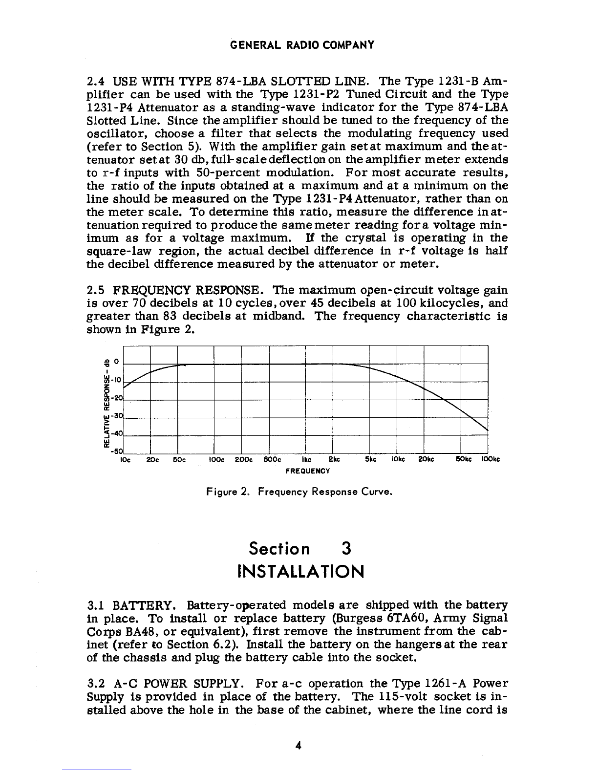
Maximum Gain: Greater than 83
db
at
1
kc
with 1-megohm load.
Meter
Scales:
NORM
scale,
calibrated
in
volts
with
accuracy
of ±5%
of
full
scale;
SENS
scale,
calibrated
in
db
with arbitrary zero.
DB
ratios
accurate
within
30%
of
correct
value
in
db, if one reading is above holf
scale.
Null-Detector
Sensitivity:
Less
than
25J.Lv
input
gives
1%
indication
on
meter
at
1 kc.
Amplifier
Sensitivity:
Less
than
8j.Lv
input
at
1 kc for
1%
indication on SENS range
of
meter.
Output Impedance: Approximately 50,000 ohms.
Maximum Output Voltage: 5
volts
into 20,000 ohms; 20
volts
into one megohm.
Open-Circuit Noise and
Hum
Level:
Less
than
0.5
volt
at
full gain, battery operated;
less
than
one
volt, a-c operated with
Type
1261-A Power Supply.
Battery
Life: 200 to 250 hours
at
8 hours a day.
Dimensions: Height, 8 in.; width,
12-1/4
in.; depth,
10-3/4
in.; over-all.
Weight:
23-3/4
pounds, including
batteries,
{cabinet model).
TYPES
1231·P2
AND
-P3
TUNED CIRCUITS
Tuning
Accuracy:
±2%
at
normal
voltage
levels.
Attenuation: At
least
25 db to second harmonic.
Dimensions: Height,
4-1/8
in.; width,
3-9/16
in.; depth, 4 in.; over-all.
Weight:
3-7/8
pounds.
TYPE
1231-P4 ADJUSTABLE ATTENUATOR
Source Impedance: 30 kfl, about equal
to
output impedance of
crystal
detector
in
slotted
line.
Lood Impedance: At
least
1 megohm.
Insertion
Loss:
3 db.
Attenuation Range: 80 db,
readable
to
nearest
tenth db.
Attenuation
Accuracy:
±0.3
db when
operated
between
rated
source
and load impedances.
Additional
errors
caused
by
source
between
14
kfl and
60
kfl
are
less
than
±0.3
db.
Frequency
Error: Negligible below 2 kc.
Maximum Input Power:
1/2
watt.
Terminals:
Input,
Type
938-W
Binding
Posts;
output,
shielded
cable
with
Type
274-NK
shielded
plug to fit
Type
1231-B input terminals.
Accessories
Required: One
Type
874-R34
Patch
Cord for
connections
between
slotted
Iine and attenuator.
Dimensions: Height,
4-1/2
in.; width,
5-1/2
in.; depth,
5-1/2
in.; over-all.
Weight: 2 pounds,
11
ounces.

Figuro I, Typo 1
23
1
-B
Amp
lilior and
Nu
ll Ootoctar.
SPEC
I
FICATIONS
<COHT)
TYPE 1231.P5
ADJUSTABLE
Fll
TER
Fr•queney Collbratlon: 50, 100, 200, 500
cps,
1,
2,
5,
10, 20,
SO
,
100
kc.
%2%
ot
minimum
voltogu.
lnurtlon
Gain:
.7
to +15 db, depending upon ftoquoncy. Soeond·hormonic rojoction: 28
to
46
db.
Termlnols: Shielded cord and plug
for
connection
to
Typo 1231
·6
jock·top terminals for
external
capac
it
or
s.
Acceuorln
Availabl
e:
Type 219 Decode
Copoeitou
for
tuning
filter betwoon frequencies
provided.
Di
me
nsions:
Front P
anel:
h
eig
ht,
7
in.;
width,
6-1/8
in,,
Cabinet: depth,
9-3/4
in.
Inte
rn
al shiold box: hoight, 6-1/A in
.;
width,
4-1/2
in
.;
depth, 9 in.
W•lght: 9 poun
ds,
12
ounces.

TYPE
1231-B
AMPLIFIER
AND
NULL
DETECTOR
Section 1
INTRODUCTION
1.1 PURPOSE.
The
Type
1231-B
Amplifier
and
Null
Detector
(Figure
1)
is
designed
for
use
asa
high-gainamplifier,
as
asensitive
nullindicator
for
bridge
measurements,
and
as
a
standing-wave
indicator
for
measure-
ments
with
the
Type
87
4-
LBA
Slotted
Line.
Used
with
a
suitable
crystal
detector,
it
will
indicate
amplitude-modulated
high-frequency
voltages,
and
is
also
useful
as
a
preamplifier
for
crystal
microphones,
vibration
pickups,
and
oscilloscopes.
1.2 DESCRIPTION.
1.2.1 GENERAL.
The
Type1231-BAmplifierand
Null
Detector
is
avail-
able
in
cabinet
and
relay-
rack
models,
operated
by
either
a
battery
(Burgess
6TA60,
Army
Signal
Corps
BA48)
or
an
a-c
power
supply
(Type
1261-A
Power
Supply).
Type
numbers
used
todesignatethevarious
mod-
els
are
indicated
below:
1231-BM
Cabinet
model,
battery
operated
1231-BMA
Cabinet
model,
a-c
operated
1231-BR
Relay-rack
model,
battery
operated
1231-BRA
Relay-rack
model,
a-c
operated
1231-BRF
Relay-rack
model,
battery
operated
with
Type
1231-PS
Filter
1231-BRFA
Relay-rack
model,
a-c
operated
with
Type
1231-PS
Filter
1.2.2
CONTROLS.
The
following
controls
are
on
the
panel
of
the
Type
1231-
B
Amplifier
and
Null
Detector:
1

GENERAL
RADIO
COMPANY
Name
Type
FuncUon
GAIN
Continuous
Varies
gain
of
amplifier
or
rotary
control
sensitivity
of
null
detector.
ZERO
Cap-covered
Makes
the
zero
of
the
SENS
COINCIDENCE
screw-driver
meter
range
coincide
with
the
adjustment
zeros
of
the
NORM
meter
ranges
and
the
null
detector.
ZERO
SET
Continuous
Sets
electrical
zero
at
meter
rotary
control
zero.
AMPL
METER
Push
buttons
(2)
Provide
choice
of
range
for
linear
amplifier
operation:
NORM
range
for
monitoring
output
during
amplifier
oper-
ation,
SENS
range
for
input
voltages
too low
for
NORM
range
or
NULL
DETECTOR.
NULL
Push
button
Causes
output
stage
to
function
DETECTOR
as
a
logarithmic
amplifier
for
null-detector
operation.
BATT CHECK
Push
buttons
(2)
Check
condition
of
the
plate
and
filament
batteries.
OFF
Push
button
Turns
off
battery
power
supply.
INPUT
Push
buttons
(2)
~0.03
v -
sets
approximate
maximum
no-load
gain
at
85
decibels
with
maximum
input
voltage
of
less
than
0.
03
volt.
<1
v -
sets
approximate
maximum
no-load
gain
at
55
decibels
with
maximum
in-
put
voltage
of
less
than
1
volt.
1MO-
10MO
Toggle
switch
Selects
input
impedance
of
the
amplifier.
1.2.3
CONNECTIONS.
The
following
connections
are
on
the
pane1of
the
Type
1231-B
Amplifier
and
Null
Detector:
Name
Type
Function
INPUT
Jack-top
binding
posts
(2) Input
terminals.
FILTER
Telephone
jack
Provides
for
connecting
a
filter
to
the
output
stage
of
the
instrument.
OUTPUT
Jack-top
binding
posts
(2) Output
terminals.
2

TYPE
1231-B
AMPLIFIER AND NULL DETECTOR
1.2.4
ACCESSORIES.
The
following
table
lists
accessories
supplied
with
the
various
models
of
the
Type
1231-B
Amplifier
and
Null
Detector:
Type
Accessories
Supplied
1231-BM
Cabinet
1231-BMA
Cabinet,
Type
1261-A
Power
Supply
1231-BR
Type
1231-
P7
Connecting
Panel
1231-BRA
Type
1261-A
Power
Supply,
Type
1231-P7
Connecting
Panel
1231-BRF
Type
1231-P5R
Filter
1231-BRFA
Type
1261-A
Power
Supply,
Type
1231-P5
Filter,
Type
1231-
P6
Connecting
Panel*
*for
Type
1610-A
Capacitance
Measuring
Assembly,
use
Type
1231-P6-2
Connecting
Panel
Section 2
PRINCIPLES
OF OPERATION
2.1 GENERAL.
The
simplified
circuit
diagram
(Figure
7)
shows
that
the
amplifier
has
three
stages
and
a
built-in
vacuum-tube
voltmeter,
which
consists
of a
diode
rectifier,
a
d-e
amplifier,
and
the
panel
meter.
2.2
LINEAR AMPLIFIER.
During
linear-amplifier
operation,
there
is
a
choice
of
maximum
no-load
gain
of 55
or
85
decibels,
as
selected
by
the
input
attenuator
buttons
at
<1
volt
or
<
0.03
volt
respectively.
A
tapered
wire-wound
gain
control
allows
continuous
variation
of
the
gain
over
a
wide
range.
2. 3 SEMILOGARITHMIC NULL
DETECTOR.
During
semilogarithmic
null-detector
operation,
rectified
de
from
the
vacuum
-tube
voltmeter
diode
is
applied
as
gain-controlling
bias
to
the
last
amplifier
stage
to
produce
the
desired
characteristics.
An
attenuator
in
the
grid
circuit
allows
meter
current
to
be
zero
with
no
signal
at
the
instrument
ter-
minals.
3

GENERAL RADIO COMPANY
2.4
USE WITH TYPE 874-LBA SLOTTED LINE.
The
Type
1231-B Am-
plifier
can
be
used
with
the
Type 1231-P2
Tuned
Circuit
and
the
Type
1231-
P4
Attenuator
as
a
standing-wave
indicator
for
the
Type
874-
LBA
Slotted Line. Since
the
amplifier
should
be
tuned
to
the
frequency
of
the
oscillator,
choose
a
filter
that
selects
the
modulating
frequency
used
(refer
to
Section 5).
Wit.'1
the
amplifier
gain
setat
maximum
and
theat-
tenuator
set
at
30 db,
full-scale
deflection
on
the
amplifier
meter
extends
to
r-f
inputs
with
50-percent
modulation.
For
most
accurate
results,
the
ratio
of
the
inputs
obtained
at
a
maximum
and
at
a
minimum
on
the
line
should
be
measured
on
the
Type
1231-
P4
Attenuator,
rather
than
on
the
meter
scale.
To
determine
this
ratio,
measure
the
difference
in
at-
tenuation
required
to
produce
the
same
meter
reading
for
a
voltage
min-
imum
as
for
a
voltage
maximum.
If
the
crystal
is
operating
in
the
square-law
region,
the
actual
decibel
difference
in
r-f
voltage
is
half
the
decibel
difference
measured
by
the
attenuator
or
meter.
2.5 FREQUENCY RESPONSE.
The
maximum
open-circuit
voltage
gain
is
over
70
decibels
at
10
cycles,
over
45
decibels
at
100
kilocycles,
and
greater
than 83
decibels
at
midband.
The
frequency
characteristic
is
shown
in
Figure
2.
~
0
I
lll-1
0/
~-20
"'
a:
OJ•3
>
j::
5·40
II!
·5
0
.....-
IOc
20c
SOc
-~---~
.........
""-
"""",
""'
IOOc
200c 500c
Ike
2kc 5kc
IOkc
20kc 50kc
IOOkc
FREQUENCY
Figure
2.
Frequency
Response
Curve.
Section
3
INSTALLATION
3.1 BATTERY.
Battery-operated
models
are
shipped
with
the
battery
in
place.
To
install
or
replace
battery
(Burgess
6TA60,
Army
Signal
Corps
BA48,
or
equivalent),
first
remove
the
instrument
from
the
cab-
inet
(refer
to Section 6.2).
Install
the
battery
on
the
hangers
at
the
rear
of
the
chassis
and
plug
the
battery
cable
into
the
socket.
3.2 A-C POWER SUPPLY.
For
a-c
operation
the
Type 1261-A
Power
Supply
is
provided
in
place
of
the
battery.
The
115-volt
socket
is
in-
stalled
above
the
hole
in
the
base
of
the
cabinet,
where
the
line
cord
is
4

TYPE
1231-B AMPLIFIER
AND
NULL DETECTOR
inserted.
The
panel
switch
of
the
instrument
must
be
left
ON
and
the
switch
in
the
line
cord
used
to
turn
the
power
supply
ON
and
OFF.
With
both
the
panel
switch
and
line
cord
switch
ON,
measure
the
filament
volt·
age
by
pushing
the
F
IL
button. Note
the
meter
reading.
Push the button
on top
of
the
power
supply
and
again
note
the
meter
reading.
Tum
the
screw
-
driver
adjustment
on top
of
the
power
supply
until both
meter
readings
are
equal.
To
keep
the
hum
level
low,
do
not
ground
the
case
of
the
power
supply
to
the
instrument
shield.
3.3 RELAY-RACK MODEL.
The
Type
1231
·P7
Connecting
Panel
is
in-
stalled
to
fit
the
standard
19-ln.
relay-rack
. Whenthe Type 1231-PSAd-
justable
Filter
is
included,
the
Type
1231-P6
Connecting
Panel
Is
used.
(See F
lgure
3.)
Figure 3o. Typo 1231-P7 Connecting Panel.
Figure
3b.
Type 1231-P6 Connecti
ng
Panel
and Type 1231-PS Filter.
5

GENERAL RADIO COMPANY
Section 4
OPERATING
PROCEDURE
4.1 GENERAL.
The
following
procedure
should
be
followed
when
the
Type
1231-B
is
first
set
up.
a.
Turn
the
power
on
by
pushing
either
the
NULL
DET
button
or
one
of
the
AMPL
METER
buttons.
b.
Zero
the
meter
by
turning
the
ZERO
SET
knob
with
the
INPUT
terminals
short-circuited.
If
the
zero
of
the
SENS
range
does
not
coin-
cide
with
the
zero
of
the
NORM
and
NULL
DET
ranges,
remove
the
ZERO
COINCIDENCE
cap
and
set
the
screw-
driver
adjustment
until
there
is
no
change
in
meter
indication
as
the
meter
is
switched
between
the
SENS
and
NORM
ranges.
c.
To
check
the
battery,
push
the
BATT CHECK PL
and
FIL
but-
tons,
and
note
the
meter
indications.
If
the
indication
with
either
button
pushed
is
below
the
BATT
mark
on
the
meter,
replace
the
battery.
d.
Select
the
input
impedance
by
means
of
the
1
MQ
-10
MQ
switch.
4.2
USE
AS
AN
AMPLIFIER.
For
ordinary
use,
operate
with
the
NORM
button
pushed;
then
meter
deflection
is
approximately
linear,
and
full
scale
corresponds
to
20
volts.
When
the
input
voltage
is
too
low
to
give
satisfactory
meter
indications,
operate
with
the
SENS
button
pushed.
The
meter
deflection
is
approximately
linear,
and
full
scale
corresponds
to
2
volts.
4.3
USE
AS
A NULL DETECTOR. When
using
the
Type
1231-B
as
a
null
detector
first
remove
all
load
from
the
OUTPUT
terminals.
Then
select
maximum
no-loadgain
by
means
of
the
INPUT
attenuator
buttons.
With
the
<:
1 v
button
pushed,
maximum
no-load
gain
is
55 db. With
the
< 0.03 v button
pushed,
maximum
no-load
gain
is
85
db
and
the
meter
is
more
sensitive.
Increasing
the
gain
setting
also
increases
sensitivity.
Use
the
NULL
DET
button
for
preliminary
balances,
the
SENS
but-
ton
for
final
balance.
4.4
OPERATION
AS
STANDING-WAVEINDICATOR.
(Refer
to
Operating
Instructions
for
Type
87
4-
LBA
Slotted
Line.)
4.4.1 FREQUENCY SELECTION.
Tune
the
amplifier
to
the
modulation
frequency
with
an
appropriate
filter
(refer
to
Section
5).
6

TYPE 1231-B AMPLIFIER
AND
NULL DETECTOR
4.4.2
TEST
FOR
ADEQUATE
R-F
INPUT
FOR
LOW VSWR MEASURE-
MENT
ASSUMING 50% MODULATION.
a.
Find
the
voltage
maximum
on
the
line.
b.
Set
the
Type
1231-B
for
maximum
sensitivity
and
set
the
Type
1231-
P4
Attenuator
for
attenuation
less
than
30
db.
c.
Find
the
voltage
minimum
on
the
line.
d.
If
the
meter
reading
at
the
minimum
is
greater
than
one-fourth
of
full
scale,
the
r-f
input
to
the
line
is
adequate.
If
the
meter
reading
is
less
than
one-fourth
of
full-scale,
increase
the
r-f
input
or
the
probe
coupling.
4.4.3
MEASURING STANDING-WAVE RATIO.
For
most
accurate
re-
sults,
the
ratio
of
the
outputs
obtained
at
a
maximum
and
at
a
minimum
on
the
line
should
be
measured
on
the
Type
1231-P4
Attenuator,
rather
than
on
the
meter
scale.
a.
At
the
voltage
maximum,
note
the
attenuation
and
the
ampli-
fier
meter
reading.
b.
At
the
voltage
minimum,
vary
the
attenuation
of
the
Type
1231-
P4
Attenuator
until
the
amplifier
meter
reading
is
the
same
as
that
noted
in
step
a.
c.
If
the
crystal
is
operating
in
the
linear
region,
the
difference
in
attenuation
at
these
two
points
is
the
standing-wave
ratio
(SWR =20
E
log
10
Em~x)
expressed
in
decibels.
m1n
d.
If
the
crystal
is
operating
in
the
square-law
region,
the
actual
db
difference
in
r-f
voltage
is
half
of
the
db
difference
measured.
Section
5
ACCESSORIES
5.1 TUNED CffiCUITS.
Types
1231-P2 (400
and
1000
cycles)
and
-P3
(60
cycles)
Tuned
Circuits
(Figure
4)
can
be
used
as
interstage
filters
with
the
Type
1231-B
for
suppressing
harmonics,
noise,
and
hum
in
sin-
gle-frequency
measurements.
A
telephone
plug
on
each
filter
plugs
into
a
panel
jack
on
the
Type
1231-B
Amplifier
and
Null
Detector.
Filters
thus
connected
are
isolated
by
amplifier
stages
from
the
effects
of
vary-
ing
input
and
output
impedances
and
at
the
same
time
are
at
a
high
7

0
1/1
I0
..J
llj
0
~
20
!':
i5
30
Si
~
1-
4 0
!<i
50
/
GENERAL RADIO COMPANY
Figure 4.
Ty
pe
123
l.P3 Tuned Circuil
(ldenli
ca
l
in
A
pp
earance
ro
Typo 123l.P2).
TVI'E
TVPE
1231-
P3
1231
·
P2
J \
~
\
I 1/ -\
1/ v /
'\
1'\.
1- v
r-/
"'
""'
v /
""'
1'.::::
-
K
10
20
50
1
00
200
500
1
,000
2POO
5poo
10,000
FREQUENCY
IN
CYCLES
PER
SECOND
FigureS
. Attenuation Curve, T
yp
es
12
31
-P2
and
-P3
Tunod
Circ
uit
s.
enou
gh
voltage
l
evel
along
the
amplifyin
g
chain
to
withstand
effects
of
external
fields.
Figure
5
shows
the
attenuation
vs
frequency
for
the
Types
1
23l
·P2
and
·P3 TUned
Circuits.
5.2
ADJUSTABLE ATIENUATOR. When
used
with
the
Typel231-B
am·
p
ll
fier
and Null
Detector
and
the
Type
874-
LBA
Slotted
Line
to
measure
standing
-wave
ratio,
the
Type
1231-P4
(Figure
6)
Adjustable
Attenuator
8

TYPE
1231-B
AMPLIFIER
AND
NULL
DETECTOR
Fi
;U<o
6. Ty.,- 1231-P4 Adjuuablo Allonuarar.
Increases
both the
range
and
accuracy
of
measurement
over
thatobtain-
able
with the
ampll!ler
alone. Thls high-Impedance
resistive
voltage
divider
covers
a
range
of
80
decibels,
with
three
20-db
steps
and a 20-
db
potentiometer.
5.3 ADJUSTABLE FILTER.
The
Type 1231-PS Adjustable F
ilt
er
(
Fig-
ure
3)
Is a
paro
Jiol
-reso
n
ant,
sh
ielded
!liter
tor reducing
ha
rmon
ics
and background
noise
In
bridge
measurements.
Designed
pr
im
ar
il
y to
plug Into the Type 1231-B
Ampll!ler,
the Type1231-PS
Filter
can
be
used
as
an
ant
i
resonant
L-C
element
In
the
grid
circuit
of any
Class-A
am-
plifier
where
It
Is
not
subjected
to
direct
current.
The
Adjustable
Filter
can
be
set
to
any one of
11
frequencies: 50, I00, 200, and 500
cycles,
and
1, 2, 5, 10, 20, 50, and 100 kc. In
order
to obtain high
selectivity
with
low
lnsenlon
loss,
!our
sepsrate
Inductors
are
used:
L1
(20
henrys)
for
50 and 100
cycles,
centrlcore
;
L2 (2
henrys)
for
200 and 500
cycles,
duet
core;
L3
(300
millihenrys)
for
1,
2,
and
5
kc,
dust
core;
L4 {IS
millihenrys)
for
10, 20, 50, and 100
kc,
dust
core.
The
selector
switch
has
eleven frequency positions, four Induct
or
posl-
tlons, andan OFF position. Maximum
accuracy
of the Indicated resonant
frequencies
wi
ll
be
attained
only when the
CU
t
er
Is u
sed
with the
Type
1231-B Ampl
liler
and Null Detecto
r,
and only when
operating
at
vanish-
Ingly low l
eve
ls In balancing
bridges
or
oth
er
null
circ
uits.
By
the
addition of
external
capacitance,
this
filter
can
also
be
tuned
to
any
other
frequency
from
20
cycles
to
1
00
kc.
Both
terminals
of
the
9

GENERAL
RADIO
COMPANY
filter
are
available
on
the
front
panel
for
attaching
external
capacitors.
To
choose
the
proper
inductor
for
any
operating
frequency,
take
a
com-
promise
point
of
tolerable
insertion
loss
and
desirable
discrimination
against
the
second
harmonic.
Data
for
determining
this
point
for
any
frequency
are
given
in
the
graphs
of
Figure
7.
For
convenience,
the
ranges
of
external
capacitance
needed
to
tune
over
the
indicated
ranges
of
frequency
are
given
in
the
following
table.
In
most
cases
these
values
could
be
obtained
with
the
Type
1419-A
Dec-
ade
Capacitor.
Resonance
for
any
specific
frequency
is
then
indicated
by
a
maximum
of
observed
gain.
To
Tune
Down
Set
Switch And
Add
External
From
To
At
Capacitance
(!Jf)
50 c 20 c 50 c 0
to
2.66
100c
50
c
100
c 0
to
0.381
200 c
100
c
200
c 0
to
0.951
500 c 200 c 500 c 0
to
0.266
1
kc
500
c 1
kc
0
to
0.238
2
kc
1
kc
2
kc
0
to
0.0634
5
kc
2
kc
5kc
0
to
0.0177
10
kc
5
kc
10
kc
0
to
0.0507
20
kc
10
kc
20
kc
0
to
0.0127
50
kc
20kc
50
kc
0
to
0.00354
100
kc
50
kc
100
kc
0
to
0.00051
Typical
low-level
characteristics
of
the
Type
1231-P5
Filter,
when
used
with
the
Type
1231-B
Amplifier
and
Null
Detector,
are
given
in
Table
1.
TABLE 1.
Inductor
Resonant
Resonant
Insertion.
Discrimination
Frequency
Used
ZMn
Q
db
vs
Second
Har-
monic
db
50 c L1 0.28 45
6.4
loss
33
100
c L1
1.02
81
2.7
loss
31
200 c
L2
0.070
27.6
15.0
loss
30
500 c
L2
0.47 75
7.3
loss
32
1
kc
L3
0.26 138
7.8
loss
42
2
kc
L3
0.86 228
3.0
loss
40
5kc
L3
2.70
287
1.9
gain
34
10
kc
L4
0.17 175 3.8
loss
46
20
kc
L4
0:50 262
2.2
gain
44
50
kc
L4
1.06
214 5.6
gain
37
100
kc
L4
2.13 192
7.4
gain
28
10

TYPE
1231-B
AMPLIFIER
AND
NULL DETECTOR
Figure
7a.
Insertion
Loss,
Type
1231-PS
Filter.
48
0
44
~
~
40
"0
tG
36
i5
32
!;i
~
28
~
0 24
..c
"0
20
I
/
.......
"\i
v
/\
1\
\
~
z
0
i=
8
0
4
8
ffi
12
(/)
~
,g
16
20
/
/
I
I
/LI
/ -
I
L2
v
I I
)'
/ /
/ v
/ I
/ v v
L
I I I
I
/_
/L3
i/L4
I
02
.05
0.1
0.2
0.5
I 2 5
10
20 00
100
/
/
~
1\
\
'\
L2
\
RESONANT
FREQl£NCY-
KILOCYCLES
v-
"'
~
~3
\
\ \\
L4\
Figure
7b.
Second Harmonic
Discrimination,
Type
1231-PS
Filter.
02
.05
.10
.20 .50 I 2 5
10
20
50
100
RESONANT
FREQUENCY
KILOC'ICLES
11

GENERAL
RADIO
COMPANY
Section
6
SERVICE
AND
MAINTENANCE
6.1 GENERAL.
The
two-year
warranty
given
with
every
General
Radio
instrument
attests
the
quality
of
materials
and
workmanship
in
our
prod-
ucts.
When
difficulties
do
occur,
our
service
engineers
will
assist
in
any
way
possible.
In
case
of
difficulties
that
cannot
be
eliminated
bythe
use
of
these
service
instructions,
please
write
or
phone
our
Service
Department,
giving
full
information
of
the
trouble
and
of
steps
taken
to
remedy
it.
Be
sure
to
mention
the
serial
and
type
numbers
of
the
instrument.
Before
returning
an
instrument
to
General
Radio
for
service,
please
write
to
our
Service
Department
or
nearest
district
office
(see
back
cover),
requesting
a
Returned
Material
Tag.
Use
of
this
tag
will
insure
proper
handling
and
identification.
For
instruments
not
covered
by
the
warranty,
a
purchase
order
should
be
forwarded
to
avoid
unne-
cessary
delay.
6.2
CABINET REMOVAL.
To
remove
the
instrument
from
the
cabinet,
remove
the
black
thumbscrew
from
each
comer
of
the
panel
and
slide
the
instrument
out
of
the
cabinet.
6.3
TUBE VOLTAGES AND RESISTANCE MEASUREMENTS.
Table
2
gives
the
normal
d-e
voltages
and
d-e
resistances
from
various
tube-
socket
pins
to
ground.
A
deviation
of
10
percent
from
any
of
these
val-
ues
is
not
necessarily
abnormal.
6.4
ZERO
COINCIDENCE.
If
either
the
battery,
V3, V4,
or
the
Type
1N56-A diode
is
replaced,
or
as
the
battery
ages,
the
ZERO
COINCI-
DENCE
control
should
be
readjusted
to
make
the
electrical
zero
of
the
AMPL
METER
SENS
range
coincide
with
the
zeros
of
the
NORM
and
NULL
DET
ranges.
The
ZERO
COI1'JCIDENCE
control
is
a
screw-driver
adjustment
accessible
through
a
~ble
in
the
front
panel
behind
a
snap
button
cover.
With
the
instrument'
INPUT
terminals
short-circuited
or
with
the
GAIN
control
turned
to
sero,
adjust
the
ZERO
COINCIDENCE
potentiometer
until
there
is
no
change
in
meter
indication
as
the
instru-
ment
is
switched
between
the
SENS
and
NORM
ranges.
6.5
METER
SENSITMTY.
R19
is
a
factory-adjusted
control,
which
normally
does
not
require
readjustment.
If
its
setting
has
been
disturbed
it
may
be
reset
as
follows:
a.
Push
the
AMPL
METER
NORM
button.
Turn
the
GAIN
control
to
zero
and
adjust
the
ZERO
SET
control
for
zero
reading
on
the
NORM
meter
scale.
12

TYPE 1231-B AMPLIFIER
AND
NULL DETECTOR
b.
Reset
the
GAIN
control
to
maximum
(10). Apply a
1-kc
signal
to
the
INPUT
of
the
amplifier
and
increase
the
input
voltage
to
give
ex-
actly
20
volts
at
the
amplifier
OUTPUT
terminals,
measured
with
a
vacu-
um-tube
voltmeter.
c.
Adjust
potentiometer
R19
(mounted
above
ZERO
COINCIDENCE
potentiometer)
until
the
amplifier
meter
reads
exactly
full
scale
for
a
20-volt
reading
on
the
voltmeter.
TABLE 2
TEST
VOLTAGES AND RESISTANCES
TUBE
(TYPE)
V1
(1U4)
V2
(1U4)
V3
(1U4)
V4
(1U4)
NOTES:
Batteries:
A
+1.5
v
B
+90v
PIN
1
2
3
6
7
1
2
3
6
7
1
2
3
6
7
1
2
3
6
7
No
batteries
for
resis-
tance
measurements.
Panel
controls
and
switch
settings:
GAIN = 0
VOLTS RESISTANCE
TO
GROUND TO GROUND
0
+38
+37
0
+1.5
0
+42.5
+26
0
+1.5
0
+53
+90
-1.1
+1.5
0
+90
+90
-1.1
+1.5
0
160 k
350 k
30 k
3.5
0
660 k
2.3 M
0
3.5
0
50 k
0
2.2 M
3.5
0
1.6k
1.6k
4.7 M
3.5
For
resistance
measurements,
short
terminal
2 to 4
and
1
to
5
on
PLl.
INPUT =1
v,
1 MU
AMPL =NORM (20 v)
Voltmeter
input
resistance
should
be
at
least
10
times
the
value
given
in
the
RESISTANCE
column.
13

GENERAL RADIO COMPANY
PARTS
LIST
PART
NO. (NOTE
A)
RESISTORS. k =
kilohms,
M
=Megohms
Rl
1M
±
5%
1/2
w
REG-20BF
RIA
10M
±
5%
1/2
w
REC-20BF
R2 30 k ±
5%
1/2
w
REC-20BF
R2A 300 k ±
5%
1/2
w
REC-20BF
R3 270 k ±10%
1/2
w
REC-20BF
R4 56 k ±10%
1/2
w
REC-20BF
RS
47 k ±
5%
1/2
w
REC-20BF
R6 100 k ±
2%
976-400
R7 2.2 M ±10%
1/2
w
REC-20BF
R8
lOOk
±10%
1/2
w
REC-20BF
R9 560 k ±10%
1/2
w
REC-20BF
Rl2
2.2
M ±10%
1/2
w
REC-20BF
Rl3
2.2 M ±10%
1/2
w
REC-20BF
Rl4
47 M ±
5%
1/2
w
REC-20BF
Rl5
47
M ±10%
1/2
w
REC-20BF
Rl6
4.7
M ±10%
1/2
w
REC-20BF
Rl7
50 k POSC-11
Rl8
l.SM
±
5%
1/2
w
REC-20BF
Rl9
50 POSC-11
R20 9.1 k ± 1%
1/2
w
REF-70
R21 680 k ± 1%
1/2
w
REF-70
R22
Sk
±
5%
973-410
R23 1 k ±
5%
1/2
w
REC-20BF
R24 4.7 k ±10%
1/2
w
REC-20BF
R25
12
k ±
5%
1/2
w
REC-20BF
R26 82 k ±
5%
1/2
w
REC-20BF
R27 47 M ±
5%
1/2
w
REC-20BF
R28 47 M ±
5%
1/2
w
REC-20BF
R29 2.7 ±10%
1/2
w
REW-3C
CAPACITORS. All
capacitances
are
in
fJf
unless
otherwise
indicated.
Cl
0.047
±10% 600 dcwv
COL-71
C2
0.2
Part
of
COWB-6
C3 2
Part
of
COWB-6
C4
0.25
±10% 600 dcwv
COL-43
cs
0.2
Part
of
COWB-6
C6
1
Part
of
COWB-6
C7
0.05
±10% 600 dcwv COM-SOB
14

TYPE
1231-B
AMPLIFIER
AND
NULL DETECTOR
PARTS
LIST
(CONT)
CAPACITORS (Continued)
C8
o.os
±10% 600 dcwv COM-SOB
ClO 0.01 ±10% 600 dcwv COM-4SB
Cll
0.1 ±10% 200 dcwv COW-16
Cl2
0.8 ±10% 300 dcwv COW-4
Cl3
2
Part
of
COWB- 6
Cl4
soo
fJfJf
±10% 300 dcwv COM-20B
CIS
16
ISO
dcwv
COE-4
MISCELLANEOUS
BATTERY
Burgess
6TA60
Bl BATTERY,
1-1/2
v 2BAC-4
Dl
DIODE 1NS6-A
Jl
JACK CDSJ-820
Ml
METER,
200
f.la
MEDS-36
PLl
PLUG CDMP-1344
Sl
SWITCH SWPM-14
S2 SWITCH SWT-33SNP
Vl
TUBE 1U4
V2 TUBE 1U4
V3 TUBE 1U4
V4 TUBE 1U4
vs
REGULATOR
NE-2
NOTES
(A)
Type
designations
for
resistors
and
capacitors
are
as
follows:
COE
-
Capacitor,
electrolytic
COL -
Capacitor,
oil
COM -
Capacitor,
mica
COW -
Capacitor,
wax
POSC -
Potentiometer,
composition
REC
-
Resistor,
composition
REF
-
Resistor,
film
Table of contents
Other GENERAL RADIO COMPANY Amplifier manuals
Popular Amplifier manuals by other brands

Audio Research
Audio Research SE Series manual

Linear Tube Audio
Linear Tube Audio microZOTL user guide

Altec Lansing
Altec Lansing 1407A POWER AMPLIFIER manual

Conrad-johnson design
Conrad-johnson design PREMIER 17LS owner's manual

Stromberg-Carlson
Stromberg-Carlson APH-1100 Installation and service

Tokyo Hy-Power
Tokyo Hy-Power HL-82V instruction manual