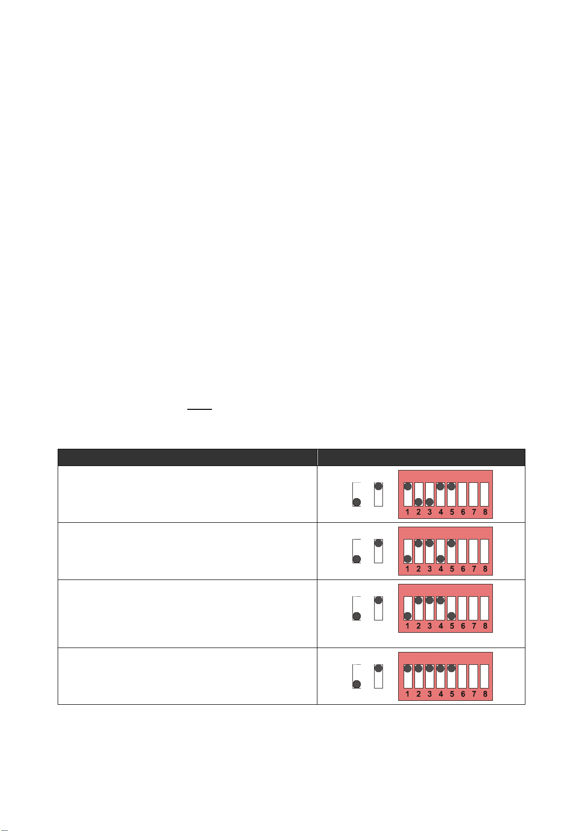
More combinations can be set with consideration of the individual function of each switch
position, according to the following table:
1 OFF: HTL level (all of the 4 input lines) ON: TTL level (all of the 4 input lines)
2 OFF: Input B is symmetric (needs /B) ON: Input B is asymmetric (single-ended, no /B)
3 OFF: Input A is symmetric (needs /A) ON: Input A is asymmetric (single-ended, no /A)
4--- ON: internal pull-up resistor towards + *)
5--- ON: internal pull-down resistor towards GND *)
*) Positions 4 and 5 both ON = Tristate, input impedance = 10 kOhms
At any time one of the positions 4 and 5 must be "ON".
With 4 and 5 both OFF, the unit may produce undefined operations
Unused inputs should always be set to HTL level
With use of Namur (2-wire) sensors, please connect the positive wire to the
corresponding input, and the negative wire to GND.
With setting HTL and NPN all impulse inputs are tied to the positive potential
of the power supply (+24 V) via internal pull-up resistors. To avoid damage
with use of TTL encoders, it is advisable to first set the unit to TTL level prior
to connection of the encoder to the unit.
3.2. Basic Switching Functions
Positions 6, 7 and 8 of switch DIL1 allow selecting the following functions:
DIL 1 DIL 1
6 OFF: Standstill detection without post-trigger
function (see clarification below)
ON: Standstill detection with post-trigger function
(see clarification below)
7 OFF: Relay 2 and Out 2 to signal the opposite
direction of the Rel1/Out1 indication
ON: Relay 2 and Out 2 to signal zero motion
(standstill)
8 OFF: Upon detection of standstill, the
direction signal is cleared (no indication)
ON: Upon detection of standstill, the information of
the last actual direction remains active
The subsequent drawing explains the difference between "post trigger function on" and
"post trigger function off". In order to get a standstill signal at all, the time distance between
two positive edges must become greater than the setting "T".
Case (1) shows the post-trigger on.
The standstill signal immediately switches off again when another active edge is detected (no
matter after which time). In this case, during slow-down of the machine, the output and the
relay might therefore produce multiple on-off cycles before the standstill signal becomes
stationary. However this method could be considered as "more safe", because it would detect
any motion, no matter how slow it is.
Case (2) shows the post-trigger off.
After the standstill signal has switched on, it will remain on and only switch off again after two
subsequent edges have been detected where the time distance was less than T.
3046 Home Road. Powell, OH 43065 P: (740) 917-5781 F: (740) 917-5791 www.GenesisAutomationOnline.com Sales@GenesisAutomationOnline.com
3046 Home Road. Powell, OH 43065 P: (740) 917-5781 F: (740) 917-5791 www.GenesisAutomationOnline.com
[email protected]