genesis LAN Splitter - Technical Manual
Page 10 Version 4 – November 2006
Correct connection
At a glance
• Three wiring examples
• GEN129 4-Way splitter
• Up to 127 LAN devices
To other LAN devices
Incorrect connections
GEN-129 GEN-129
GEN-001
X
RAS
GEN-129
GEN-129
To other LAN devices
TDC
GEN-045
GEN-129
GEN-129
RAS
GEN-030
STAR Wiring Examples:
To other LAN devices
LAN Terminations?
Please note that there are
several examples of LAN
terminations that need to be
followed as is indicated on
page 11 diagrams.
TDC
GEN-045
genesis LAN Splitter - Technical Manual
Page 3 Version 4 – November 2006
Parts Checklist:
1 x LAN Splitter (GEN-129) □
1 x 2 pin terminal blocks □
6 x 3 pin terminal blocks □
1 x 2 pin jumpers □
4 x mounting screws □
Technical Manual (this manual) □
genesis LAN Splitter - Technical Manual
Page 4 Version 4 – November 2006
Caution:All Genesis devices are electrostatic sensitive devices. As such, all care
should be taken to ensure appropriate procedures are in place when han-
dling and installing Genesis devices. This may include, but is not limited
to wearing an appropriately earthed, conductive wrist strap – to limit
electrostatic discharge into Genesis devices.
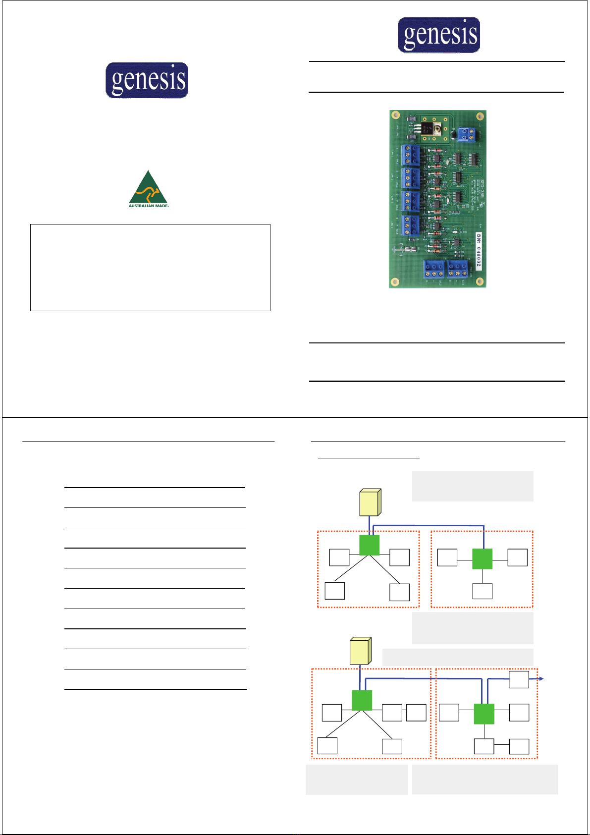
Specifications:
Dimensions (H x W x D): 145 x 75x 30 mm
Input Voltage: 11-16V DC
Standby Current Draw: 30-50mA
LAN Inputs/Outputs
LAN Sped 19.2k
LAN RS485 Inputs 1
LAN Outputs: On board 4 x LAN terminations
Distance from MU 1500m
Environmental -15 to + 50 C, 10 to 90% RH non-condensing
It is recommended to use a separate power supply, located near the LAN
splitter. DO NOT common the 0v DC, or +12v DC, of power supplies and
Genesis devices.
Points to Note:
genesis LAN Splitter - Technical Manual
Page 9 Version 4 – November 2006
Genesis LAN (cont):
LAN Termination:
The Master Unit must always be the first device on the
LAN. This device is factory fitted with a 180ΩLAN Termi-
nation Resistor.
LAN Shield:
The shield from the LAN cable should run the length of the
LAN, and should be connected to a communications earth,
at the Master Unit only. The shield terminals on each de-
vice are for connection of shield cables, and do not con-
nect to the device proper in any way
Ensure the cable shield is not connected to any ground or
to any voltage on any device and that the cable shield is
only connected to a communications earth at the Master .
Total of LAN Devices:
Up to 127 additional Genesis devices in total can be con-
nected to the Genesis LAN, across a total LAN length of
up to 1500 meters.
Last LAN Device:
The last device on the Genesis LAN must be fitted with its
termination link. This link fits a 180Ω
resistor to the last device on the LAN.
LAN impedance:
No other devices should have a termination link fitted. If
connected as described above, the LAN should have an
impedance of approximately 15Ω, per 1000 ft, plus the
resistance of the LAN cable when utilising Belden 8723
cable. This may depend on the individual installation. The
same applies for GEN129 LAN splitter on each one of the
four
terminations.
*Don’t test LAN impedance with any devices powered up.
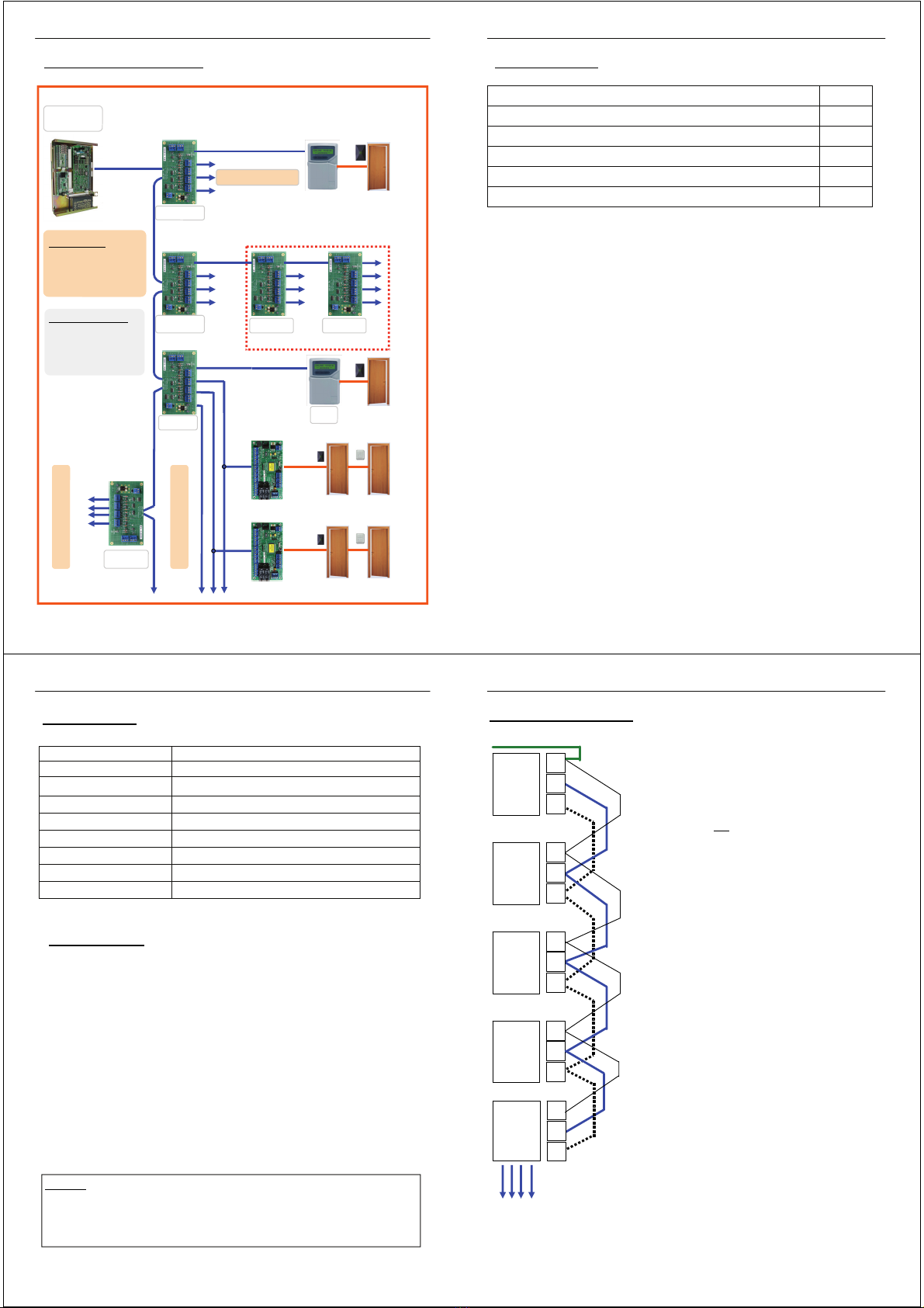
The GEN129 provides 4-way
LAN split terminations
LAN Splitter GEN129:
It is possible to cable your LAN in a 4-way STAR
wiring configuration utilising the GEN129 device.
GEN129 LAN Termination LINKS
When the GEN129 is used termination LINK must be on
the last LAN device of each LAN termination. If the
GEN129 is the last device on the LAN from the MU it also
must have the termination LINK as the last device that is
located on the module. Each one of the 4 x LAN
terminations must be terminated on the last LAN device.
Master Unit
GEN 001
Remote
Access
Stat ion
GEN 030
Expander
Unit
GEN 010
Two Door
Controller
GEN 045
A
Connect to Communications Earth
B
A
SHD
B
A
SHD
B
A
SHD
B
SHD
LAN
Splitter
GEN 129
A
B
SHD