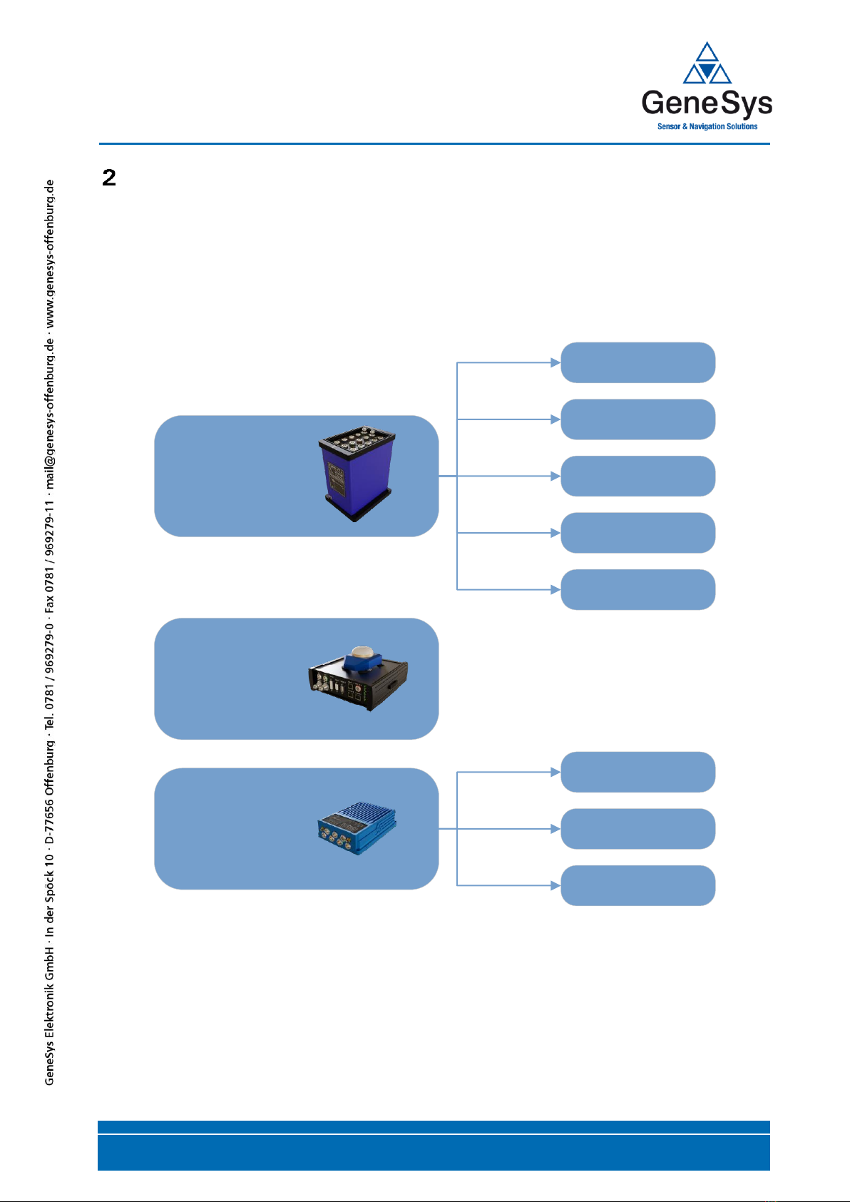
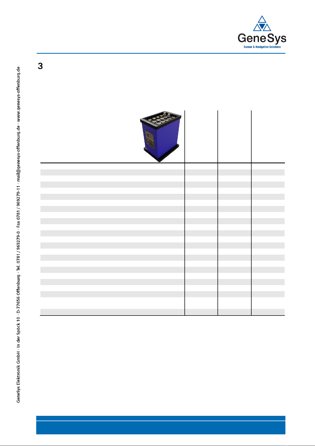
Genesys ADMA-G User manual

User Manual
ADMA-G
ADMA-Speed
ADMA-Slim
Hardware V3.0
Firmware-Version 30.9.X.X
GeneSys Elektronik GmbH
Offenburg

ADMA 3.0
USER MANUAL
Page 2/137 Document Revision 2.01 | 2021
Note
GENESYS ELEKTRONIK strives to maximize the accuracy of all its data and specifications but cannot
rule out the possibility of errors and reserves the right to future modifications without any prior notice.
GENESYS ELEKTRONIK is not obliged to maintain secrecy over any received material or other
information in the absence of any corresponding agreements made with GENESYS ELEKTRONIK prior
to submission of such information.
GENESYS ELEKTRONIK will gladly respond to enquiries and provide product details.
Copyright
Copyright @ 2021 GENESYS ELEKTRONIK GmbH. All rights reserved.
This entire user manual, or excerpts thereof, must not be reproduced, stored or transmitted in any
manner –electronically, mechanically or otherwise –without the prior approval of GENESYS
ELEKTRONIK GmbH.
Windows is a registered trademark of Microsoft Corporation
Revision
Document Revision 2.01
03/2021
Contact
GeneSys Elektronik GmbH
In der Spoeck 10
D-77656 Offenburg
Germany
Tel.: 0049 (0)781 / 96 92 79-66
Fax.: 0049 (0)781 / 96 92 79-11
Email: support@genesys-offenburg.de
Internet: www.genesys-adma.de

ADMA 3.0
USER MANUAL
Document Revision 2.01 | 2021 Page 3/137
TABLE OF CONTENTS
INTRODUCTION 6
ADMA PRODUCT FAMILY 7
2.1 ADMA-G 8
2.2 ADMA-SPEED 8
2.3 ADMA-SLIM 8
2.4 ORDERING OPTIONS 8
SCOPE OF DELIVERY 9
3.1 ADMA-G COMPONENTS 9
3.2 ADMA-SPEED COMPONENTS 10
3.3 ADMA-SLIM COMPONENTS 11
FRONT VIEW AND INTERFACES 12
4.1 ADMA-G 12
4.2 ADMA-SPEED 14
4.3 ADMA-SLIM 16
ADMA WEBINTERFACE 18
5.1 TPC/IP SETTINGS 19
5.2 CONNECT TO THE ADMA WEBINTERFACE 21
5.3 ADMA-SYSTEM AND GNSS-RECEIVER INFORMATION 21
ADMA LABORATORY BENCH TEST 22
7.1 SETUP AND CABLING 22
7.2 ADMA CONFIGURATION FOR BENCH TESTING 23
7.3 SETUP THE DATA ACQUISITION (DAQ) 29
7.4 STATIC TEST 30
7.5 DYNAMIC TEST 33
INSTALLATION AND CABLING INSIDE THE VEHICLE 35
8.1 POINT OF INSTALLATION 35
8.2 CABLING 41
8.3 MODIFY THRESHOLD FOR AUTOINIT, HEADING CTRL. AND DUAL ANTENNA USE 43
8.4 STANDSTILL DETECTION 44
8.5 MODIFY THRESHOLDS FOR QUALITY INDICATION 47
8.6 RELATIVE COORDINATE SYSTEM 49
8.7 COMPENSATING AN ADMA MISALIGNMENT 51
8.8 COMPENSATING THE INSTALLATION POSITION 52

ADMA 3.0
USER MANUAL
Page 4/137 Document Revision 2.01 | 2021
OPERATIONAL CONFIGURATIONS 59
9.1 OVERVIEW OF POSSIBLE CONFIGURATIONS WITH ADMA 59
9.2 TEST MANOEUVRES AND OPERATING CONFIGURATIONS 60
9.3 RECEIVER SETTINGS 61
9.4 DGNSS OPTIONS 62
9.5 STEERING AND DRIVING ROBOT DATA OUTPUT 68
9.6 SIGNAL OUT 70
9.7 SIGNAL IN 71
9.8 EXTERNAL VELOCITY 72
9.9 RAW DATA RECORDING FOR POST-PROCESSING 75
MEASUREMENT DATA 76
10.1 UTILISED COORDINATE SYSTEMS 76
10.2 GENERALITIES TO THE UTILISED COORDINATE SYSTEMS 76
10.3 ORIENTATION MEASUREMENT 81
10.4 POI-TRANSFORMED ADMA DATA 82
10.5 POSITION INFORMATION 83
10.6 RELATIVE, METRIC COORDINATE SYSTEM 85
MEASURING MODE 86
11.1 START SEQUENCE 86
11.2 SYSTEM SETTINGS 88
11.3 START MEASUREMENT 88
11.4 PRE-ALIGNMENT 89
11.5 AUTOINIT 89
11.6 TRANSIENT PHASE OF THE KALMAN FILTER 90
ADD-ON AND ADD-IN 93
12.1 ADD-ON - DELTA DATA 93
12.2 ADD-ON - BRAKING DATA 101
12.3 ADD-ON –FILTER 111
12.4 ADD-IN - CORRECTION DATA FORWARDING 113
12.5 ADD-IN - CORRECTION DATA VIA ETHERNET 116
12.6 ADD-IN - GNSS RAW DATA VIA ETHERNET 119
LICENSE MANAGEMENT 121
FIRMWARE UPDATES 122
15.1 ADMA - FIRMWARE UPDATE 122
15.2 GNSS-RECEIVER - FIRMWARE UPDATE 123

ADMA 3.0
USER MANUAL
Page 6/137 Document Revision 2.01 | 2021
Introduction
This user manual serves as an aid in commissioning the ADMA (Automotive Dynamic Motion Analyzer)
gyro system.
The first part of the manual describes a routine for testing whether the ADMA gyro system's inertial
sensors are operating without error. This function test is also a good way to become familiar with
ADMA and to gain experience in setting up the ADMA.
The second part of the manual describes a typical configuration of a test vehicle, including auxiliary
sensors such as an external speed measurement system or a GNSS.
The ADMA (Automotive Dynamic Motion Analyzer) is a strapdown inertial measurement system
equipped with robust gyros and accelerometers and adapted specially for automotive measurements.
To maintain system performance even during complicated test manoeuvres, a DGNSS has been
integrated.
The ADMA uses an extended Kalman filter for data fusion of INS data and (D)GNSS data / external
velocity data. The ADMA provides not only raw data of the 6 inertial sensors, but a variety of motion
states, other additional states and system status. Measurement data supplied by the ADMA include:
•ADMA status
•Rates
•Accelerations
•Tilt, yaw und side slip angle
•Velocity (GNSS, Inertial, external source)
•Position absolute (GNSS and Inertial)
•Position relative (GNSS and Inertial)
•Standard deviation of tilt, yaw, velocity and position
•Sample time, system temperature
•GNSS time and ADMA time (based on GNSS time)
•Time reference of event inputs
With the data available, a multitude of applications can be covered, such as:
•Vehicle dynamics
•Measurements of vehicle body motion
•Analysis of driving comfort
•Measurements of carriageways and routes
•Validation of simulation models
•Reference for developing driving assistance systems (e.g. ABS, ASR, ESP; AEB, LSS,..)
•Brake test
•Precise speed measurement
•Acceleration and deceleration testing
•Road holding tests
•Tire testing
•ADAS (Advanced Driver Assistance Systems) evaluation

ADMA 3.0
USER MANUAL
Document Revision 2.01 | 2021 Page 7/137
ADMA product family
•There are three divisions within the ADMA family, which contain several different models.
The divisions vary in housing and at the hardware specification. Not all functions described in
this Manual are available with ADMA-Speed or ADMA-Slim. Each distinction between ADMA-
G, ADMA-Speed and ADMA-Slim is explained in this Manual.
•Some functions require a license. Therefore, refer to the technical specifications of your
device.
ADMA-G
ADMA-Speed
ADMA-Slim
ADMA-G-Pro+
ADMA-G-ECO
ADMA-G-ECO+
ADMA-G-EntryLevel
ADMA-G-EntryLevel+
Standard Version
Single Connector
Version
OEM Version
Figure 1 ADMA product family

ADMA 3.0
USER MANUAL
Page 8/137 Document Revision 2.01 | 2021
2.1 ADMA-G
The ADMA-G models differ in performance of the applied inertial sensors. Higher precision sensors
are less sensitive to GNSS interference or outages. Our gyro system does not require an export license.
All models are available with variable GNSS accuracy, ranging from simple L1 receivers with meter
accuracy to L1/L2 RTK receivers with centimeter accuracy. Likewise, all models are available as single
and dual antenna version with optional GNSS systems like GLONASS, Beidou, Galileo etc.
The configuration of all ADMA systems can be done quickly and easily via web browser.
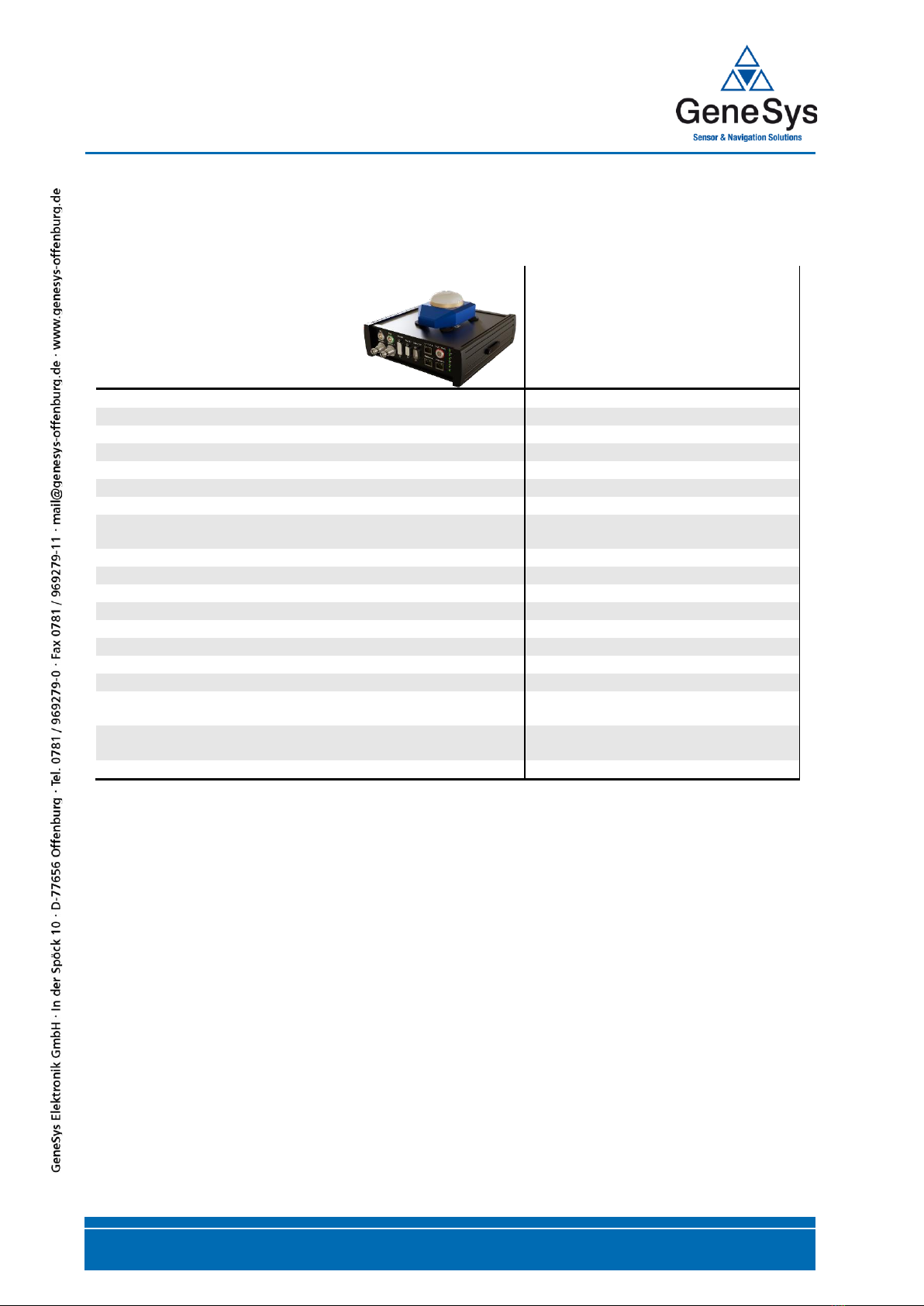
2.2 ADMA-Speed
The ADMA-Speed is a GNSS speed sensor with integrated inertial sensors. It is optimized for brake
tests. For easy installation, the inertial sensors are integrated in the GNSS antenna. All motion data
of the vehicle is calculated by means of the tried and tested ADMA technology. In the BASIC version
acceleration, speed and braking distance is transmitted via the CAN and Ethernet interface. ADMA-
Speed eliminates the known disadvantages of GNSS speed sensors.
Optionally, ADMA-speed can be expanded to a full-fledged GNSS-aided inertial system with
centimeter position accuracy, eg. for vehicle dynamics testing or verification of driver assistance
systems.
2.3 ADMA-Slim
The ADMA-SIim is a full-fledged GNSS/InertiaI System based on MEMS gyroscopes and
accelerometers and a high performance geodetic GNSS receiver. Comparing the performance it is
similar to our ADMA-G-EntryLevel or ADMA-Speed models. The ADMA-SIim has been designed for
applications with space or weight restrictions, e.g. to be integrated in walk-on-able platforms for GSTs
(Guided Soft Targets) or VRU (Vulnerable Road User) dummies.
ADMA-Slim is available in three different versions:
•standard version whit Lemo connectors
•single connector version whit MIL connector
•unhoused OEM version
2.4 Ordering options
All models of the ADMA family can be ordered as single or dual GNSS antenna version.
2.4.1 Single GNSS antenna version
For the most vehicle testing applications, a single antenna version is sufficient.
The combination of INS and GNSS allows precise output of the yaw angle at low speed and stationery
maneuvers, thanks intelligent algorithmic and a standstill detection.
2.4.2 Dual GNSS antenna version
The dual GNSS antenna version allows the output of a precise yaw angle even without prior
initialization of the ADMA. This feature is important for very slow vehicles or at low friction tests,
such as on ice.

ADMA 3.0
USER MANUAL
Document Revision 2.01 | 2021 Page 9/137
Scope of delivery
3.1 ADMA-G components
ADMA products are completely supplied including basic cables, GNSS antenna, software and manual.
Other components are available, please contact us for more information.
Description
ADMA-G Pro+
ADMA-G ECO+
&
ADMA-G ECO
ADMA-G EntryLevel+
&
ADMA-G EntryLevel
ADMA-G module
■
■
■
ADMA power cable
■
■
■
ADMA COM cable
■
■
■
ADMA CAN1 cable
■
■
■
ADMA CAN2-5 cable
□
□
□
ADMA GNSS antenna cable
■
■
■
ADMA Ethernet cable
■
■
■
ADMA AUX cable for
■
■
■
GNSS antenna
■
■
■
Magnetic base for GNSS antenna
■
■
■
Radio modem
□
□
□
Radio antenna with magnetic base and antenna cable
□
□
□
GPRS modem
□
□
□
GPRS antenna with magnetic base and antenna cable
□
□
□
ADMA Modem connection cable
□
□
□
ADMA Signal-In cable
□
□
□
ADMA Signal-Out cable
□
□
□
ADMA Sync-Out cable
□
□
□
ADMA Aux-Out cable
□
□
□
ADMA External Velocity cable
□
□
□
WiFi-Kit
□
□
□
Software package for configuration and data recording
■
■
■
Technical Documentation, ADMA user manual, Quick Guide
Version
■
■
■
Rugged aluminum transport case
■
■
■
■included in scope of delivery
□optional

ADMA 3.0
USER MANUAL
Page 10/137 Document Revision 2.01 | 2021
3.2 ADMA-Speed components
ADMA-Speed product is completely supplied including basic cables, GNSS antenna, software and
manual. Other components are available, please contact us for more information.
Description
ADMA-Speed
ADMA-Speed control unit
■
ADMA-Speed sensor unit
■
ADMA-Speed power cable
■
ADMA-Speed COM cable
□
ADMA-Speed CAN1 cable
■
ADMA-Speed Ethernet cable
■
ADMA-Speed config cable for internal GNSS
■
ADMA-Speed GNSS antenna cable and ADMA-Speed IMU
cable
■
Radio modem
□
Radio antenna with magnetic base and antenna cable
□
GPRS modem
□
GPRS antenna with magnetic base and antenna cable
□
ADMA-Speed Modem connection cable
□
ADMA-Speed Signal-In cable
□
ADMA-Speed Signal-Out cable
□
WiFi-Kit
□
Technical Documentation, ADMA user manual, Quick Guide
Version
■
Software package for data monitoring and recording, running
on Tablet and PC with Windows OS
■
Hard top transport case
■
■included in scope of delivery
□optional

ADMA 3.0
USER MANUAL
Document Revision 2.01 | 2021 Page 11/137
3.3 ADMA-Slim components
ADMA-Slim LEMO, MIL and OEM product is completely supplied including basic cables, GNSS
antenna, software and manual. Other components are available, please contact us for more
information.
Description
ADMA-Slim
LEMO-connector
ADMA-Slim
MIL-connector
ADMA-Slim
OEM
ADMA-Slim module
■
■
□
ADMA power cable
■
□
□
ADMA CAN cable
■
□
□
ADMA Ethernet cable
■
□
□
ADMA config cable for internal GNSS receiver
■
□
□
GNSS patch antenna
■
■
□
ADMA GNSS antenna cable 20cm
■
■
□
ADMA GNSS antenna cable 5m
■
■
□
ADMA MIL cable open end
□
■
□
Radio modem
□
□
□
Radio antenna with magnetic base and antenna cable
□
□
□
GPRS modem
□
□
□
GPRS antenna with magnetic base and antenna cable
□
□
□
ADMA Modem connection cable
□
□
□
ADMA Signal-In cable
□
□
□
ADMA Signal-Out cable
□
□
□
WiFi-Kit
□
□
□
Technical Documentation, ADMA user manual, Quick
Guide Version
■
■
■
Software package for data monitoring and recording,
running on Tablet and PC with Windows OS
■
■
■
Hard top transport case
■
■
□
■included in scope of delivery
□optional

ADMA 3.0
USER MANUAL
Page 12/137 Document Revision 2.01 | 2021
Front view and interfaces
4.1 ADMA-G
Figure 2 ADMA-G front view
Interface
Description
Ethernet 1
Interface for ADMA data output, configuration and firmware update, steering
and driving robot data output, optional for relative data calculation (e.g. range)
and DGNSS routing, input/output.
Ethernet 2
Interface for driving robot data output, optional for relative data calculation
(e.g. range) and DGNSS routing, input/output.
Ethernet 3
Interface for driving robot data output, optional for relative data calculation
(e.g. range) and DGNSS routing, input/output.
COM
RS232 configuration via ADMA System Software (only legacy settings) and
data interface.
CAN 1
CAN 2b interface 1 for data output.
CAN 2-5
CAN 2b interface 2 to 5 for data output (License required).
Signal Out
Digital output:
•Sync out to assist synchronization.
•Frequency out to assist synchronization.
•Status information.
•GNSS PPS.
•Pulses distance travelled.
Signal In
Digital input:
•Time measurement input for offline synchronization.
•Trigger input e.g. for light barrier or brake trigger.
Analog input:
•Analog signal measurement
Baro
GeneSys Barometer interface. (No longer supported)

ADMA 3.0
USER MANUAL
Document Revision 2.01 | 2021 Page 13/137
Modem
RS232 data interface for:
•Correction data input
•GNSS Receiver firmware
updates
•GNSS RAW data logging
•GPRMC data logging
Aux System
RS232 data interface for:
•GNSS Receiver firmware
updates
•GNSS RAW data logging
•GPRMC data logging
Ext Vel
Analog interface for external speed measurement systems.
GNSS Ant 1
Primary GNSS Antenna
GNSS Ant 2
Secondary GNSS Antenna (for Dual Antenna Systems)
9-32V DC In
12 VDC nominal supply voltage (input voltage range 9 - 32 VDC)
Load dump protection
4.1.1 Status operating mode ADMA-G
Port
LED
Description
9-32 V DC IN
⚫
⚫
OFF
OFF
No supply voltage
9-32 V DC IN
⚫
⚫
ON
OFF
Supply voltage connected
ADMA boot process started
9-32 V DC IN
⚫
⚫
ON
ON
Ready for operation
Modem
⚫
ON
Modem port activated
Baro
⚫
ON
Baro activated (No longer supported)
CAN1-5
⚫
Data output via CAN
Ethernet1-3
⚫
⚫
Data
Link
COM
⚫
⚫
Data output via COM

ADMA 3.0
USER MANUAL
Page 14/137 Document Revision 2.01 | 2021
4.2 ADMA-Speed
Figure 3 ADMA-Speed front view
Interface
Description
Ethernet 1
Interface for ADMA data output, configuration and firmware update, steering
and driving robot data output, optional for relative data calculation (e.g. range)
and DGNSS routing, input/output.
Ethernet 2
Interface for driving robot data output, optional for relative data calculation
(e.g. range) and DGNSS routing, input/output.
Ethernet 3
Interface for driving robot data output, optional for relative data calculation
(e.g. range) and DGNSS routing, input/output.
COM
RS232 configuration via ADMA System Software (only legacy settings) and
data interface.
CAN 1
CAN 2b interface for data output.
Signal Out
Digital output:
•Sync out to assist synchronization
•Frequency out to assist synchronization
•Status information
•GNSS PPS
•Pulses distance travelled
Signal In
Digital input:
•Time measurement input for offline synchronization
•Trigger input e.g. for light barrier or brake trigger.
Analog input:
•Analog signal measurement
Modem
RS232 data interface for:
•Correction data input
•GNSS Receiver firmware
updates
•GNSS RAW data logging
•GPRMC data logging
GNSS Ant 1
Primary GNSS Antenna
GNSS Ant 2
Secondary GNSS Antenna (for Dual Antenna Systems)
9-32V DC In
12 VDC nominal supply voltage (input voltage range 9 - 32 VDC)
Load dump protection

ADMA 3.0
USER MANUAL
Document Revision 2.01 | 2021 Page 15/137
4.2.1 Status operating mode ADMA-Speed
Port
LED
Description
9-32 V DC IN
⚫
⚫
OFF
OFF
No supply voltage
9-32 V DC IN
⚫
⚫
ON
OFF
Supply voltage connected
ADMA boot process started
9-32 V DC IN
⚫
⚫
ON
ON
Ready for operation
State
⚫
ON
Ready for operation
Modem
⚫
ON
Modem port activated
CAN1
⚫
Data output via CAN
Ethernet1-3
⚫
⚫
Data
Link
IMU
⚫
ON
IMU connected
Signal
⚫
ON
+ 5V DC and +12V DC power at signal out port active

ADMA 3.0
USER MANUAL
Page 16/137 Document Revision 2.01 | 2021
4.3 ADMA-Slim
Figure 4 ADMA-Slim Lemo version and ADMA-Slim MIL version front view
Interface
Description
Ethernet
For data output, configuration and firmware update, steering and driving robot
data output, optional for relative data calculation (e.g. range) and DGNSS
routing, input/output.
COM
RS232 configuration via ADMA System Software (only legacy settings) and
data interface.
CAN
CAN 2b, 1Mbit for data output.
Signal Out
Digital output:
•Sync out to assist synchronization
•Frequency out to assist synchronization
•Status information
•GNSS PPS
•Pulses for distance travelled
Signal In
Digital input:
•Time measurement input for offline synchronization
•Trigger input e.g. for light barrier or brake trigger
Analog input:
•Analog signal measurement
Modem
RS232 data interface for:
•Correction data input
•GNSS receiver firmware
updates
•GNSS RAW data logging
•GPRMC data logging
GNSS Ant 1
Primary GNSS Antenna
GNSS Ant 2
Secondary GNSS Antenna (for Dual Antenna Systems)
9-32V DC In
12 VDC nominal supply voltage (input voltage range 9 - 32 VDC)

ADMA 3.0
USER MANUAL
Document Revision 2.01 | 2021 Page 17/137
4.3.1 Status operating mode ADMA-Slim
Port
LED
Description
Power
9-32 V DC IN
⚫
⚫
OFF
ON
No supply voltage
Supply voltage connected
Core Status
⚫
⚫
⚫
OFF
ON
ON
No supply voltage
Ready for operation
booting
COM
⚫
Data output via COM
CAN1
⚫
Data output via CAN
ETH Data
⚫
⚫
OFF
No data output via ETH
Data output via ETH
ETH Link
⚫
⚫
OFF
ON
No Link (Network disconnected)
Link
GNSS Status
⚫
⚫
ON
GNSS OK
GNSS Error

ADMA 3.0
USER MANUAL
Page 18/137 Document Revision 2.01 | 2021
ADMA Webinterface
The ADMA provides options for certain user-specific and operational settings / configurations. On
application of the supply voltage, the system runs through an initialization phase which ends in
standby mode. Then the available settings and configuration parameters of the ADMA can be modified
via Webinterface http://192.168.88.30.
These settings include:
•Interface parameters for data transmission (CAN / COM / Ethernet)
•Transmission rate for the CAN interface
•CAN identifier type (standard / extended) and initial ID in the address space
•Sampling rate (50 up to 400 Hz) or (50 up to 1000 Hz) depending on ADMA system type
•Data to be transmitted
•Coordinate system
•Pre-alignment setting
•Enabling of DIO signals such as system clock and error-out
•GNSS details
•Details on external speed signals
•Values for compensating misalignments of the ADMA
•Values for compensating of mounting positions of the ADMA and GNSS antenna
•Lever arm values for point of interest calculations
The configuration of the ADMA can be saved to and loaded from file, thus permitting a storage and
reuse of various measurement configurations in separate files.
Recommended web browsers:
The list below will give an overview of browsers we support. JavaScript is required.
Windows
Mac
Microsoft Internet Explorer
Microsoft Edge
Mozilla Firefox
Google Chrome
(latest versions)
Apple Safari
Mozilla Firefox
(latest versions)

ADMA 3.0
USER MANUAL
Document Revision 2.01 | 2021 Page 19/137
5.1 TPC/IP settings
The Webinterface is integrated in the ADMA. For access, the following settings of the network
connection must be done:
1Open Network Connections by clicking the Start button . Then click Control Panel. Open
Network and Sharing Center click View network connections.
2Right-click the connection that you want to change, then click Properties . If you're asked
for an administrator password or confirmation, enter the password or provide the required
confirmation.
3Click the Networking tab. Under This connection uses the following items, choose Internet
Protocol Version 4 (TCP/IPv4), then choose Properties.
Figure 5 The Network Connection Properties dialog box

ADMA 3.0
USER MANUAL
Page 20/137 Document Revision 2.01 | 2021
4To specify an IP address, click Use the following IP address, and then, in the IP address,
Subnet mask, and type in the following IP address settings:
IP –Adress: 192.168.88.XXX
Subnet mask: 255.255.255.0
Figure 6 The Internet Protocol Version 4 (TCP/IPv4) Properties dialog box
5To check your settings, please start the internet browser of your computer. Type in
http://192.168.88.30 in the address bar of your browser, the ADMA Webinterface should
appear.
NOTE: Your Proxy settings must be deactivated!
This manual suits for next models
5
Table of contents
Popular Automobile Accessories manuals by other brands

Thule
Thule Rapid System Kit 1659 instructions

ACV
ACV 381143-55-1 installation manual

Lamko Group
Lamko Group LK-168C Installation and operational instructions

Steinhof
Steinhof F-295 FITTING AND OPERATION MANUAL

Conrad
Conrad CE4 operating instructions

Safe Fleet
Safe Fleet Rear View Safety RVS-778718N instruction manual