GenixGreen POWERWALL ES-BOX2 User manual

POWERWALL
LiFePO4 Lithium Iron Phosphate Battery

ES-BOX2
LiFePO4(LFP)
Intermal Resistance
Charge/Discharge Current(A)
Model
Battery Type
Norminal Voltage(V)
Norminal Energy(KWH)
Cycle Life
Smart
Each module is equipped with
an independent BMS system.
Safe
Safe lithium iron
phosphate battery cell.
Modular
Modular expansion.
Longer Lifetime
6000 cycles,15 years
design life.
Easy Installation
Just Plug & Play.
Certifications
CE IEC
UN38.3 MSDS.
A dvancingPo w er
100AH
5.12KWH
51.2V
≤2W
350*100*45mm
Rated Voltage 51.2V
Balance Current 30-65(MA)
Communication Method CAN/RS485/RS232
Information Storage 500 Strip
Limiting 10/20A(Optional)
Operating Temperature -10℃-50℃
Storage Temperature 10℃-50℃
Humidity 15%-75%
Warranty
Warranty 5 Years
Product Description
51.2V100AH
Technical Specifications
Design Capacity
Design Years 15 Years
Product Size
600*510*173mm
51kg
Size
Size
Weight
Technical Parameter
Operating Voltage Range
Charging Voltage
Rated Capacity
≥6000 80% DOD
40V-58.4V
DC 58.4V
100AH
Same Port 100A
≤30m Ω
BMS Parameters
Self-Consumption
Ambient Temperature
Lithium battery systems are widely used in residential energy storage systems, such as solar energy
storage systems and UPS. The power wall LiFePO4 battery pack adopts the international advanced
lithium iron phosphate battery application technology and BMS control technology.
2022 Shenzhen Genixgreen Technology Co., Ltd All Rights Reserved.

173.00
509.62
599.67
R4.25
R4.00
Product Size:
Product interface:
①Switch ②RS485 ③RS485 ④RS232 ⑤CAN/RS485(External Communication)
⑥Dry contact ⑦ADD ⑧RST ⑨Power + ⑩Power -
2022 Shenzhen Genixgreen Technology Co., Ltd All Rights Reserved.
①
②③④⑤⑥⑦⑧
⑨ ⑩
Genixgreen
BOX2-5.12KWH
Genixgreen
BOX2-5.12KWH
ON/OFF
RUN ALM
SOC

Parallel connection of batteries
Connect the positive pole and positive pole in parallel, and the negative
pole and negative pole in parallel, as shown in the figure below
Solution diagram
Accessories:(Optional)
Fixed pendant*1
Fixed mounting ears*2
Fixing bolt*10
PV
Cloud Platform
Battery lmportant Load Normal Load
Meter or CT
GRID
DC Line
AC Line
2022 Shenzhen Genixgreen Technology Co., Ltd All Rights Reserved.
1000MM*1
1000MM*1

Installation Notes:
1. As shown in the figure below, press the fixed pendant on the wall
surface with one hand, use a marker to draw the installation positioning
hole of the fixed pendant, and use a tool to drill.
Wall position punching*3PCS Wall position punching*3PCS
2. As shown in the figure below, fix the attached six M8 expansion bolts
in the opening of the pendant, and tighten the nuts on the bolts.
3. Lift up the 51.2V100AH battery box, adjust the opening of the pendant
on the back of the box to align with the pendant on the wall as shown
in the figure below, and then use a marker to mark the mounting ears
of the box, and use tools to drill holes for the mounting ears.
Box pendant opening position
Fixed pendant
After completion as shown in the figure
2022 Shenzhen Genixgreen Technology Co., Ltd All Rights Reserved.
Genixgreen
BOX2-5.12KWH
ON/OFF
RUN ALM
SOC

4. As shown in the figure below, fix the supplied 4 M8 expansion bolts in
the holes of the mounting ears and fasten the nuts on the bolts.
2022 Shenzhen Genixgreen Technology Co., Ltd All Rights Reserved.
After completion as
shown in the figure
Genixgreen
BOX2-5.12KWH
Warning
To ensure proper use of the battery please read the manual carefully before using it.
●Handling
●Do not expose to, dispose of the battery in fire.
●Do not put the battery in a charger or equipment with wrong terminals connected.
●Avoid shorting the battery
●Avoid excessive physical shock or vibration.
●Do not disassemble or deform the battery.
●Do not immerse in water.
●Do not use the battery mixed with other different make, type, or model batteries.
●Keep out of the reach of children.
●charge and discharge
●Battery must be charged in appropriate charger only.
●Never use a modified or damaged charger.
●Do not leave battery in charger over 24 hours.
●storage
●Store the battery in a cool, dry and well-ventilated area.
●disposal
●Regulations vary for different countries. Dispose of in accordance with local regulations.
ON/OFF
RUN ALM
SOC

2022 Shenzhen Genixgreen Technology Co., Ltd All Rights Reserved.
Flash mode Bright
Flash, 1 0.25S 3.75S
Flash, 2 0.5S 0.5S
Flash, 3 0.5S 1.5S
The state Charge Discharge
Capacity indicator light
L4 L3 L2 L1 L4 L3 L2 L1
Quantity of electricity (%)
0~25%
25 ~50 %
50 ~75 %
75 ~10 0 %
off off off
offoff
off off
off
off
off
off
off
off
Lighting Lighting Lighting Lighting Lighting Lighting Lighting
Lighting
Lighting
Lighting
LightingLighting
LightingLighting LightingLighting
Flash
2
Flash
2
Flash
2
Flash
2
State Normal / alarm /
protection
RUN ALM The power level indicates the LED Explain
Shut down Dormancy All off
Await the
opportune
moment
Normal According to the electricity
instruction
Stand by
Report an emergency Module low pressure
Charge
Normal According to the electricity
instruction (Power level indicates
maximum LED flash 2)
Report an emergency
Overcharge protection
Temperature, overcurrent,
and failure protection
protect
Stop charging
Discharge
Normal According to the electricity
instruction
Report an emergency
Undervoltage protection Stop discharge
Temperature, over-
current, short-circuit,
Reverse connection and
failure protection
Stop discharge
Lose
efficacy
Stop charging and
discharging
off off off off off off
off
off
off
off off off off off
off
off
off off off off off
off off off off off
off off off off off
Lighting
Lighting
Lighting
Lighting
Lighting
Lighting
Lighting Lighting Lighting Lighting
Alarm when
overvoltage
light off
If there is no charging,
the indicator light is in
standby state
Flash 3
Flash 3
Flash 3Flash 1
Flash 1
Flash 3 Flash 3
Table 1 LED working status indication
Table 2 Capacity indication instructions
Tabl 3 LED flash instructions
Note: can enable or prohibit LED indicator light alarm through the upper machine, the factory default is enabled.
LED instructions

2022 Shenzhen Genixgreen Technology Co., Ltd All Rights Reserved.
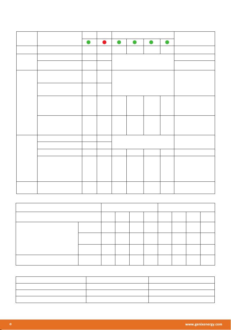
Buzzer action description
Power on, buzzer ringing;
Shutoff sleep, buzzer short;
When short circuit protection, the buzzer calls every 2S, short circuit protection 3 lock, the buzzer no longer calls; the buzzer
function can be enabled or prohibited through the upper machine, the factory is prohibited by default;
When the buzzer function is prohibited, the buzzer does not work during the protection board alarm and protection (except for
short circuit and reverse connection protection);
Key instructions
When the BMS is dormant, the key press is greater than 1S and the protection board is activated.
When the BMS is working, pressing the key pressed for more than 3S and less than 6S, the BMS goes dormant.
When the BMS is working and the key press lasts longer than 6S, the protection plate is reset.
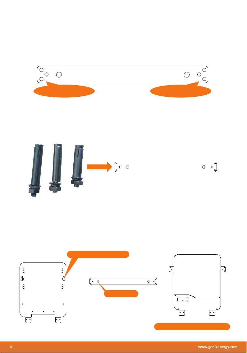
Sleep and wake up
1. Dormancy
To reduce the power consumption of the entire system, the system is dormant and enters hibernation mode when the following
conditions are met:
1) The single overrelease protection is still not lifted for 5 minutes (the time can be set).
2) The standby state duration reaches 24 hours (no communication, no charge and discharge, no charger access).
3) Open the composite button switch according to the operating rules.
4) By using the "forced hibernation" button of the upper computer computer, the protection board can be forcibly shut down
to enter the hibernation mode.
2. Wake-up function description
Combined with the actual situation, for the convenience of use, the system provides a variety of different ways of waking up:
1) Charging wake-up, access to the charger, the charger voltage is greater than 36V;
2) Keys wake up;
3) Communication wake up can be awakened through RS485-1, RS232 serial port and CAN communication; please note that the
battery is monomer or overall overput into dormant mode, not serial port;
Communication instructions
1. RS232 communication
The BMS can communicate with the upper computer computer through the RS232 interface to monitor various battery
information at the upper computer end, including battery voltage, current, temperature, status, SOC, SOH and battery production
information, with a default port rate of 9600bps.
2. RS485 communication
With a dual RS485 interface, you can view the information about the PACK, and the port rate defaults to 9,600 bps.If you
need to communicate with the monitoring equipment through RS485, the monitoring equipment as the host, poll the data
according to the address, the address setting range is 1~16.
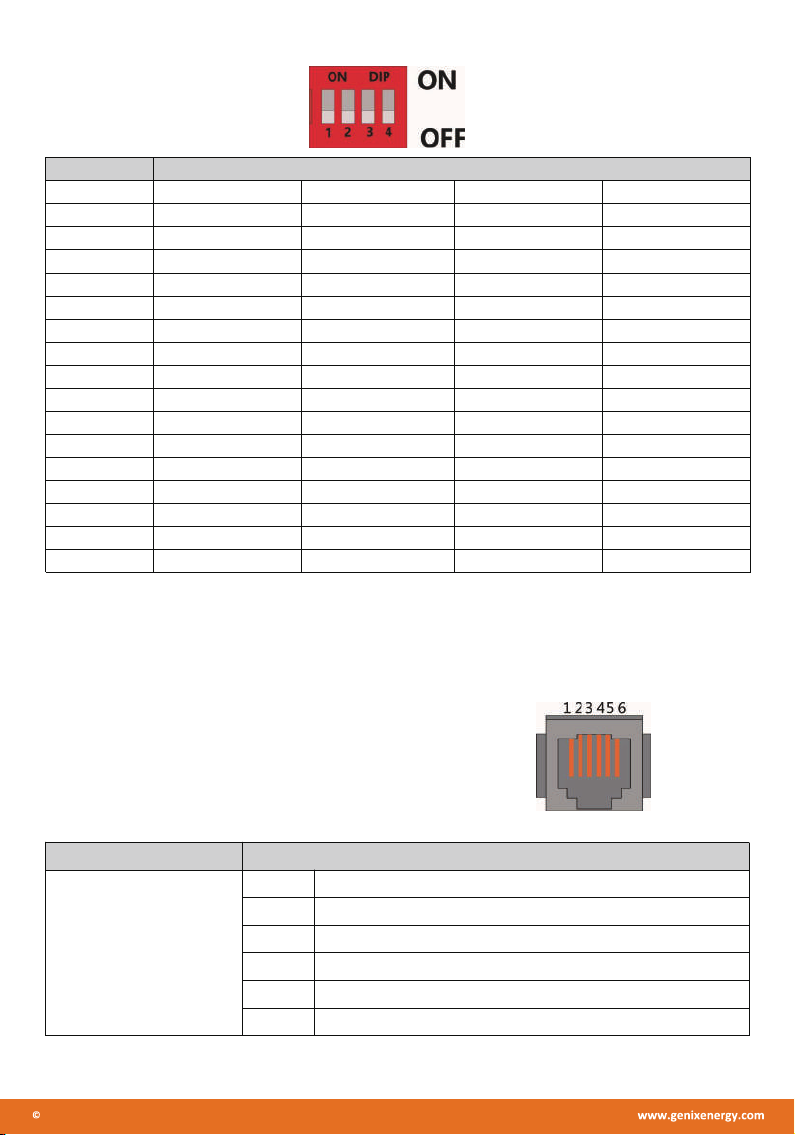
3. Dial-up switch settings
When PACK is used in parallel, different PACK can be distinguished by setting the dialing switch on BMS to avoid setting the
same address. The definition of BMS dial switch refers to the following table.

2022 Shenzhen Genixgreen Technology Co., Ltd All Rights Reserved.
#1 #2 #3 #4
1OFF OFF OFF OFF
2ON OFF OFF OFF
3OFF ON OFF OFF
4ON ON OFF OFF
5OFF OFF ON OFF
6ON OFF ON OFF
7OFF ON ON OFF
8ON ON ON OFF
9OFF OFF OFF ON
10 ON OFF OFF ON
11 OFF ON OFF ON
12 ON ON OFF ON
13 OFF OFF ON ON
14 ON OFF ON ON
15 OFF ON ON ON
16 ON ON ON ON
Table 5 Dial switch position
Interface definition
Diagram diagram of the communication interface
RS232 communication port definition:
P I N 1 N C ( e m p t y )
P I N 2 N C ( e mp t y )
P I N 3 T X p r ot e c t i o n b oa r d s e n d s d a t a ( co m p u t e r r e c ei v i n g d a t a f o ot )
P I N 4 RX p r o t e c t io n b o a r d r e c ei v e s d a t a ( c o m pu t e r s e n d s d at a )
P I N 5 G ro u n d s i g n a l g ro u n d
P I N 6 N C ( e mp t y )
Table 6 The RS 232 Port Definition
Address Codes the switch position
Interface Defined declaration
X7
Communication port
definition

2022 Shenzhen Genixgreen Technology Co., Ltd All Rights Reserved.
RS485-1 / CAN communication interface definition:
I n t er f a c e D e f in e d d e c la r a t i o n D e f i n e d d e c l a r a t i o n
P I N 1 C A N L P I N 1 R S 48 5 - B 1
P I N 2 C G N D P I N 2 R S 4 8 5 - A 1
P I N 3 N C ( e m p t y ) PI N 3 R S 4 8 5 - G N D
P I N 4 C A N H P I N 4 RS 4 8 5 - B 1
P I N 5 C A N L P I N 5 R S 48 5 - A 1
P I N 6 N C ( e m p t y ) PI N 6 R S 4 8 5 - G N D
P I N 7 C G N D P I N 7 N C ( e m p t y )
P I N 8 CA N H PI N 8 N C ( e m p t y )
Table 7 The RS 485-1 / CAN port definition
RS485-2 Communication interface Definition:
P I N 1 RS 4 8 5 - B 2 P I N 1 R S 4 8 5 -B 2
P I N 2 RS 4 8 5 - A 2 P I N 2 R S 4 8 5 -A 2
P I N 3 R S 4 8 5 -G N D P I N 3 R S 4 8 5- G N D
P I N 4 N C ( em p t y ) P I N 4 N C ( e m p t y)
P I N 5 N C ( em p t y ) P I N 5 N C ( e m p t y)
P I N 6 R S 4 8 5 -G N D P I N 6 R S 4 8 5- G N D
P I N 7 RS 4 8 5 - A 2 P I N 7 R S 4 8 5 -A 2
P I N 8 RS 4 8 5 - B 2 P I N 8 R S 4 8 5 -B 2
Table 8 The RS 485-2 port definition
Interface Defined declaration Defined declaration
X2
Communication port
definition
X1
Communication port
definition
A part
CAN joggle
B part
RS-485-1
Interface
A part
RS-485-2
Interface
B part
RS-485-2
Interface

2022 Shenzhen Genixgreen Technology Co., Ltd All Rights Reserved.
Battery Operation Instruction
●Charging
Charging current:Cannot surpass the biggest charging current which in this specification book stipulated.
Charging voltage:Does not have to surpass the highest amount which in this specification book stipulated
to decide the voltage.
Charge temperature:The battery must carry on the charge in the ambient temperature scope which this
specification book stipulated.
Uses the constant electric current and the constant voltage way charge, the prohibition reverse charges.
If the battery positive electrode and the cathode meet instead, can damage the battery.
●Discharging current
The discharging current does not have to surpass this specification book stipulation the biggest discharging
current, the oversized electric current electric discharge can cause the battery capacity play to reduce and to
cause the battery heat.
●Electric discharge temperature
The battery discharge must carry on in the ambient temperature scope which this specification book stipulated.
●Over-discharges
After the short time excessively discharges charges immediately cannot affect the use, but the long time
excessively discharges can cause the battery the performance, battery function losing. The battery long-term
has not used, has the possibility to be able to be at because of its automatic flash over characteristic certain
excessively discharges the condition, for prevented excessively discharges the occurrence, the battery should
maintain the certain electric quantity.
●Storing the Batteries
The battery should store in the product specification book stipulation temperature range. If has surpasses
above for six months the long time storage, suggested you should carry on additional charge to the battery.
●Period of Warranty
The period of warranty is 5 years from the date of shipment. GENIXGREEN guarantees to give a replacement
in case of cells with defects proven due to manufacturing process instead of the customers abuse and misuse.
●Other The Chemical Reaction
Because batteries utilize a chemical reaction, battery performance will deteriorate over time even if stored for
a long period of time without being used. In addition, if the various usage conditions such as charge, discharge,
ambient temperature, etc. are not maintained within the specified ranges the life expectancy of the battery may
be shortened or the device in which the battery is used may be damaged by electrolyte leakage. If the batteries
cannot maintain a charge for long periods of time, even when they are charged correctly, this may indicate it
is time to change the battery.
Table of contents