GenMark Dx ePlex Installation instructions

GNMK-IMC-6072-A
Inspection and Installation Qualification
PURPOSE
The purpose of this document is to establish standardized procedures for the inspection and installation of the
ePlex system at customer sites.
SCOPE
The procedure described in this document only applies to ePlex systems and should be performed during initial
installations at customer sites. This procedure also applies to the addition of Tower(s) to previously installed
systems.
DEFINITIONS
•Inspection and Installation Qualification (IIQ) –Inspection and qualification of hardware
components performed during assembly and configuration of the ePlex system. Performed prior to
Operational Qualification.
•Operational Qualification (OQ) –Tests performed on the ePlex system after IIQ to ensure proper
and safe operation. Performed prior to release of system to customers for use.
•Password of The Day (POD) –Randomly-generated daily password valid for that date only.
Required to login to the ePlex instrument using the “Internal” account.
•Assay Definition File (ADF) –Assay-specific software protocol that defines various assay
parameters for the ePlex system to process samples on ePlex cartridges.
PROCEDURE
Note: Generate the POD prior to proceeding with Base installation.
Base Installation
Decontaminate the area where the ePlex system will be installed with 10% bleach or similar solution
(location defined in the QF3346 ePlex Pre-Installation Checklist).
Check the packing slip for the line containing the Base serial number for confirmation of shipment.
Inspect all shipping boxes and check for visual damage during transport.
Verify that the serial numbers for base, tower(s) and bays match the serial numbers on the packing
slip.
Verify the startup kit box contains:
•Barcode scanner
•Barcode scanner mount
•8” bolts (qty. 6)
•15” bolts (qty. 6)

GNMK-IMC-6072-A
•Lock washers
•Grounding nuts
Note: Keep bolts and any unused side panels at customer site for future Tower add-ons
Remove the Base and Power Cord (US Nema 5-15P) from the shipping box and examine for signs of
physical damage. For damaged items, request an RMA from Technical Support at:
[email protected], providing a description of the damage.
Remove UPS from box, remove the front plate, and connect the power leads. Plug UPS into power
source. (To allow pre-charge.)
Remove tape from all leveling feet.
All Base feet should be flush to the bottom of the Base.
Position the Base on the clean work bench, leaving enough room and clearance to install the
Tower(s).
If installing a 1-Tower system, remove one cosmetic panel from the Base by loosening the rear thumb
screws (2 on each panel). Remove both panels for 2-Tower or greater installations.
If installing a single Tower on the right side of the Base, or a multi-Tower system utilizing the right
side of the Base, inspect the 3 mounting holes. There could be a misalignment between the frame
and threaded hole.
If there is interference, thread the long mounting bolt into the upper right mounting hole without a
Tower attached. Carefully rotate the end of the bolt in a round motion. The process of working the
bolt should provide the clearance needed for mounting the Tower and allowing the torque wrench
to be used properly.
Remove the Base top cover and set aside.
Remove the plastic protective film from the touchscreen.
Verify the cleanable air filter is present on the rear side of the Base.
Visually inspect the Base and fascia(e) for physical damage.
Remove the right Base side panel.
Verify the mounting nuts are properly assembled by threading a long mounting bolt into each
location and inspecting whether the bolt is parallel to the bench.
Note: This will allow an easier attachment of the tower.

GNMK-IMC-6072-A
Figure 1 Example of misaligned mounting hole
If the mounting holes are not properly aligned, call CTS for instructions.
Check all cable connections on the motherboard, back of touchscreen and hard drive inside the base
to ensure they are secure after shipping by gently pressing on each connection.
Check digital level accuracy according to Section 22.2. Calibrate if required. Refer to Appendix for
calibration instructions.
With the rear power switch in the OFF/down/”O” position, plug in the Base AC power cord to the
wall receptacle or the UPS (optional).
Plug in the barcode scanner to an available USB 3.0 port on the rear I/O panel
Plug service keyboard/mouse into a USB port on the front of the Base.
Figure 2 USB I/O Configurations
Notice the parallelism of the bolt to
the bench, this will cause
attachment issues.

GNMK-IMC-6072-A
OS Image Installation
If this is the initial installation, re-image the Base with the latest OS Image. This is required for initial
installations only, not for software upgrades such as ISW or firmware. However, re-imaging a Base
to the latest version may be necessary to enable additional ISW features. Consult technical support
to determine site specific necessity.
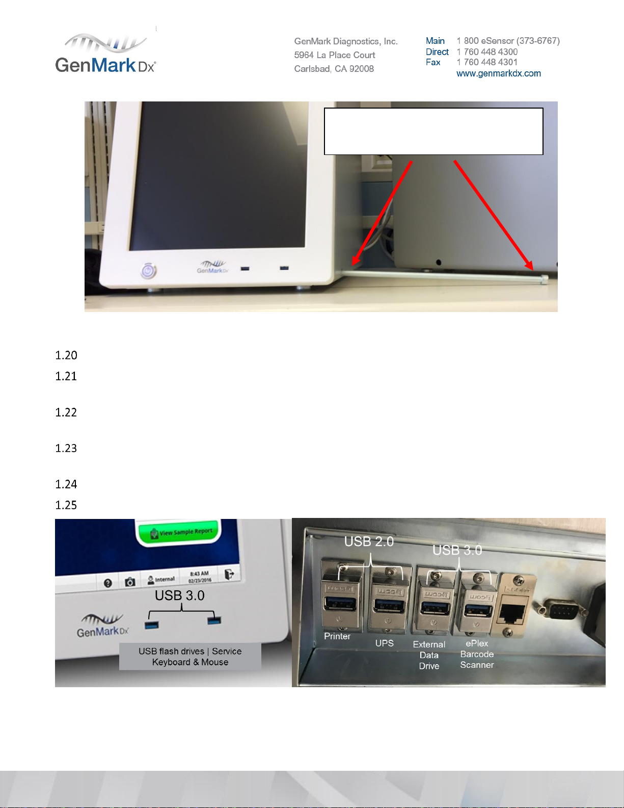
Insert the bootable USB (flash) drive with the Acronis image file into an ePlex USB port.
Power on the ePlex system and press and HOLD the Delete key on the keyboard to enter the BIOS
setup. Type the BIOS password if one has been preset. Otherwise, leave the password box blank and
click the Enter key.
Use the LEFT/RIGHT arrow keys on the keyboard to navigate to the Boot tab.
Use the UP/DOWN arrow keys on the keyboard to navigate to Boot Option #1 under FIXED BOOT
ORDER Priorities.
Press Enter and use the UP/DOWN arrow keys to navigate to USB Key as the Boot Option #1. If the
USB key does not have the description of the device, select the USB Floppy instead (which has the
description).
Press Enter then F4 to save these settings.
Select Yes in the Save & Exit Setup prompt and press Enter to temporarily boot from the USB (flash)
drive.
Note: The ePlex Instrument will reboot and should boot into Acronis True Image Software automatically
In the Acronis True Image screen, select Acronis True Image (select the first option).
Click the Recovery drop-down and select Disk and Partition Recovery.
In the Recovery Wizard, click the Browse button on the bottom right.
Navigate to the USB (flash) drive, browse to the ePlex X.X folder (where X.X is the version of the
image file), select the first volume file which ends with _v1.tib extension, and click the OK button.
Click the Next button once the full backup file is selected.
Select the Recover whole disks and partitions radio button and click the Next button.
Select the Disk 1 or Disk 2 checkbox, ensuring that all checkboxes under it are checked. Click the
Next button, then Next again.
Click the OK button on the Confirmation screen.
Click the Proceed button in the Summary screen.
Once the Data Recovery process has been completed, click OK to close the information prompt.
Remove the USB (flash) drive and click the Xbutton (red button with a white X on the upper right) to
reboot the PC.
As the ePlex system starts, press and HOLD the Delete key on the keyboard to enter the BIOS setup.

GNMK-IMC-6072-A
Use the LEFT/RIGHT arrow keys on the keyboard to navigate to the Boot tab.
Use the UP/DOWN arrow keys on the keyboard to navigate to Boot Option #1 under FIXED BOOT
ORDER Priorities then hit Enter.
Use the UP/DOWN arrow keys to navigate to Hard Disk (INTEL SDD...).
Press Enter then F4 to save these settings.
Select Yes in the Save & Exit Setup prompt and click Enter to permanently boot from the hard drive.
It might be necessary to restart the computer to apply these changes.
After reboot, if ISW does not automatically initiate, click CTRL+Shift+F3. This will bring up kiosk mode.
Click “GNMKSW” to initiate ISW.
Shut down the instrument using ISW.
Set breaker switch to OFF position and unplug main power.
Note: Prior to installing ANY Tower, the main power should be OFF. Turning the power off will ensure the
Tower connections to the Base power distribution board do not arc.
Tower Installation
Remove the Tower from the shipping container and examine for signs of physical damage or loose
connections. Report any damage to technical support with images and serial numbers of effected
equipment.
Remove tape from the leveling feet
Remove exterior structural panels from the Tower(s) by loosening the rear thumb screws so they can
be replaced with cosmetic panels later.
Figure 3 Structural Side Panel
Remove tower fascia to inspect (wiggle) the sliders.

GNMK-IMC-6072-A
Examine each of the six PCB sliders (located at the back of the Tower), which are mounted on two
plastic shocks as shown in Figure 4 . If either shock is cracked or damaged, the PCB slider will not be
seated securely and can impair proper connection to the bay. Examine shocks from both sides of the
Tower. Report damaged shocks as Tower OOBF to Technical Support; request an RMA and
replacement Tower from Customer Service.
Figure 4 PCB Slider and Shocks
To inspect the sliders, reach into the Tower slot and strongly wiggle the slider up and down and side
to side. There should be a fair amount of tension on the shock mounts. If the mounts can move easily
in any direction, the Tower will need replacement.
Verify that the washable filter is on the rear panel of each Tower.
If configuration is an NP, please continue to refer to the 3 Bay (NP) installation instructions to set
PCBA slider positions.
Locate the ePlex bay slots in the tower, these will be referred to as numbers 1 –6 from top to bottom
(see Figure 5 for reference).
Note: ePlex bay slot positions 1, 3, and 5 will be populated with bays.
•Bay position 3 will become electronic system position 2
•Bay position 5 will become electronic system position 3
•Bay position 1 DOES NOT CHANGE (remains electronic system position 1)
•ePlex bay slots 2, 4, and 6 will be left empty.

GNMK-IMC-6072-A
Figure 5 Bay slot positions
To allow the ISW to properly connect, the switch positions on the slider PCBA’s within the tower
positions need to be changed. Refer to Figure 7 for the NP Tower switch configuration.
Using a switch tool or similar, change the switch configuration of PCBA position 3 and PCBA position
5 to match Figure 7.

GNMK-IMC-6072-A
Figure 6 Position 3 and 5 Switch Location
Figure 7 NP Switch positions 1 –6
Bottom out the front Tower feet on the bottom of the tower.
Position Tower(s) on the work bench next to the Base using one of the available positioning options
for ePlex Base-Tower configuration shown in Figure 8. Configuration should be based on number of
towers, space available, and customer preference.

GNMK-IMC-6072-A
Figure 8 ePlex Tower Configurations
Cut the zip ties around the cables, route and connect the following.
•Power cable(s) to Base Power Distribution Board
•Grounding cable(s) from Tower grounding bolt(s) to Base grounding bolt(s).
•Ethernet cable(s) to Base Ethernet Switch
If installing a four (4) Tower system, or a two (2) Tower system with both towers on the right-hand
side, Tower position D’s power cable needs to have added strain relief.
See the following images for an understanding of the cable routing and connection process.
Figure 9 Tower cable routing positions

GNMK-IMC-6072-A
Figure 10 Power and Ethernet Cable
Figure 11 Connecting Base and Towers
Note: There are two grounding bolts mounted horizontally to the roof of the Base, one on each side. Each
Tower has one grounding bolt mounted on its rear side. Grounding cables should be routed directly from
each Tower to the Base.

GNMK-IMC-6072-A
Figure 12 Current Power Connector w/o tie wrap on position 4(D)
Thread a six-inch (6”) cable tie between the positive and negative wires of Tower D’s power cable.
(Figure 13)
Figure 13 Cable tie on power connector
Connect the power connector to the mating receptacle on the power distribution board and thread
the cable tie through the metal leads of the connector that is soldered to the power distribution
board. (Figure 14)
Figure 14 Properly tie wrapped power connector

GNMK-IMC-6072-A
Ensure both ends of each wire or cable are firmly in place.
Install and secure the structural panels to Base and Tower(s). (This should be done prior to attaching
the cabling/wiring due to risk of pulling and damaging the connections)
Attached the 3 bolts to connect the Tower(s) to the Base using the appropriate bolt (M10) and fasten
and secure the Tower(s) to the Base with an 8mm torque wrench set to 2.0 N⋅m or 15.0 lb⋅in. Visually
inspect after securing bolts to ensure Tower isn’t bent. If bent, consult Technical Support.
Note: Tighten per the torque specification to avoid damaging the Tower.
System Leveling
Level each Tower independently and start with a Tower closest to the Base by placing the dual axis
digital level in each bay position (Bubble levels are visual placeholders ONLY)
Figure 15 Dual axis level in empty bay slots within Tower
Level the Tower as close to 0° across all bay positions as possible in both directions by extending the
outermost 4 feet on the base and tower.
Note: The inner feet will likely float during this step which is acceptable and will ensure entire system can
be adjusted using just the 4 outer corner feet. All floating feet will be extended during step 22.8.
Note: For configurations with 2 Towers on a single side, level the closest Tower to the Base then level the
outer Tower. Ensure every tower is on a similar horizontal plane to each other so leveling one tower does
not adversely impact other towers. Loosening the bolts slightly may be required to adjust both towers
within level range. Make sure to re-torque the bolts after leveling is completed and recheck the level
after torqueing the bolts.

GNMK-IMC-6072-A
Figure 16 Acceptable Leveling Range from −00.25° to +00.70° (X-axis, left potentially high) and 0° to
-00.70° (Y-axis, back high)
Repeat steps 4.1 - 4.2 for additional towers as needed.
Bay Installation
Check the shipper to ensure the correct number of Bays have been delivered.
Note: If spare bays were shipped or trunk stock bays are available, DO NOT use unless any of the primary
shipped bays are OOBF.
Inspect the packing materials for any signs of physical damage.
Remove the Bays from their respective boxes, one at a time. Inspect each Bay.
Check all visible cabling and tubing for signs of distress, breaks, and disconnections.
Note: If damage is observed, do not install the Bay. Contact GenMark Technical Support for guidance.
Check blister motor lead screw nut and tighten if necessary. See Figure 17 below.
e
P
l
e
x

GNMK-IMC-6072-A
Figure 17 Bay Lead Screw Nuts
Clean the inside of each bay using compressed air.
Check all bays for debris and ‘chads’ inside the bay. Remove if found.
Figure 18 Label ‘chad’ stuck on top of bay
Check the high-density (HD) connector on each Bay to ensure they are seated properly. Press down
on both sides to tighten if necessary. Ensure HD connectors are fully pressed into place with no gold
showing. Note: It may be necessary to work the HD connector by pressing down with even pressure
in the back, followed by even pressure in the front, repetitive times, or until the gold contacts are no
longer visible. See Figure 19 and 21 below.

GNMK-IMC-6072-A
Figure 19 Clean Bay (1) and Check High Density Connector (2)
Notice the spacing
difference
Ensure the rear HD
connector is fully seated
Notice the spacing
difference
Ensure the rear HD
connector is fully seated
Figure 20 Tilted and disconnected HD connector board
Inspect gaskets for debris and clean the rubber gaskets, use a long swab and Isopropyl
alcohol or Ethanol to carefully clean the top surface of the black rubber gasket
Note: Take caution to NOT move the gasket out of place when cleaning.
Figure 21 Debris on rubber gasket
Inspect the tubing connection points on the solenoid valve.

GNMK-IMC-6072-A
Figure 22 Tubing assembly routing
If the tubing is assembled incorrectly, reseat the tubing, ensuring the tube face is flush against the
valve wall, and the service loop in the tubing is roughly parallel to the main PCBA.
Bays should sit at room temperature for approximately 30 minutes or more to ensure that the OQ
does not fail due to temperature gradients from shipping/storage temperatures.
Insert the Bay into an empty slot in the Tower.
Note: Light force may be required to properly seat a bay
Secure the Bay with a ¼ turn to the lock bolts on each side of the Bay using a #M3 hex wrench.
Repeat steps 5.4 - 5.14 for each Bay.
If a Bay cannot be properly installed, record the serial number, process a RMA (contact Technical
Set the Bay dip switches with the approved tool according to Figure 23 and Figure 24 below for each
Bay according to its location.
Note: Each Tower position is based on the physical position of the Tower as laid out in Figure 8.
Correct assembly
Notice the gap between the
tubing and valve body, and the
radial bend of the tubing

GNMK-IMC-6072-A
Figure 23 Bay Dip Switch Location
Figure 24 Bay Dip Switch Settings
Plug in the main power cord to the Base and flip the rear power switch to the ON/up/”I” position.
Power up the system by turning on the rear power switch and pressing the Base front power button.
Verify the system will power on.
Confirm each Bay is fully powered and connected to the system by checking the rear LEDs, which
should be lit (pink in beta bays and brighter in production bays). See Figure 25 below.
TowerPosition
DipswitchPosition
1
2
3
4
1
On
On
On
On
2
On
On
On
On
3
On
On
On
On
4
On
On
On
On

GNMK-IMC-6072-A
If you do not see the pink light, take the Bay out and wait 3 minutes before placing it back in the
system.
Figure 25 Bay Power & Communication Indicator LED (3)
Ensure all Bays installed have connected to the system, as indicated by flashing red LEDs.
Note:If Bays are not connected, the LEDs at the front of the Bay will not flash red and the status in the
Bay Configuration tab will indicate they cannot connect to the system.
Note:The OS will need to be configured in Windows to reflect the correct IP address to connect the Bays
to the system.
Note:If Bay LED lights are not on, ensure the dip switches are in the correct position per Figure 24.
Press Ctrl + Shift + F3 on the keyboard and logon under the ‘GNMK Service’account to access the
Windows Operating System.
Check the time zone, date and time and update as necessary based on customer location.
Configure OS Settings
In Windows, go to Start > Control Panel > Network and Sharing Center
In Network and Sharing Center, select Change adapter settings.
Right click on the highest Local Area Connection (Local Area Connection 2 in Figure 26 below) and
select Properties.
Select Internet Protocol Version 4 (TCP/IPv4).
Click the Properties button and ensure the static IP address is properly configured:
IP Address must be 10.10.100.XX (XX must be a number higher than 25, i.e. 26).
Subnet mask must be 255.255.255.0
Press OK > Close > Close again

GNMK-IMC-6072-A
Figure 26 IP Configuration Setting
Select the Start icon then navigate to Computer and right click, select Properties
Figure 27 System properties
Select Change Settings to open System Properties.

GNMK-IMC-6072-A
Figure 28 Change System Settings
Under the Computer Name tab, click Change to open the Computer Name/Domain Changes window.
Figure 29 Computer Name
Change the computer name as defined in the naming convention below.
•Default Computer Name: ePlex00000
•New Computer Name: i.e. ePlex1640100124 (must be changed to the 10-digit Base serial number)
Other manuals for ePlex
1
Table of contents