Aesculap GB176R Manual
Aesculap®Acculan 4
Aesculap Power Systems
en Instructions for use/Technical description
Attachments
USA Note for U.S. users
This Instructions for Use is NOT intended for United States users. Please
discard. The Instructions for Use for United States users can be obtained
by visiting our website at www.aesculapusa.com and clicking the "Prod-
ucts" menu. If you wish to obtain a paper copy of the Instructions for Use,
you may request one by contacting your local Aesculap representative or
Aesculap's customer service at 1-800-282-9000. A paper copy will be
provided to you upon request at no additional cost.
de Gebrauchsanweisung/Technische Beschreibung
Aufsätze
fr Mode d’emploi/Description technique
Embouts
es Instrucciones de manejo/Descripción técnica
Cabezales
it Istruzioni per l’uso/Descrizione tecnica
Terminali
pt Instruções de utilização/Descrição técnica
Cabeçotes
nl Gebruiksaanwijzing/Technische beschrijving
Opzetstukken
sv Bruksanvisning/Teknisk beskrivning
Tillsatser
fi Käyttöohje/Tekninen kuvaus
Istukat
et Kasutusjuhend/Tehniline kirjeldus
Otsakud
ru Инструкция по примению/Техническое описание
Насадки
cs Návod k použití/Technický popis
Násadce
pl Instrukcja użytkowania/Opis techniczny
Nasadki
sk Návod na použitie/Technický opis
Nadstavec
tr Kullanım Kılavuzu/Teknik açiklama
Başlıklar

1
2 3
4 567
8
97
8
12
8
13
17
20
8
21
22
23
24
19
18
8
1011
14
16
15
15
8
8
GB621R
GB641R
GB660R
A
B
C
25
18
19
17
26
GB184R
XF457R
GB667R
GB657R
GB628R
GB176R
GB623R
GB663R
GB664R
GB665R
GB620R
GB639R
GB645R GB668R
GB669R
GB670R
2
en
Aesculap®Acculan 4
Attachments
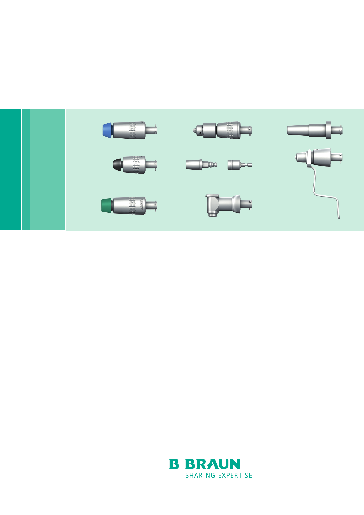
Legend
1Drill
2Knob (for speed control)
3Safety catch
4Rotating sleeve
5Arrow
6Reamer attachment with quick-action chuck adapter
7Unlocking sleeve
8Tool coupling
9Drill attachment with quick-action chuck adapter
10 Drill attachment keyless Jacobs chuck
11 Locking sleeve
12 Attachment with Jacobs chuck
13 Tightening key
14 Zimmer chuck with Hudson/Zimmer coupling
15 Unlocking sleeve
16 Adapter AO large to DHS/DCS step drill
17 Sagittal saw attachment
18 Tool attachment with L sagittal tool coupling
19 Knob for tool release
20 Drill attachment for Synthes radiolucent angle transmission
21 Kirschner wire attachment
22 Clamping lever
23 Adjustment sleeve
24 Kirschner wire chuck
25 L sagittal saw blade
26 Oil spray adapter
The diagrams are only schematic.
Symbols on product and packages
Contents
1. Applicable to . . . . . . . . . . . . . . . . . . . . . . . . . . . . . . . . . . . . . . . . 3
2. General information . . . . . . . . . . . . . . . . . . . . . . . . . . . . . . . . . . 3
2.1 Intended use . . . . . . . . . . . . . . . . . . . . . . . . . . . . . . . . . . . . . . . . 3
2.2 Main functions and design characteristics. . . . . . . . . . . . . . . . 3
2.3 Indications. . . . . . . . . . . . . . . . . . . . . . . . . . . . . . . . . . . . . . . . . . 4
2.4 Absolute contraindications . . . . . . . . . . . . . . . . . . . . . . . . . . . . 4
2.5 Relative contraindications . . . . . . . . . . . . . . . . . . . . . . . . . . . . . 4
3. Safe handling . . . . . . . . . . . . . . . . . . . . . . . . . . . . . . . . . . . . . . . 4
4. Product description. . . . . . . . . . . . . . . . . . . . . . . . . . . . . . . . . . . 4
4.1 Scope of supply. . . . . . . . . . . . . . . . . . . . . . . . . . . . . . . . . . . . . . 4
4.2 Components required for operation . . . . . . . . . . . . . . . . . . . . . 4
4.3 Operating principle . . . . . . . . . . . . . . . . . . . . . . . . . . . . . . . . . . . 4
5. Preparation . . . . . . . . . . . . . . . . . . . . . . . . . . . . . . . . . . . . . . . . . 4
6. Working with the device . . . . . . . . . . . . . . . . . . . . . . . . . . . . . . 5
6.1 System set-up . . . . . . . . . . . . . . . . . . . . . . . . . . . . . . . . . . . . . . . 5
6.1.1 Connecting the accessories . . . . . . . . . . . . . . . . . . . . . . . . . . . . 5
6.2 Protection against inadvertent activation . . . . . . . . . . . . . . . . 5
6.3 Coupling and uncoupling of attachment to drill and reamer . 5
6.4 Attaching and detaching the tool from the attachment. . . . . 5
6.4.1 Attachments with quick-action chuck GB623R/GB657R/
GB663R/GB664R/GB665R/GB668R/GB669R/GB670R. . . . . . . 5
6.4.2 Drill attachment keyless Jacobs chuck GB620R. . . . . . . . . . . . 5
6.4.3 Attachments with three-jaw chuck GB621R/GB639R/GB667R 6
6.4.4 Zimmer chuck with Hudson/Zimmer shaft GB176R. . . . . . . . . 6
6.4.5 Harris chuck with AO large shaft GB184R and DIN chuck with
AO large shaft XF457R . . . . . . . . . . . . . . . . . . . . . . . . . . . . . . . . 6
6.4.6 Adapter AO large to DHS/DCS step drill GB628R. . . . . . . . . . . 6
6.4.7 Sagittal saw attachment GB660R . . . . . . . . . . . . . . . . . . . . . . . 6
6.4.8 Drill attachment for Synthes radiolucent angle transmission
GB645R . . . . . . . . . . . . . . . . . . . . . . . . . . . . . . . . . . . . . . . . . . . . 6
6.4.9 Insert and clamp Kirschner wire attachment GB641R. . . . . . . 6
6.5 Function checks . . . . . . . . . . . . . . . . . . . . . . . . . . . . . . . . . . . . . 7
6.6 Safe operation. . . . . . . . . . . . . . . . . . . . . . . . . . . . . . . . . . . . . . . 7
7. Validated reprocessing procedure . . . . . . . . . . . . . . . . . . . . . . . 8
7.1 General safety notes. . . . . . . . . . . . . . . . . . . . . . . . . . . . . . . . . . 8
7.2 General information . . . . . . . . . . . . . . . . . . . . . . . . . . . . . . . . . . 8
7.3 Preparations at the place of use . . . . . . . . . . . . . . . . . . . . . . . . 8
7.4 Preparation before cleaning. . . . . . . . . . . . . . . . . . . . . . . . . . . . 8
7.5 Cleaning/disinfection . . . . . . . . . . . . . . . . . . . . . . . . . . . . . . . . . 8
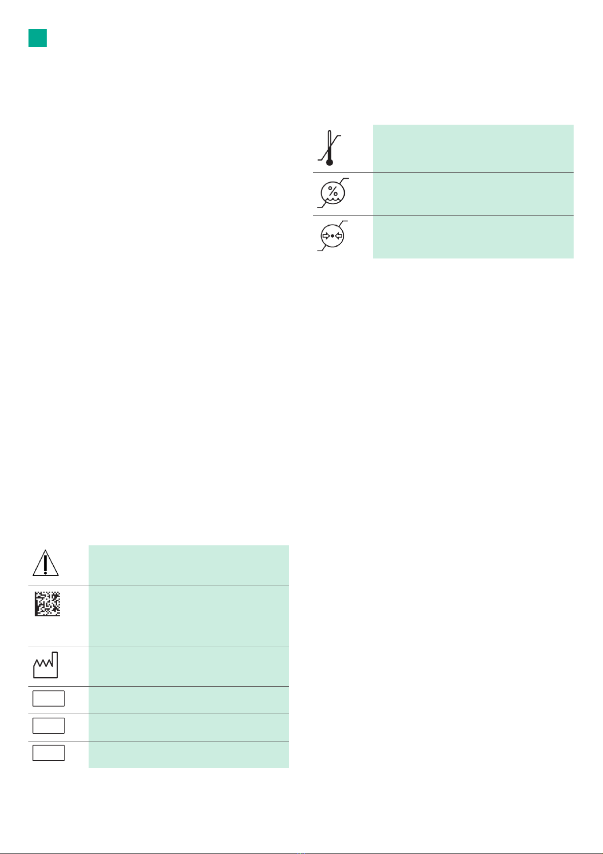
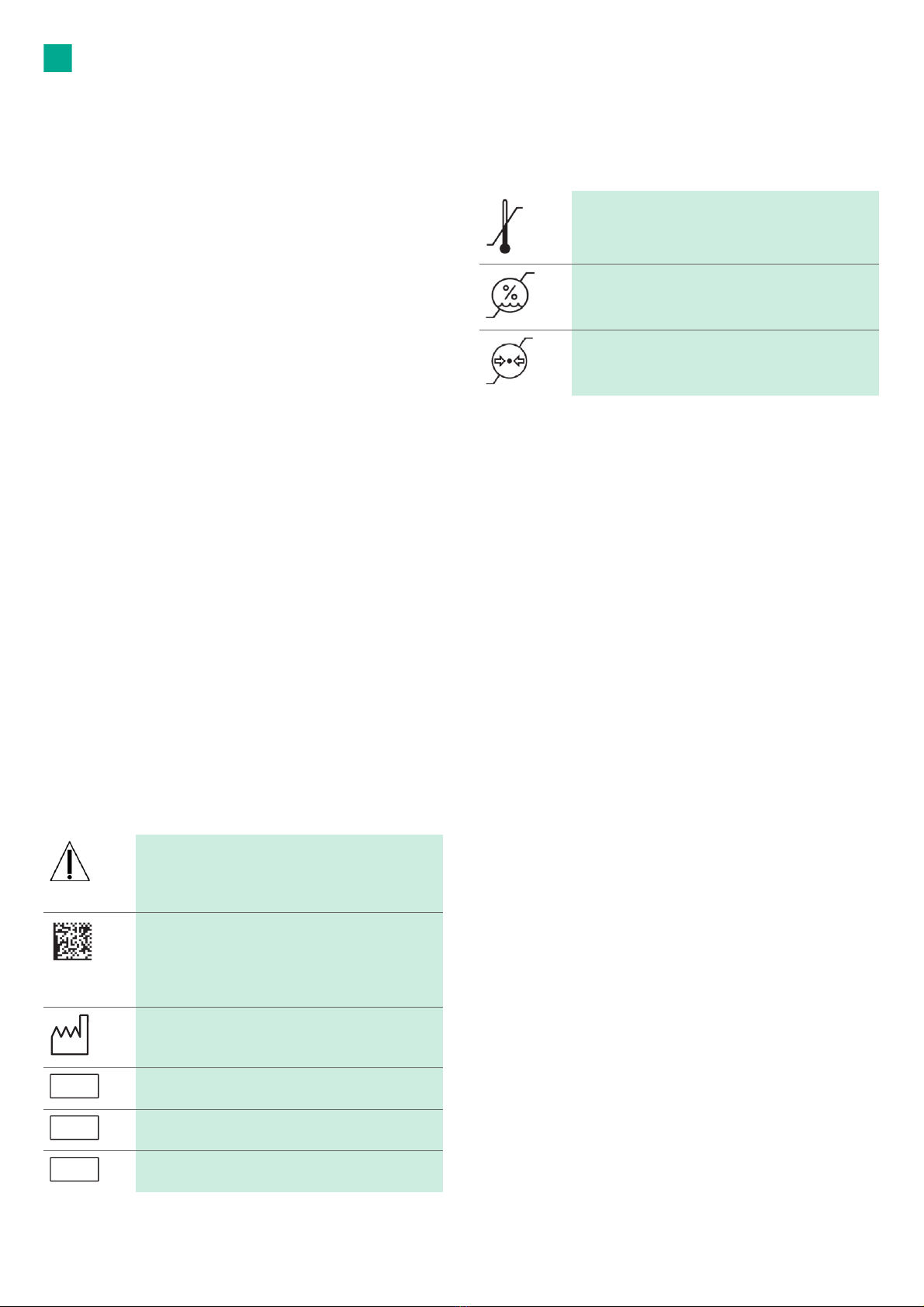
Caution
Observe important safety information such as warn-
ings and precautions in the instructions for use.
Machine-readable, two-dimensional code
The code contains a unique serial number which can be
used for electronic tracking of the individual instru-
ment. The serial number is based on the global stan-
dard sGTIN (GS1).
Date of manufacture
Manufacturer’s batch designation
Manufacturer’s serial number
Manufacturer’s article number
LOT
SN
REF
Temperature limits during transport and storage
Air humidity limits during transport and storage
Atmospheric pressure limits during transport and stor-
age

3
en
7.5.1 Product-specific safety instructions for the reprocessing
procedure . . . . . . . . . . . . . . . . . . . . . . . . . . . . . . . . . . . . . . . . . . . 8
7.6 Manual cleaning with wipe disinfection . . . . . . . . . . . . . . . . . . 9
7.7 Automatic cleaning/disinfection with manual pre-cleaning . . 10
7.7.1 Manual pre-cleaning with a brush. . . . . . . . . . . . . . . . . . . . . . . 10
7.7.2 Mechanical alkaline cleaning and thermal disinfection. . . . . . 11
7.8 Inspection, maintenance and checks . . . . . . . . . . . . . . . . . . . . . 11
7.9 Packaging . . . . . . . . . . . . . . . . . . . . . . . . . . . . . . . . . . . . . . . . . . . 11
7.10 Steam sterilization. . . . . . . . . . . . . . . . . . . . . . . . . . . . . . . . . . . . 11
7.11 Storage . . . . . . . . . . . . . . . . . . . . . . . . . . . . . . . . . . . . . . . . . . . . . 11
8. Maintenance . . . . . . . . . . . . . . . . . . . . . . . . . . . . . . . . . . . . . . . . 11
9. Troubleshooting list . . . . . . . . . . . . . . . . . . . . . . . . . . . . . . . . . . . 12
10. Technical Service . . . . . . . . . . . . . . . . . . . . . . . . . . . . . . . . . . . . . 13
11. Accessories/Spare parts. . . . . . . . . . . . . . . . . . . . . . . . . . . . . . . . 13
12. Technical data . . . . . . . . . . . . . . . . . . . . . . . . . . . . . . . . . . . . . . . 13
12.1 Classification acc. to Directive 93/42/EEC. . . . . . . . . . . . . . . . . 13
12.2 Performance data, information about standards . . . . . . . . . . . 13
12.3 Operating mode . . . . . . . . . . . . . . . . . . . . . . . . . . . . . . . . . . . . . . 15
12.4 Environmental conditions . . . . . . . . . . . . . . . . . . . . . . . . . . . . . . 15
13. Disposal . . . . . . . . . . . . . . . . . . . . . . . . . . . . . . . . . . . . . . . . . . . . 15
1. Applicable to
►For item-specific instructions for use and information on material
compatibility, see also the Aesculap Extranet at
https://extranet.bbraun.com
2. General information
2.1 Intended use
Task/Function
The drill and milling machines GA330, GA671 and GA672, combined with
the corresponding attachments and tools, are used to process hard tissue,
cartilage, cognate and bone replacement materials, inserting and remov-
ing bone pins as well as for inserting transfixion wires.
Application Environment
The product is used in operating rooms in sterile zones outside of the
explosion risk zone (such as areas with pure oxygen or anesthesia gases).
2.2 Main functions and design characteristics
Speed GB667R
GB668R
GB669R
GB670R
0 min-1 to max. 250 min-1
GB657R 0 min-1 to max. 370 min-1
GB645R 0 min-1 to max. 900 min-1
GB620R
GB621R
GB663R
GB664R
GB665R
0 min-1 to max. 1 000 min-1
GB623R
GB639R
GB641R
0 min-1 to max. 1 250 min-1
GB660R 0 min-1 to max. 17 000 min-1
Rotational direc-
tion
Right and left rotation, oscilla-
tion
Operating mode Operation with non-periodic
load and speed changes (type
S9 pursuant to IEC EN 60034-
1)
Right/left rotation:
■60 second application,
60 second pause
■20 repetitions
■30 min cooling time
■Max. Temperature 48 °C
Milling (clockwise/counter-
clockwise):
■30 second application,
30 second pause
■8 repetitions
■30 min cooling time
■Max. Temperature 48 °C
Drilling (oscillation):
■60 second application,
60 second pause
■4 repetitions
■30 min cooling time
■Max. Temperature 48 °C
Saw mode with GB660R:
■30 second application,
60 second pause
■3 repetitions
■30 min cooling time
■Max. Temperature 48 °C
4
en
2.3 Indications
The type and area of application depend on the tool selected.
2.4 Absolute contraindications
The product is not licensed for use on the central nervous system or central
circulatory system.
2.5 Relative contraindications
The safe and effective use of the product greatly depends on influences
which can only be controlled by the user. Therefore the specifications pro-
vided represent framework conditions only.
Clinically successful use of the product is dependent on the knowledge and
experience of the surgeon. The surgeon must decide which structures it is
sensible to treat and take into account the safety and warning information
contained in these instructions for use.
3. Safe handling
■General risk factors associated with surgical procedures are not
described in this documentation.
■It is the operating surgeon's responsibility to ensure that the surgical
procedure is performed correctly.
■The operating surgeon must have a thorough understanding of both the
hands-on and conceptual aspects of the established operating tech-
niques.
►Remove the transport packaging and clean the new product, either
manually or mechanically, prior to its initial sterilization.
►Prior to use, check that the product is in good working order.
►To prevent damage caused by improper setup or operation, and in order
not to compromise warranty and manufacturer liability:
– Use the product only according to these instructions for use.
– Follow the safety and maintenance instructions.
– Only combine Aesculap products with each other.
►Ensure that the product and its accessories are operated and used only
by persons with the requisite training, knowledge, or experience.
►Keep the instructions for use accessible for the user.
►Always adhere to applicable standards.
►Ensure that the electrical installation of the room is consistent with the
requirements of IEC/DIN EN.
►Do not operate the product in explosion-hazard areas.
►Sterilize product before use.
►When handling, observe instructions for use that are relevant to
Aesculap holder systems TA009721, see Aesculap Extranet at
https://extranet.bbraun.com
4. Product description
4.1 Scope of supply
4.2 Components required for operation
■Drill and reamer GA330 (ready)
–or-
■Acculan 3Ti Drill and milling machine GA672 (ready for operation)
–or-
■Acculan 3Ti Small drill GA671 (ready for operation)
■Tool (depending on indication)
4.3 Operating principle
The attachment can be coupled to the drill and reamer in three different
positions, each offset by 120°.
The attachment locks automatically when attached to the drill and reamer.
The attachment can be removed by operating a rotating sleeve on the drill
and reamer.
The attachments have various integrated couplings on the working end, to
enable attachment of various tools, Kirschner wires or adapters.
5. Preparation
Aesculap assumes no liability if the following rules are not followed:
►Do not use products from open or damaged sterile packaging.
►Prior to use, inspect the product and its accessories for any visible dam-
age.
►Use the products and their accessories only if they are in perfect tech-
nical condition.
WARNING
Risk of injury and material damage due to inappro-
priate use of the product!
►Use the product only in accordance with the
intended purpose.
WARNING
Risk of injury and damage to property due to
improper handling of the product!
►Follow the instructions for use of all products
used.
Art. no. Designation
GB176R
GB184R
GB620R
GB621R
GB623R
GB628R
GB639R
GB641R
GB645R
GB657R
GB660R
GB663R
GB664R
GB665R
GB667R
GB668R
GB669R
GB670R
XF457R
One of the following attachments/adapters:
Zimmer chuck with Hudson/Zimmer shaft
Harris chuck with AO large shaft
Drill attachment keyless Jacobs chuck
Drill attachment large Jacobs chuck
Drill attachment AO small
Adapter AO large to DHS/DCS step drill
Drill attachment small Jacobs chuck
Kirschner wire attachment
Drill attachment for Synthes radiolucent angle trans-
mission
Medullary reamer attachment AO large
Sagittal saw attachment
Drill attachment Trinkle
Drill attachment Aesculap hexagon
Drill attachment Hudson/Zimmer
Reamer attachment large Jacobs chuck
Reamer attachment AO large
Reamer attachment Hudson/Zimmer
Reamer attachment Harris
DIN chuck with AO large shaft
GA031R Chuck key for large Jacobs chuck (GB620R, GB621R
and GB667R)
GA062R Key for small Jacobs chuck (GB639)
TA014541 Instructions for use for Acculan 4 attachments (flyer)
5
en
6. Working with the device
6.1 System set-up
6.1.1 Connecting the accessories
Combinations of accessories that are not mentioned in the present
instructions for use may only be employed if they are specifically intended
for the respective application, and if they do not compromise the perfor-
mance and safety characteristics of the products.
All configurations must fulfill the fundamental standard
IEC/DIN EN 60601-1. The person connecting the devices with each other
is responsible for the configuration and must ensure that the fundamental
standard IEC/DIN EN 60601-1 or relevant national standards.
►Follow the instructions for use of individual accessories.
►Please address your B. Braun/Aesculap partner or Aesculap Technical
Service with any inquiries in this respect; for a contact address, see
Technical Service.
6.2 Protection against inadvertent activation
The rotational speed control button can be locked to prevent inadvertent
activation of the drill and reamer during a tool/attachment change.
Locking the knob for speed control 2:
►Twist the safety catch 3to position OFF.
The speed control knob 2is blocked and the product 1cannot be oper-
ated.
Unlocking the knob for speed control 2:
►Twist the safety catch 3to position ON.
The speed control knob 2is unlocked and the product 1can be oper-
ated.
Note
For further information on the drill and reamer, see TA014538 or TA014539
(flyer).
6.3 Coupling and uncoupling of attachment to drill
and reamer
►Secure drill and reamer 1against inadvertent activation with the
safety catch 3, see Protection against inadvertent activation.
Coupling
►Push the attachment onto drill and reamer 1until it engages with a
click.
►Pull at attachment to check that it is securely coupled.
Uncoupling
►Turn the sleeve 4in the direction of the arrow 5and simultaneously
remove the attachment from the drill and reamer 1.
6.4 Attaching and detaching the tool from the attach-
ment
►Ensure that the tool connector and attachment type are compatible.
6.4.1 Attachments with quick-action chuck GB623R/GB657R/
GB663R/GB664R/GB665R/GB668R/GB669R/GB670R
Coupling
►Pull back on the unlocking sleeve 7.
►Insert the tool shaft in the correct position up to the stop in the tool
holder 8of the attachment 6/9.
►Release the unlocking sleeve 7.
Tool is attached.
►Pull at tool to check that it is securely coupled.
Uncoupling
►Pull back the unlocking sleeve 7.
►Remove tool.
6.4.2 Drill attachment keyless Jacobs chuck GB620R
Note
The drill attachment keyless Jacobs chuck GB620R may open during left-
hand rotation of tools (e.g. when pulling out tools).
To operate tools in left-hand rotation, use the Jacobs chuck with key
GB621R, GB639R or GB667R.
Note
If necessary, the key GA031R can be used for coupling and decoupling.
Coupling
►Rotate the locking sleeve 11 clockwise and open Jacobs chuck.
►Insert the tool shaft in the correct position up to the st op in the tool
holder 8of the attachment 10.
►Rotate locking sleeve 11 counterclockwise and close Jacobs chuck.
►Pull at tool to check that it is securely coupled.
WARNING
Risk of infection and contamination!
Product is delivered unsterilized!
►Sterilize the product before use pursuant to the
operating instructions.
WARNING
Risk of injury and material damage due to inappro-
priate use of tools!
►Always follow the safety advice and information
given in the instructions for use.
►When coupling/uncoupling, handle tools with
cutting edges with care.
WARNING
Damage to the product if dropped!
►Use the products only if they are in perfect tech-
nical condition, see Function check
WARNING
Risk of burns to skin and tissue through blunt tools
or if product has not been maintained properly!
►Use tools only if they are in perfect condition.
►Replace blunt tools.
►Maintain the product properly, see maintenance
guide.
DANGER
Risk of injury due to unapproved configuration
using additional components!
►Ensure that the classification of all components
used is consistent with the classification of the
product (such as type BF or type CF).
WARNING
Risk of injury when attaching/removing attach-
ments/tools in the ON position through inadvertent
activation of the product!
►Only attach/remove attachments/tools in the
OFF position.
WARNING
Risk of injury when attaching/removing attach-
ments/tools in the ON position through inadvertent
activation of the product!
►Only attach/remove attachments/tools in the
OFF position.

6
en
Uncoupling
►Rotate the locking sleeve 11 clockwise and open Jacobs chuck.
►Remove tool.
►Rotate the locking sleeve 11 counterclockwise and close Jacobs chuck.
6.4.3 Attachments with three-jaw chuck
GB621R/GB639R/GB667R
Coupling
►Open the Jacobs chuck with the key 13.
►Insert the tool shaft in the correct position up to the st op in the tool
holder 8of the attachment 12.
►Close the Jacobs chuck with the key 13 and pull tight.
►Pull at tool to check that it is securely coupled.
Uncoupling
►Open the Jacobs chuck with the key 13.
►Remove tool.
6.4.4 Zimmer chuck with Hudson/Zimmer shaft GB176R
Coupling
►Push unlocking sleeve forward 15 and hold.
►Insert the tool shaft in the correct position up to the st op in the tool
holder 8of the attachment 14.
►Release the unlocking sleeve 15.
►Pull at tool to check that it is securely coupled.
Uncoupling
►Push unlocking sleeve forward 15 and hold.
►Remove tool.
6.4.5 Harris chuck with AO large shaft GB184R and DIN chuck with
AO large shaft XF457R
Coupling
►Push unlocking sleeve back 15 and hold.
►Insert the tool shaft in the correct position up to the st op in the tool
holder 8of the attachment 14.
►Release the unlocking sleeve 15.
►Pull at tool to check that it is securely coupled.
Uncoupling
►Push unlocking sleeve back 15 and hold.
►Remove tool.
6.4.6 Adapter AO large to DHS/DCS step drill GB628R
Coupling
►Push unlocking sleeve back 15 and hold.
►Insert the tool shaft in the correct position up to the st op in the tool
holder 8of the attachment 16.
►Release the unlocking sleeve 15.
►Pull at tool to check that it is securely coupled.
Uncoupling
►Push unlocking sleeve back 15 and hold.
►Remove tool.
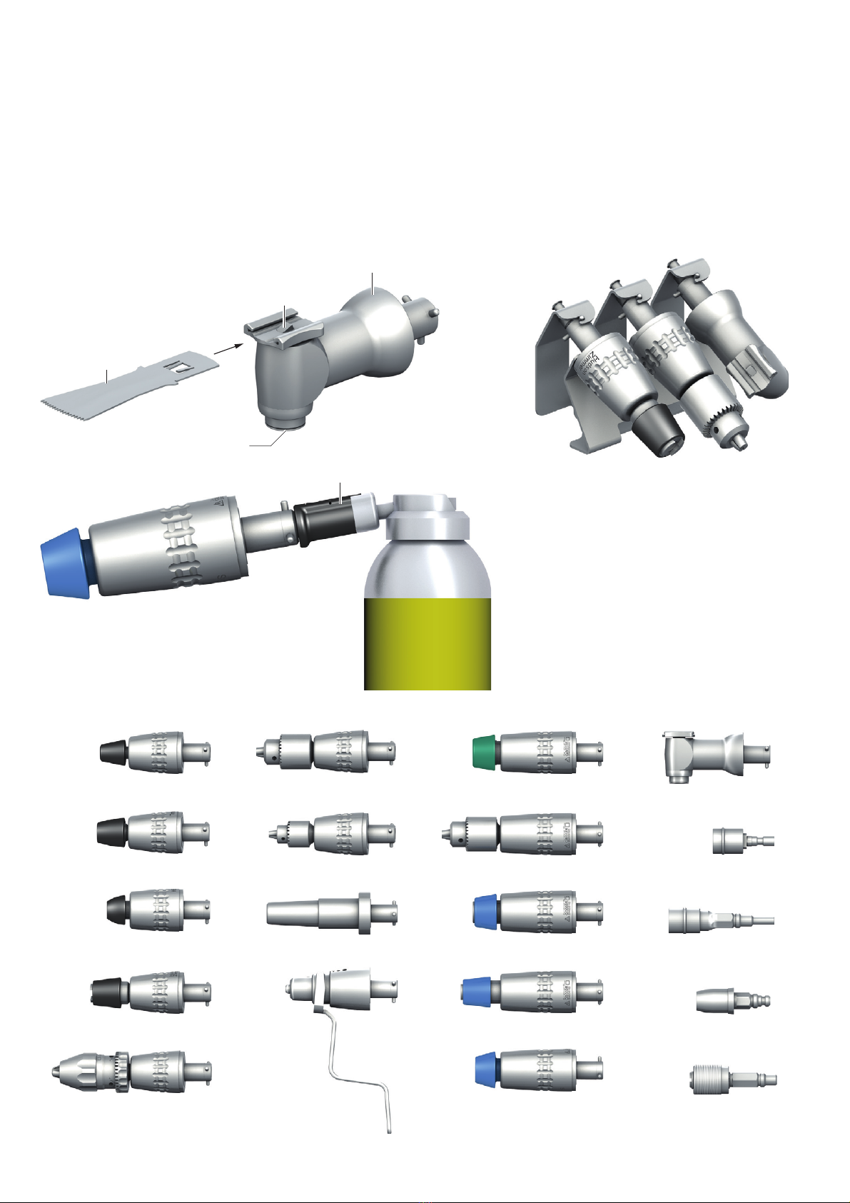
6.4.7 Sagittal saw attachment GB660R
Coupling
►Insert saw blade 25 into the slot of the tool holder 18, see Fig. A.
Ensure that the side stops of the saw blade are aligned with the tool
holder.
The tool engages.
►Pull on the attachment 22 to ensure a secure fit.
Uncoupling
►Press kjnob for tool release 19 and pull saw blade 25 out of the tool
holder 18.
6.4.8 Drill attachment for Synthes radiolucent angle transmission
GB645R
The drill attachment allows connecting a radiolucent angle transmission
for applying drill holes in the bone under radiographic control.
The drill attachment is only suitable for use of the radiolucent angle trans-
mission 511.300 from the Synthes company.
►Follow the instructions for the radiolucent angle transmission 511.300
in the operating instructions of the Synthes company.
Coupling the angle transmission
►Push the radiolucent angle transmission up to the stop on holder 8of
the drill attachment 20.
►If necessary, slightly move the radiolucent unit.
Decouple angled handpiece
►Forcefully pull out the radiolucent angle transmission from the drill
attachment 20.
Couple/decouple the tool
►Follow the instructions for the radiolucent angle transmission 511.300
in the operating instructions of the Synthes company.
6.4.9 Insert and clamp Kirschner wire attachment GB641R
Note
The special Kirschner wire chuck is recommended for the placement of
guide wires. This quick-action chuck adapter allows quick and easy ten-
sioning of drilling wires.
For further information see TA014535 or TA014539 (flyer).
The following diameters can be set on the Kirschner wire attachment:
■0.6 mm to 1.8 mm
■1.8 mm to 3.0 mm
■3.0 mm to 4.0 mm
Insert Kirschner wire
►Ensure that the clamping lever 22 is in the starting position (deacti-
vated status).
►Set the adjusting sleeve 23 of the Kirschner wire attachment to the
desired diameter range:
– Push back the adjusting sleeve 23 and turn until the desired diam-
eter range has been reached.
– Release adjustment sleeve 23, making certain that adjustment
sleeve 23 clicks into position.
►Insert the Kirschner wire into the Kirschner wire chuck 24 until the
desired exposed length is achieved.
The Kirschner wire is held in the intended position in the attachment
by an automatic clamping mechanism.
WARNING
Risk of injury when using long guide wires!
►Use Kirschner wire protection sleeve when using
long guide wires.

7
en
Clamping the Kirschner wire
►Pull on the clamping lever 22 and hold in the desired position.
The further the clamping lever is pulled back, the higher the tension of
the Kirschner wire.
Note
The Kirschner wire will only remain tensioned with the clamping lever
pulled back. If the clamping lever is released, it will move back into the
starting position and the Kirschner wire is freely mobile.
6.5 Function checks
The function test must be performed before each use and after each intra-
operative change of attachment and tool.
►Check that the attachment is coupled properly. To test this, pull on the
attachment.
►Check that the tool is coupled properly. To do this, pull on the tool.
►Ensure that the tool blades are not mechanically damaged.
►Release drill and reamer for use (ON position).
►Briefly run the drill and reamer at maximum speed in clockwise and
counterclockwise mode.
►Make certain that the rotational direction is correct in each case.
►Check the product for damage, abnormal operation noises, heavy vibra-
tion and excessive heat.
►Do not use the product if it is damaged or defective.
►Set aside the product if it is damaged.
6.6 Safe operation
Operating the product
Note
For further information on the drill and reamer, see TA014538 or TA014539
(flyer).
►Start the drill and reamer at moderate speed.
►Apply moderate pressure to prevent slipping.
►Do not bend the tool, otherwise there is a danger of breakage.
►When screwing bone screws and bone pins in and out: ensure correct
torque setting.
Use the following attachments for drilling:
■GB620R
■GB621R
■GB623R
■GB639R
■GB663R
■GB664R
■GB665R
Use the following attachments for milling (medullary reaming):
■GB667R
■GB668R
■GB669R
■GB670R
Use the following attachment for medullary reaming:
■GB657R
Use the following attachment for the placement of Kirschner wires:
■GB641R
Use only the following attachment for using the radiolucent angle trans-
mission 511.300 from the Synthes company:
■GB645R
Use the following attachment for drilling:
■GB660R
WARNING
Coagulation of patient tissue or risk of burns for
patients and user through hot product!
►Do not use drill attachments to operate reamer
tools such as the acetabulum reamer and the
medullary reamer.
►Operate any reamer tool only with a reamer
attachment.
►Cool the tool during operation.
►Keep product/tool out of the reach of patients.
►Let the product/tool cool down.
►Use a cloth to protect against burns when
changing the tool.
WARNING
Risk of infection or injury through aerosol forma-
tion or particles ejected from the tool!
►Use suitable protection (such as waterproof pro-
tective clothing, face mask, safety gases, suc-
tion).
WARNING
Risk of injury and/or malfunction!
►Always carry out a function check prior to using
the product.
WARNING
Risk of injury when using the product beyond the
field of view!
►Apply the product only under visual control.
WARNING
Risk of injury and damage to the tool/system!
The rotating tool may get caught in drapes (such as
textiles).
►Do not let the tool come into contact with
drapes (such as textiles) during operation.

8
en
7. Validated reprocessing procedure
7.1 General safety notes
Note
Adhere to national statutory regulations, national and international stan-
dards and directives, and local, clinical hygiene instructions for reprocess-
ing.
Note
For patients with Creutzfeldt-Jakob disease (CJD), suspected CJD, or possi-
ble variants of CJD, observe the relevant national regulations concerning
the reprocessing of products.
Note
Mechanical reprocessing should be favored overmanual cleaning as it gives
better and more reliable results.
Note
It should be noted that successful reprocessing of this medical device can
only be guaranteed following prior validation of the reprocessing method.
The operator/reprocessing technician is responsible for this.
The recommended chemistry was used for validation.
Note
If there is no final sterilization, then a virucidal disinfectant must be used.
Note
For up-to-date information about reprocessing and material compatibility,
see also the Aesculap Extranet at https://extranet.bbraun.com
The validated steam sterilization procedure was carried out in the Aesculap
sterile container system.
7.2 General information
Dried or affixed surgical residues can make cleaning more difficult or inef-
fective and lead to corrosion. Therefore the time interval between applica-
tion and processing should not exceed 6 h; also, neither fixating pre-
cleaning temperatures >45 °C nor fixating disinfecting agents (active
ingredient: aldehydes/alcohols) should be used.
Excessive neutralizing agents or basic cleaners may result in a chemical
attack and/or fading and the laser marking becoming unreadable either
visually or by machine.
On stainless steel, residues containing chlorine or chloride (such as surgi-
cal residues, drugs, saline solutions in water for cleaning, disinfection and
sterilization) may lead to corrosion (pitting corrosion, tensile corrosion)
and thus to the destruction of the product. These must be removed by rins-
ing thoroughly with demineralized water and then drying.
Perform additional drying, if necessary.
Only process chemicals that have been tested and approved (e.g. VAH or
FDA approval or CE mark) and which are compatible with the product’s
materials according to the chemical manufacturers’ recommendations
may be used for processing the product. All the chemical manufacturer's
application specifications must be strictly observed. Failure to do so can
result in the following problems:
■Visual material changes (such as fading or color changes in titanium or
aluminum). For aluminum, the application/process solution only needs
to be pH >8 to cause visible surface changes.
■Material damage (such as corrosion, cracks, breaks, premature aging or
swelling).
►Do not use metal cleaning brushes or other abrasives that would dam-
age the product surface and could cause corrosion
►For further detailed information on hygienically safe and material-pre-
serving/value-preserving reprocessing, see www.a-k-i.org, link to Pub-
lications, Red Brochure – Proper maintenance of instruments.
7.3 Preparations at the place of use
►Remove all attached components from the product (tool and accesso-
ries).
►Remove the attachment from drill and reamer.
►Remove any visible surgical residues as much as possible with a damp,
lint-free cloth.
►Place the dry product in a sealed waste container and forward it on for
cleaning and disinfection within 6 hours.
7.4 Preparation before cleaning
►Before the first automatic cleaning/disinfection: attach ECCOS fixa-
tions in a suitable sieve basket.
►Insert the products in the correct position into the ECCOS fixations, see
Fig. B.
Kirschner wire attachment GB641R
►Turn adjustment sleeve 20 to setting for largest Kirschner wire diame-
ter.
7.5 Cleaning/disinfection
7.5.1 Product-specific safety instructions for the reprocessing pro-
cedure
Note
The indicated drying time is a guide time only. It must be checked taking
into account the specific conditions (e.g. load) and if applicable adjusted.
CAUTION
Damage to the product due to inappropriate clean-
ing/disinfecting agents and/or excessive tempera-
tures!
►Use cleaning and disinfecting agents according
to the manufacturer’s instructions which
–are approved for plastic material and high-
grade steel,
–do not attack softeners (e.g. in silicone).
►Do not use cleaning agents that contain ace-
tone.
►Observe specifications regarding concentration,
temperature and exposure time.
►Do not exceed the maximum temperature of
60 °C during chemical cleaning and/or disinfec-
tion.
►Do not exceed the maximum temperature of
96 °C during thermal disinfection with FD
water.
►Dry the product for at least 10 minutes at a
maximum of 120 °C.

9
en
7.6 Manual cleaning with wipe disinfection
D–W: Drinking water
FD–W: Fully desalinated water (demineralized, low microbiological contamination: drinking water quality at least)
RT: Room temperature
* Validated with enzyme cleaner “Cidezyme Johnson & Johnson”
►Do not clean the product in a ultrasonic bath and do not immerse the
product in any fluids. Let any fluid incursions drain out immediately,
otherwise there is a danger of corrosion and loss of function.
Phase I
►Mobilize non-rigid components during cleaning.
►Clean the product under running water, using a suitable cleaning brush
until all visible residues have been removed from the surfaces.
►Brush cannulation with cleaning brush TA011944 and difficult to
access surfaces with a suitable cleaning brush made of plastic for at
least 1 min.
Note
For details on difficult to access surfaces, see Acculan pre-cleaning and
care information TA016000 (available on Aesculap Extranet at
https://extranet.bbraun.com).
Phase II
►Follow the operating instructions of the enzyme cleaner with regard to
correct concentration, dilution, temperature and water quality.
►Spray products with a pH neutral enzyme solution, let soak in for at
least 2 minutes and then wipe off.
Phase III
►Mobilize non-rigid components during cleaning.
►Rinse product under running tap water for at least 5 minutes.
►Follow the operating instructions of the enzyme cleaner with regard to
correct concentration, dilution, temperature and water quality.
►Contamination should be removed with a lint-free cloth or soft brush
moistened with enzyme cleaner.
►Flexible components (such as sleeves) and cannulations should be
rinsed for 20 seconds with the water pistol (cold water, at least
2.5 bar).
►After manual cleaning, check visible surfaces and areas of flexible com-
ponents for residues.
►If necessary, repeat the cleaning process (phase 1 to 3).
Phase IV
►Dry the product in the drying phase with suitable equipment (such as
lint-free cloths, pressurized air).
Phase V
►Wipe all surfaces of the product with a single-use disinfecting wipe.
Phase VI
►Rinse disinfected surfaces after the prescribed reaction time for at least
1 minute under running demineralized water.
►Drain any remaining water fully.
Stage VII
►Dry the product in the drying phase with suitable equipment (such as
lint-free cloths, pressurized air).
Phase Step T
[°C/°F] t
[min] Conc.
[%] Water
quality Chemicals
I Pre-cleaning RT (cold) ≥2 - D-W Until visually clean
II Cleaning with enzyme solution RT (cold) ≥20.8 D–W pH-neutral*
III Intermediate rinse RT ≥5- D-W –
IV Drying RT - - - -
VWipedisinfection - >1 - - Meliseptol HBV wipes 50 % Propan-1-ol
VI Final rinse RT (cold) 0.5 - FD–W -
VII Drying RT - - - -

10
en
7.7 Automatic cleaning/disinfection with manual pre-cleaning
Note
The cleaning and disinfection device must fundamentally have a tested
efficacy (such as FDA approval or CE label pursuant to DIN EN ISO 15883).
Note
The cleaning and disinfection machine used for processing must be serviced
and checked at regular intervals.
7.7.1 Manual pre-cleaning with a brush
D–W: Drinking water
RT: Room temperature
►Do not clean the product in a ultrasonic bath and do not immerse the
product in any fluids. Let any fluid incursions drain out immediately,
otherwise there is a danger of corrosion and loss of function.
►For Kirschner wire attachment GB641R: Set the adjustment sleeve 20
to the greatest Kirschner wire diameter.
Phase I
►Mobilize non-rigid components during cleaning.
►Thoroughly clean the product under running water.
Phase II
►Mobilize non-rigid components during cleaning.
►Brush cannulation with cleaning brush TA011944 and difficult to
access surfaces with a suitable cleaning brush made of plastic for at
least 1 min.
►After manual preparation, check visible surfaces for residue and repeat
the pre-cleaning process as needed.
Note
For details on difficult to access surfaces, see Acculan pre-cleaning and
care information TA016000 (available on Aesculap Extranet at
https://extranet.bbraun.com).
Phase Step T
[°C/°F] t
[min] Conc.
[%] Water
quality Chemistry/Note
IRinsing RT (cold) - - D–W Until visually clean
II Brushes RT (cold) - - D–W Until visually clean

11
en
7.7.2 Mechanical alkaline cleaning and thermal disinfection
Machine type: single-chamber cleaning/disinfection device without ultrasound
D-W: Drinking water
FD–W: Fully desalinated water (demineralized, low microbiological contamination: drinking water quality at least)
*Recommended: BBraun Helimatic Cleaner alkaline
►For Kirschner wire attachment GB641R: Set the adjustment sleeve 20
to the greatest Kirschner wire diameter.
►Insert the product in its proper position in the ECCOS fixation.
►Then connect the interior rinse device to the ECCOS fixation and con-
nect to the rinse connector of the cleaning/disinfection device/rinse
cart.
►After automatic cleaning/disinfection, check visible surfaces for resi-
dues and repeat the cleaning/disinfection process as needed.
7.8 Inspection, maintenance and checks
►Allow the product to cool down to room temperature.
►Inspect the product after each cleaning and disinfecting cycle to be
sure it is: clean, functional, and undamaged.
►Spray product after every cleaning and disinfection with Acculan 4 oil
spray adapter 23 GB600840 (black) for approx. 2 sec. with Aesculap
STERILIT Power Systems oil spray GB600, see Fig. C.
Note
Aesculap recommends occasional spraying of moving parts (such as knobs,
couplings, cover caps) with the Aesculap STERILIT-Power-Systems oil spray.
►Check the product for any damage, abnormal running noise, overheat-
ing or excessive vibration.
►Set aside the product if it is damaged.
7.9 Packaging
►Always follow the instructions for use of the respective packaging and
storage devices (e.g. instructions for use TA009721 for Aesculap-
ECCOS holder system).
►Insert the products in the correct position into the ECCOS fixations,
see Fig. B.
►Pack trays appropriately for the sterilization process (e.g. in Aesculap
sterile containers).
►Ensure that the packaging will prevent a recontamination of the prod-
uct.
7.10 Steam sterilization
Note
Remove all attached components from the product (tools, accessories)
before sterilization.
►Check to ensure that the sterilizing agent will come into contact with
all external and internal surfaces (e.g. by opening any valves and fau-
cets).
►Use a validated sterilization method:
– Steam sterilization using fractional vacuum process
– Steam sterilizer DIN EN 285 and validated pursuant to
DINENISO17665
– Sterilization using the fractionated vacuum process at 134 °C,
holding time 5 min
When sterilizing multiple products in one steam sterilizer:
►Ensure that the maximum permitted load specified by the manufac-
turer for the steam sterilizer is not exceeded.
7.11 Storage
►Store sterile products in germ-proof packaging, protected from dust, in
a dry, dark, temperature-controlled area.
8. Maintenance
To ensure reliable operation, the product must be maintained at least once
a year.
For technical service, please contact your national B. Braun/Aesculap
agency, see Technical Service.
Phase Step T
[°C/°F] t
[min] Water
quality Chemistry/Note
IPre-rinse <25/77 3 D–W -
II Cleaning 55/131 10 FD–W ■Concentrate, alkaline:
–pH~13
– <5 % anionic surfactant
■0.5 % working solution
–pH~11*
III Intermediate rinse >10/50 1 FD–W -
IV Thermal disinfection 90/194 5 FD–W -
VDrying - - - mind. 10 min at max. 120 °C

12
en
9. Troubleshooting list
►Have defective products repaired by Aesculap Technical Service, see Technical Service.
Issue Cause Detection Remedy
Product becomes too hot Excessive use Attachment very hot Follow operating instructions (operating mode).
Defective attachment drive/ball
bearings
Attachment very hot Follow operating instructions (preparation, care).
Preventative: lubricate attachment before every
sterilization.
Have the manufacturer repair the attachment.
Fall damage, product defective Attachment very hot Have the attachment repaired by the manufacturer
Blunt tool Heating of tool and product Change tool.
Insufficient power Product is operating in left rota-
tion mode
Serrated tool run in counterclock-
wise mode
Use serrated tools only in clockwise mode
Attachment defective Attachment very hot Follow operating instructions (preparation, care).
Preventative: lubricate attachment before every
sterilization.
Follow operating instructions (operating mode).
Have the attachment repaired by the manufacturer
Blunt tool Tool blades worn out Change tool.
Loud running noise Defective attachment drive/ball
bearings
Loud, perceptible noise during
operation
Follow operating instructions (preparation, care).
Preventative: lubricate attachment before every
sterilization.
Have the manufacturer repair the attachment.
Attachment does not
attach or detach.
Attachment not compatible Attachment doesn't engage Use the compatible attachment for drill.
Connection on attachment
deformed/defective
Attachment is difficult to couple
or cannot be coupled
Have the manufacturer repair the attachment.
Coupling on drill deformed/defec-
tive
Attachment is difficult to couple
or cannot be coupled
Have the manufacturer repair the drill.
Sleeve on drill hard to move Attachment doesn't engage Turn and hold the drill sleeve, then attach the
attachment. Turn the sleeve back if necessary.
Preventative: lubricate the sleeve on the drill
before each sterilization.
Tool does not attach or
detach.
Incompatible tool Tool does not click into place Use the tool compatible with the attachment.
Tool connector deformed/defec-
tive
Tool is difficult to couple or can-
not be coupled
Use a new tool.
Coupling on attachment
deformed/defective
Tool is difficult to couple or can-
not be coupled
Have the manufacturer repair the attachment.
Tool coupling dirty Tool is difficult to couple or can-
not be coupled
Clean tool or use a new tool.
Clean the attachment.
For GB641R: Kirschner
wire does not insert into
the Kirschner wire chuck
Kirschner wire chuck not set cor-
rectly
Diameter of the Kirschner wire is
not consistent with the scale set-
ting
Set the adjustment sleeve to the right Kirschner
wire diameter.
For GB641R: Kirschner
wire not turning
Kirschner wire chuck not set cor-
rectly
Diameter of the Kirschner wire is
not consistent with the scale set-
ting
Set the adjustment sleeve to the right Kirschner
wire diameter.
Open the clamping lever Open the clamping lever Close the clamping lever.
Clamping lever not pulled back
with sufficient force
Kirschner wire not turning Pull back the clamping lever forcefully and hold it.

13
en
10. Technical Service
Modifications carried out on medical technical equipment may result in
loss of guarantee/warranty rights and forfeiture of applicable licenses.
►For service and repairs, please contact your national B. Braun/Aesculap
agency.
Service addresses
Aesculap Technischer Service
Am Aesculap-Platz
78532 Tuttlingen / Germany
Phone: +49 (7461) 95 -1601
Fax: +49 (7461) 14 -939
E-Mail: ats@aesculap.de
Other service addresses can be obtained from the address indicated above.
11. Accessories/Spare parts
12. Technical data
12.1 Classification acc. to Directive 93/42/EEC
12.2 Performance data, information about standards
The product was subject to 500 preparation cycles as a test by the manu-
facturer and has passed.
The performance data for the individual attachments can be found in the
table below.
Tool not moving Attachment not fully attached to
the drill
Attachment can be pulled out of
the drill
Correctly attach the attachment and perform a
function test.
Tool not fully attached to the
attachment
Tool can be pulled out of the tool
coupling
Correctly attach the tool and perform a function
test.
Attachment defective Drill turning, but attachment is
not turning.
Have the manufacturer repair the attachment.
Drill defective Drill not turning Have the manufacturer repair the drill.
The safety catch of the drill is in
the OFF position
Safety catch is in OFF position Turn the safety catch into the ON position.
Oil spray adapter not
attachable
Oil spray adapter not compatible Oil spray adapter not attachable Use the compatible oil spray adapter for GA344.
Issue Cause Detection Remedy
WARNING
Danger to life of patients and users if the product
malfunctions and/or protective measures fail or are
not used!
►Do not perform any servicing or maintenance
work under any circumstances while the product
is being used on a patient.
►Do not modify the product.
Art. no. Designation
GB243R ECCOS set for 2 large machines
GB600 STERILIT Power Systems oil spray
GB600840 Oil spray adapter
TA011944 Cleaning brush
GB496R ECCOS fixation for 3 attachments
GB497R ECCOS fixation for one attachment
GA031R Key for large Jacobs chuck
GA062R Key for small Jacobs chuck
TA014541 Instructions for use for Acculan 4 attachments
(flyer)
Art. no. Designation Class
GB176R
GB184R
GB620R
GB621R
GB623R
GB628R
GB639R
GB641R
GB645R
GB657R
GB660R
GB663R
GB664R
GB665R
GB667R
GB668R
GB669R
GB670R
XF457R
Zimmer chuck with Hudson/Zimmer shaft
Harris chuck with AO large shaft
Drill attachment keyless Jacobs chuck
Drill attachment large Jacobs chuck
Drill attachment AO small
Adapter AO large to DHS/DCS step drill
Drill attachment small Jacobs chuck
Kirschner wire attachment
Drill attachment for Synthes radiolucent angle
transmission
Medullary reamer attachment AO large
Sagittal saw attachment
Drill attachment Trinkle
Drill attachment Aesculap hexagon
Drill attachment Hudson/Zimmer
Reamer attachment large Jacobs chuck
Reamer attachment AO large
Reamer attachment Hudson/Zimmer
Reamer attachment Harris
DIN chuck with AO large shaft
IIa
Rotational direction Right and left rotation, oscillation
Conforming to stan-
dard
IEC/DIN EN 60601-1

14
en
Drill attachments
Milling attachments
Saw Attachments
Kirschner wire attachment
Adapter
Attachment Connector Dimensions Length x ∅
[mm] ±5 % Weight [g]
±10 % Max. speed
[min-1]
Max. torque
[Nm] Cannula-
tion [mm]
GB620R Jacobs chuck keyless Ø 0.3 mm to
7.4 mm
133 x 35 397 1 000 5 4
GB621R Jacobs chuck with key Ø 0.5 mm to
7.4 mm
118 x 35 300 1 000 5 4
GB623R AO small 90 x 35 210 1 250 4 2.8
GB639R Jacobs chuck with key Ø 0.5 mm to
4.0 mm
105 x 35 243 1 250 4 4
GB645R Synthes radiolucent angle trans-
mission
110 x 35 225 900 5 –
GB663R Trinkle 93 x 35 217 1 000 5 4
GB664R Aesculap hex 86 x 35 225 1 000 5 4
GB665R Hudson/Zimmer 100 x 35 230 1 000 5 4
Attachment Connector Dimensions Length x ∅
[mm] ±5 % Weight [g]
±10 % Max. speed
[min-1]
Max. torque
[Nm] Cannula-
tion [mm]
GB657R AO large 108 x 35 300 370 12 4
GB667R Jacobs chuck with key Ø 0.5 mm to
7.4 mm
133 x 35 280 250 19 4
GB668R AO large 108 x 35 300 250 19 4
GB669R Hudson/Zimmer 118 x 35 300 250 19 4
GB670R Harris 106 x 35 290 250 19 4
Attachment Connector Dimensions L x W x H
[mm] ±5 % Weight [g]
±10 % Max. oscillation fre-
quency [min-1]
Cannulation [mm]
GB660R Rapid Action 89 x 36 x 44 270 17 000 –
Attachment Connector Dimensions L x W x H
[mm] ±5 % Weight [g]
±10 % Max. speed [min-1]Cannulation [mm]
GB641R Kirschner wire ∅0.6 mm to 4 mm 93 x 36 x 137 285 1 250 4
Attachment Connector Dimensions Length x ∅
[mm] ±5 % Weight [g]
±10 % Max. speed [min-1]Max. torque [Nm] Cannula-
tion [mm]
GB184R Harris 88 x 22 85 With GB668R: 250
With GB657R: 370
With GB668R: 19
With GB657R: 12
–
GB176R Zimmer 50 x 22 55 With GB669R: 250
With GB665R: 1 000
With GB669R: 19
With GB665R: 5
3
GB628R DHS/DCS 61 x 22 70 With GB668R: 250
With GB657R: 370
With GB668R: 19
With GB657R: 12
4
XF457R DIN 75 x 25 100 With GB668R: 250
With GB657R: 370
With GB668R: 19
With GB657R: 12
–

15
en
12.3 Operating mode
12.4 Environmental conditions
13. Disposal
Note
The user institution is obliged to process the product before its disposal, see
Validated reprocessing procedure.
►Detailed information concerning the disposal of the product is avail-
able through your national B. Braun/Aesculap agency, see Technical
Service.
Operating mode Operation with non-periodic load and
speed changes (type S9 pursuant to
IEC EN 60034-1)
Right/left rotation:
■60 second application, 60 second
pause
■20 repetitions
■30 min cooling time
■Max. Temperature 48 °C
Milling (clockwise/counterclockwise):
■30 second application, 30 second
pause
■8 repetitions
■30 min cooling time
■Max. Temperature 48 °C
Drilling (oscillation):
■60 second application, 60 second
pause
■4 repetitions
■30 min cooling time
■Max. Temperature 48 °C
Saw mode with GB660R:
■30 second application, 60 second
pause
■3 repetitions
■30 min cooling time
■Max. Temperature 48 °C
Operation Storage and transport
Temperature 10 °C to 27 °C -10 °C to 50 °C
Relative
humidity
30 % to 75 % 10 % to 90 %
Atmospheric
pressure
700 hPa to 1 060 hPa 500 hPa to 1 060 hPa
Adhere to national regulations when disposing of or recy-
cling the product, its components and its packaging!
The recycling pass can be downloaded from the Extranet
as a PDF document under the respective article number.
(The recycling pass includes disassembling instructions for
the product, as well as information for proper disposal of
components harmful to the environment.)
Products carrying this symbol are subject to separate col-
lection of electrical and electronic devices. Within the
European Union, disposal is taken care of by the manufac-
turer as a free-of-charge service.
16
de
Aesculap®Acculan 4
Aufsätze
Legende
1Bohrmaschine
2Drücker (für Drehzahlregulierung)
3Drückersicherung
4Drehhülse
5Pfeil
6Fräsaufsatz mit Schnellspannfutter
7Entriegelungshülse
8Werkzeugaufnahme
9Bohraufsatz mit Schnellspannfutter
10 Bohraufsatz schlüsselloses Dreibackenfutter
11 Verschlusshülse
12 Aufsatz mit Dreibackenfutter
13 Spannschlüssel
14 Zimmer-Spannfutter mit Hudson/Zimmer-Anschluss
15 Entriegelungshülse
16 Adapter AO-groß auf DHS/DCS Stufenbohrer
17 Sagittalsägeaufsatz
18 Werkzeugaufnahme mit L-sagittal-Werkzeugkupplung
19 Knopf zur Werkzeugentriegelung
20 Bohraufsatz für Synthes röntgenstrahldurchlässiges Winkelgetriebe
21 Spickdrahtaufsatz
22 Spannhebel
23 Einstellhülse
24 Spickdrahtfutter
25 Sägeblatt L sagittal
26 Ölspray-Adapter
Die Darstellungen sind nur schematisch.
Symbole an Produkt und Verpackung
Inhaltsverzeichnis
1. Geltungsbereich . . . . . . . . . . . . . . . . . . . . . . . . . . . . . . . . . . . . . 17
2. Allgemeine Informationen . . . . . . . . . . . . . . . . . . . . . . . . . . . . . 17
2.1 Zweckbestimmung . . . . . . . . . . . . . . . . . . . . . . . . . . . . . . . . . . . 17
2.2 Wesentliche Leistungsmerkmale . . . . . . . . . . . . . . . . . . . . . . . . 17
2.3 Indikationen . . . . . . . . . . . . . . . . . . . . . . . . . . . . . . . . . . . . . . . . 17
2.4 Absolute Kontraindikationen . . . . . . . . . . . . . . . . . . . . . . . . . . . 17
2.5 Relative Kontraindikationen. . . . . . . . . . . . . . . . . . . . . . . . . . . . 18
3. Sichere Handhabung. . . . . . . . . . . . . . . . . . . . . . . . . . . . . . . . . . 18
4. Gerätebeschreibung . . . . . . . . . . . . . . . . . . . . . . . . . . . . . . . . . . 18
4.1 Lieferumfang . . . . . . . . . . . . . . . . . . . . . . . . . . . . . . . . . . . . . . . . 18
4.2 Zum Betrieb erforderliche Komponenten . . . . . . . . . . . . . . . . . 18
4.3 Funktionsweise . . . . . . . . . . . . . . . . . . . . . . . . . . . . . . . . . . . . . . 18
5. Vorbereiten . . . . . . . . . . . . . . . . . . . . . . . . . . . . . . . . . . . . . . . . . 18
6. Arbeiten mit dem Produkt . . . . . . . . . . . . . . . . . . . . . . . . . . . . . 19
6.1 Bereitstellen . . . . . . . . . . . . . . . . . . . . . . . . . . . . . . . . . . . . . . . . 19
6.1.1 Zubehör anschließen . . . . . . . . . . . . . . . . . . . . . . . . . . . . . . . . . 19
6.2 Sicherung gegen unbeabsichtigtes Betätigen . . . . . . . . . . . . . 19
6.3 Aufsatz an Bohr- und Fräsmaschine kuppeln/entkuppeln. . . . 19
6.4 Werkzeug in Aufsatz kuppeln und entkuppeln. . . . . . . . . . . . . 19
6.4.1 Aufsätze mit Schnellspannfutter GB623R/GB657R/GB663R/
GB664R/GB665R/GB668R/GB669R/GB670R . . . . . . . . . . . . . . 19
6.4.2 Bohraufsatz schlüsselloses Dreibackenfutter GB620R. . . . . . . 19
6.4.3 Aufsätze mit Dreibackenfutter GB621R/GB639R/GB667R . . . 20
6.4.4 Zimmer-Spannfutter mit Hudson/Zimmer-Schaft GB176R. . . 20
6.4.5 Harris-Spannfutter mit AO-groß-Schaft GB184R und DIN-
Spannfutter mit AO-groß-Schaft XF457R . . . . . . . . . . . . . . . . 20
6.4.6 Adapter AO-groß auf DHS/DCS Stufenbohrer GB628R . . . . . . 20
6.4.7 Sagittalsägeaufsatz GB660R . . . . . . . . . . . . . . . . . . . . . . . . . . . 20
6.4.8 Bohraufsatz für Synthes röntgenstrahldurchlässiges
Winkelgetriebe GB645R . . . . . . . . . . . . . . . . . . . . . . . . . . . . . . . 20
6.4.9 Spickdrahtaufsatz GB641R einsetzen und spannen. . . . . . . . . 20
6.5 Funktionsprüfung . . . . . . . . . . . . . . . . . . . . . . . . . . . . . . . . . . . . 21
6.6 Bedienung . . . . . . . . . . . . . . . . . . . . . . . . . . . . . . . . . . . . . . . . . . 21
7. Validiertes Aufbereitungsverfahren. . . . . . . . . . . . . . . . . . . . . . 22
7.1 Allgemeine Sicherheitshinweise . . . . . . . . . . . . . . . . . . . . . . . . 22
7.2 Allgemeine Hinweise . . . . . . . . . . . . . . . . . . . . . . . . . . . . . . . . . 22
7.3 Vorbereitung am Gebrauchsort . . . . . . . . . . . . . . . . . . . . . . . . . 22
7.4 Vorbereitung vor der Reinigung. . . . . . . . . . . . . . . . . . . . . . . . . 22
7.5 Reinigung/Desinfektion . . . . . . . . . . . . . . . . . . . . . . . . . . . . . . . 22
Vorsicht
Wichtige sicherheitsbezogene Angaben wie Warnhin-
weise und Vorsichtsmaßnahmen in Gebrauchsanwei-
sung beachten.
Maschinenlesbarer zweidimensionaler Code
Der Code enthält eine eindeutige Seriennummer, die
zum elektronischen Einzelinstrumententracking ver-
wendet werden kann. Die Seriennummer basiert auf
dem weltweiten Standard sGTIN (GS1).
Herstelldatum
Chargenbezeichnung des Herstellers
Seriennummer des Herstellers
Bestellnummer des Herstellers
LOT
SN
REF
Temperaturgrenzwerte bei Transport und Lagerung
Luftfeuchtigkeits-Grenzwerte bei Transport und Lage-
rung
Atmosphärendruck-Grenzwerte bei Transport und
Lagerung

17
de
7.5.1 Produktspezifische Sicherheitshinweise zum
Aufbereitungsverfahren. . . . . . . . . . . . . . . . . . . . . . . . . . . . . . . . 22
7.6 Manuelle Reinigung mit Wischdesinfektion . . . . . . . . . . . . . . . 23
7.7 Maschinelle Reinigung/Desinfektion mit manueller
Voreinigung . . . . . . . . . . . . . . . . . . . . . . . . . . . . . . . . . . . . . . . . . 24
7.7.1 Manuelle Vorreinigung mit Bürste . . . . . . . . . . . . . . . . . . . . . . . 24
7.7.2 Maschinelle alkalische Reinigung und thermische Desinfektion 25
7.8 Kontrolle, Wartung und Prüfung . . . . . . . . . . . . . . . . . . . . . . . . 25
7.9 Verpackung. . . . . . . . . . . . . . . . . . . . . . . . . . . . . . . . . . . . . . . . . . 25
7.10 Dampfsterilisation . . . . . . . . . . . . . . . . . . . . . . . . . . . . . . . . . . . . 25
7.11 Lagerung. . . . . . . . . . . . . . . . . . . . . . . . . . . . . . . . . . . . . . . . . . . . 25
8. Instandhaltung. . . . . . . . . . . . . . . . . . . . . . . . . . . . . . . . . . . . . . . 25
9. Fehler erkennen und beheben. . . . . . . . . . . . . . . . . . . . . . . . . . . 26
10. Technischer Service . . . . . . . . . . . . . . . . . . . . . . . . . . . . . . . . . . . 27
11. Zubehör/Ersatzteile . . . . . . . . . . . . . . . . . . . . . . . . . . . . . . . . . . . 27
12. Technische Daten. . . . . . . . . . . . . . . . . . . . . . . . . . . . . . . . . . . . . 27
12.1 Klassifizierung gemäß Richtlinie 93/42/EWG . . . . . . . . . . . . . . 27
12.2 Leistungsdaten, Informationen über Normen . . . . . . . . . . . . . . 27
12.3 Nennbetriebsart . . . . . . . . . . . . . . . . . . . . . . . . . . . . . . . . . . . . . . 29
12.4 Umgebungsbedingungen. . . . . . . . . . . . . . . . . . . . . . . . . . . . . . . 29
13. Entsorgung . . . . . . . . . . . . . . . . . . . . . . . . . . . . . . . . . . . . . . . . . . 29
1. Geltungsbereich
►Für artikelspezifische Gebrauchsanweisungen und Informationen zur
Materialverträglichkeit siehe auch Aesculap Extranet unter
https://extranet.bbraun.com
2. Allgemeine Informationen
2.1 Zweckbestimmung
Aufgabe/Funktion
Die Bohr- und Fräsmaschinen GA330, GA671 und GA672, kombiniert mit
entsprechendem Aufsatz und Werkzeug, werden zum Bearbeiten von
Hartgewebe, Knorpel, Artverwandtem sowie Knochenersatzmaterialien,
Ein- und Ausdrehen von Knochenpins sowie Setzen von Spickdrähten ver-
wendet.
Anwendungsumgebung
Das Produkt wird in OP-Räumen im sterilen Bereich außerhalb des explo-
sionsgefährdeten Bereichs (z. B. Bereiche mit hochreinem Sauerstoff oder
Anästhesiegasen) eingesetzt.
2.2 Wesentliche Leistungsmerkmale
2.3 Indikationen
Anwendungsart und Anwendungsbereich hängen von dem gewählten
Werkzeug ab.
2.4 Absolute Kontraindikationen
Das Produkt ist nicht zur Anwendung im zentralen Nervensystem bzw.
zentralen Kreislaufsystem zugelassen.
Drehzahl GB667R
GB668R
GB669R
GB670R
0 min-1 bis max. 250 min-1
GB657R 0 min-1 bis max. 370 min-1
GB645R 0 min-1 bis max. 900 min-1
GB620R
GB621R
GB663R
GB664R
GB665R
0 min-1 bis max. 1 000 min-1
GB623R
GB639R
GB641R
0 min-1 bis max. 1 250 min-1
GB660R 0 min-1 bis max. 17 000 min-1
Drehrichtung Rechts- und Linkslauf, Oszilla-
tion
Nennbetriebsart Betrieb mit nicht periodischen
Last- und Drehzahländerungen
(Typ S9 gemäß IEC EN 60034-1)
Rechts-/Linkslauf:
■60 s Anwendung, 60 s Pause
■20 Wiederholungen
■30 min Abkühlzeit
■Max. Temperatur 48 °C
Fräsen (Rechts-/Linkslauf):
■30 s Anwendung, 30 s Pause
■8 Wiederholungen
■30 min Abkühlzeit
■Max. Temperatur 48 °C
Bohren (Oszillation):
■60 s Anwendung, 60 s Pause
■4 Wiederholungen
■30 min Abkühlzeit
■Max. Temperatur 48 °C
Sägebetrieb mit GB660R:
■30 s Anwendung, 60 s Pause
■3 Wiederholungen
■30 min Abkühlzeit
■Max. Temperatur 48 °C

18
de
2.5 Relative Kontraindikationen
Der sichere und effektive Gebrauch des Produktes hängt stark von Einflüs-
sen ab, die nur der Anwender selbst kontrollieren kann. Deshalb stellen die
genannten Angaben nur Rahmenbedingungen dar.
Die klinisch erfolgreiche Verwendung des Produkts ist vom Wissen und der
Erfahrung des Chirurgen abhängig. Er muss entscheiden, welche Struktu-
ren sinnvoll behandelt werden können und dabei die in der Gebrauchsan-
weisung genannten Sicherheits- und Warnhinweise berücksichtigen.
3. Sichere Handhabung
■Allgemeine Risiken eines chirurgischen Eingriffs sind in dieser
Gebrauchsanweisung nicht beschrieben.
■Der Operateur trägt die Verantwortung für die sachgemäße Durchfüh-
rung des operativen Eingriffs.
■Der Operateur muss sowohl theoretisch als auch praktisch die aner-
kannten Operationstechniken beherrschen.
►Fabrikneues Produkt nach Entfernung der Transportverpackung und vor
der ersten Sterilisation reinigen (manuell oder maschinell).
►Vor der Anwendung des Produkts Funktionsfähigkeit und ordnungsge-
mäßen Zustand prüfen.
►Um Schäden durch unsachgemäßen Aufbau oder Betrieb zu vermeiden
und die Gewährleistung und Haftung nicht zu gefährden:
– Produkt nur gemäß dieser Gebrauchsanweisung verwenden.
– Sicherheitsinformationen und Instandhaltungshinweise einhalten.
– Nur Aesculap-Produkte miteinander kombinieren.
►Produkt und Zubehör nur von Personen betreiben und anwenden las-
sen, die die erforderliche Ausbildung, Kenntnis oder Erfahrung haben.
►Gebrauchsanweisung für den Anwender zugänglich aufbewahren.
►Gültige Normen einhalten.
►Sicherstellen, dass die elektrische Installation des Raums den Anforde-
rungen nach IEC/DIN EN entspricht.
►Produkt nicht in explosionsgefährdeten Bereichen einsetzen.
►Produkt vor dem Einsatz steril aufbereiten.
►Bei Handhabung der Aesculap-Halterungssysteme relevante
Gebrauchsanweisung TA009721 einhalten, siehe Aesculap Extranet
unter https://extranet.bbraun.com
4. Gerätebeschreibung
4.1 Lieferumfang
4.2 Zum Betrieb erforderliche Komponenten
■Bohr- und Fräsmaschine GA330 (betriebsbereit)
– oder –
■Acculan 3Ti Bohr- und Fräsmaschine GA672 (betriebsbereit)
– oder –
■Acculan 3Ti Kleine Bohrmaschine GA671 (betriebsbereit)
■Werkzeug (je nach Indikation)
4.3 Funktionsweise
Der Aufsatz kann in drei verschiedenen Stellungen, um je 120° versetzt,
mit der Bohr- und Fräsmaschine gekuppelt werden.
Der Aufsatz verriegelt beim Aufstecken auf die Bohr- und Fräsmaschine
selbstständig. Durch Betätigen einer Drehhülse an der Bohr- und Fräsma-
schine kann der Aufsatz wieder gelöst werden.
Die Aufsätze haben am Arbeitsende verschiedene integrierte Kupplungen,
um entsprechende Werkzeuge, Spickdrähte oder Adapter aufnehmen zu
können.
5. Vorbereiten
Wenn die folgenden Vorschriften nicht beachtet werden, übernimmt
Aesculap insoweit keinerlei Verantwortung:
►Kein Produkt aus offenen oder beschädigten Sterilverpackungen ver-
wenden.
►Vor der Verwendung Produkt und dessen Zubehör auf sichtbare Schä-
den prüfen.
►Nur technisch einwandfreie Produkte und Zubehörteile verwenden.
WARNUNG
Verletzungsgefahr und Sachschaden bei Benutzung
des Produkts entgegen seinem Verwendungszweck!
►Produkt nur gemäß Verwendungszweck verwen-
den.
WARNUNG
Verletzungsgefahr und Sachschäden durch falsche
Handhabung des Produkts!
►Gebrauchsanweisungen aller verwendeten Pro-
dukte einhalten.
Art.-Nr. Bezeichnung
GB176R
GB184R
GB620R
GB621R
GB623R
GB628R
GB639R
GB641R
GB645R
GB657R
GB660R
GB663R
GB664R
GB665R
GB667R
GB668R
GB669R
GB670R
XF457R
Einer der folgenden Aufsätze/Adapter:
Zimmer-Spannfutter mit Hudson/Zimmer-Schaft
Harris-Spannfutter mit AO-groß-Schaft
Bohraufsatz schlüsselloses Dreibackenfutter
Bohraufsatz großes Dreibackenfutter
Bohraufsatz AO-klein
Adapter AO-groß auf DHS/DCS Stufenbohrer
Bohraufsatz kleines Dreibackenfutter
Spickdrahtaufsatz
Bohraufsatz für Synthes röntgenstrahldurchlässiges
Winkelgetriebe
Markraumbohraufsatz AO-groß
Sagittalsägeaufsatz
Bohraufsatz Trinkle
Bohraufsatz Aesculap Sechskant
Bohraufsatz Hudson/Zimmer
Fräsaufsatz großes Dreibackenfutter
Fräsaufsatz AO-groß
Fräsaufsatz Hudson/Zimmer
Fräsaufsatz Harris
DIN-Spannfutter mit AO-groß-Schaft
GA031R Spannschlüssel für großes Dreibackenfutter (GB620R,
GB621R und GB667R)
GA062R Spannschlüssel für kleines Dreibackenfutter (GB639)
TA014541 Gebrauchsanweisung für Acculan 4 Aufsätze (Falt-
blatt)
This manual suits for next models
18
Table of contents
Languages:
Other Aesculap Medical Equipment manuals


Popular Medical Equipment manuals by other brands


Getinge
Getinge Arjohuntleigh Nimbus 3 Professional Instructions for use

Mettler Electronics
Mettler Electronics Sonicator 730 Maintenance manual

Pressalit Care
Pressalit Care R1100 Mounting instruction

Denas MS
Denas MS DENAS-T operating manual

bort medical
bort medical ActiveColor quick guide

AccuVein
AccuVein AV400 user manual


