GENNUM EB-GS2985-S User manual

EB-GS2985-S
Evaluation Board User Guide
1 of 25
EB-GS2985-S
Evaluation Board User Guide
52246 - 2 July 2009
www.gennum.com

EB-GS2985-S
Evaluation Board User Guide
52246 - 2 July 2009
2 of 25
Contents
General Description ..........................................................................................................................................3
Evaluation Kit Contents ...................................................................................................................................3
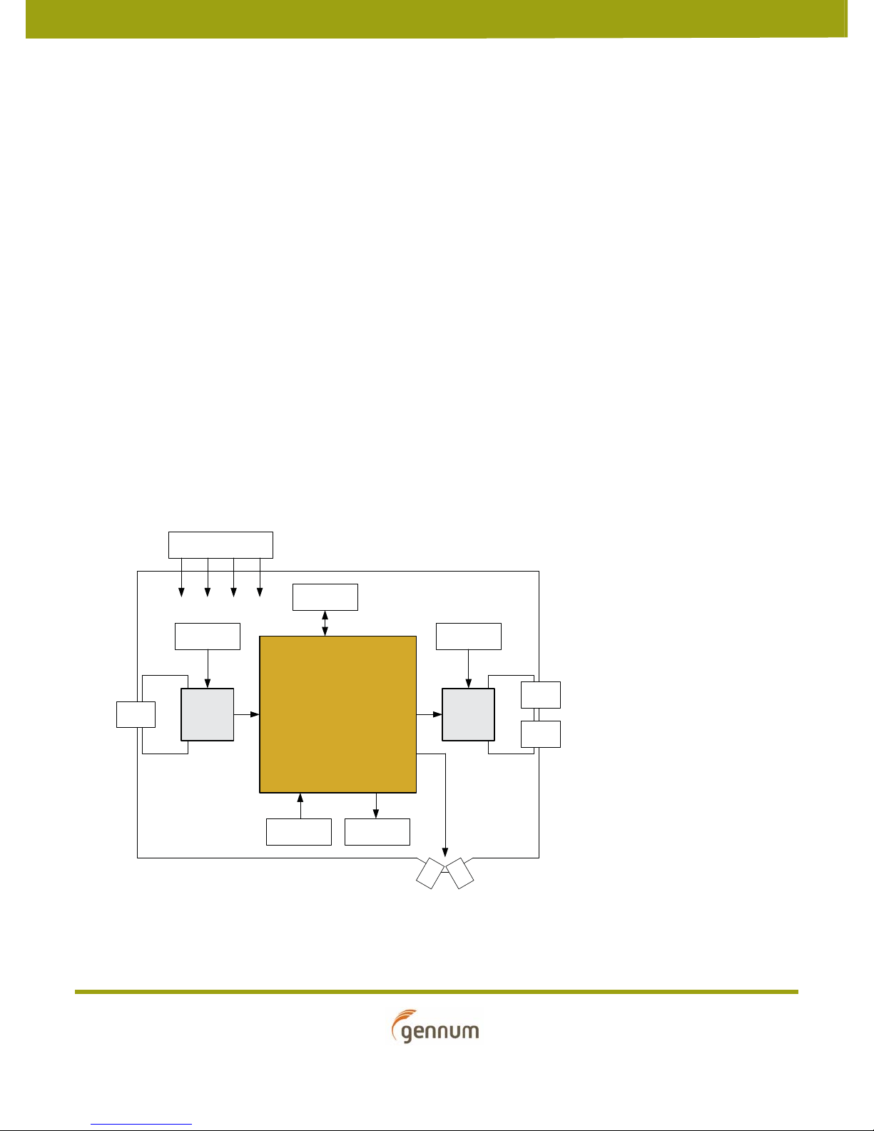
Overview ..............................................................................................................................................................4
1. Evaluation Board User Guide ....................................................................................................................5
1.1 SDI Inputs and Outputs ..................................................................................................................6
1.2 DDO1/RCO Output ..........................................................................................................................6
1.3 SPI Interface .......................................................................................................................................6
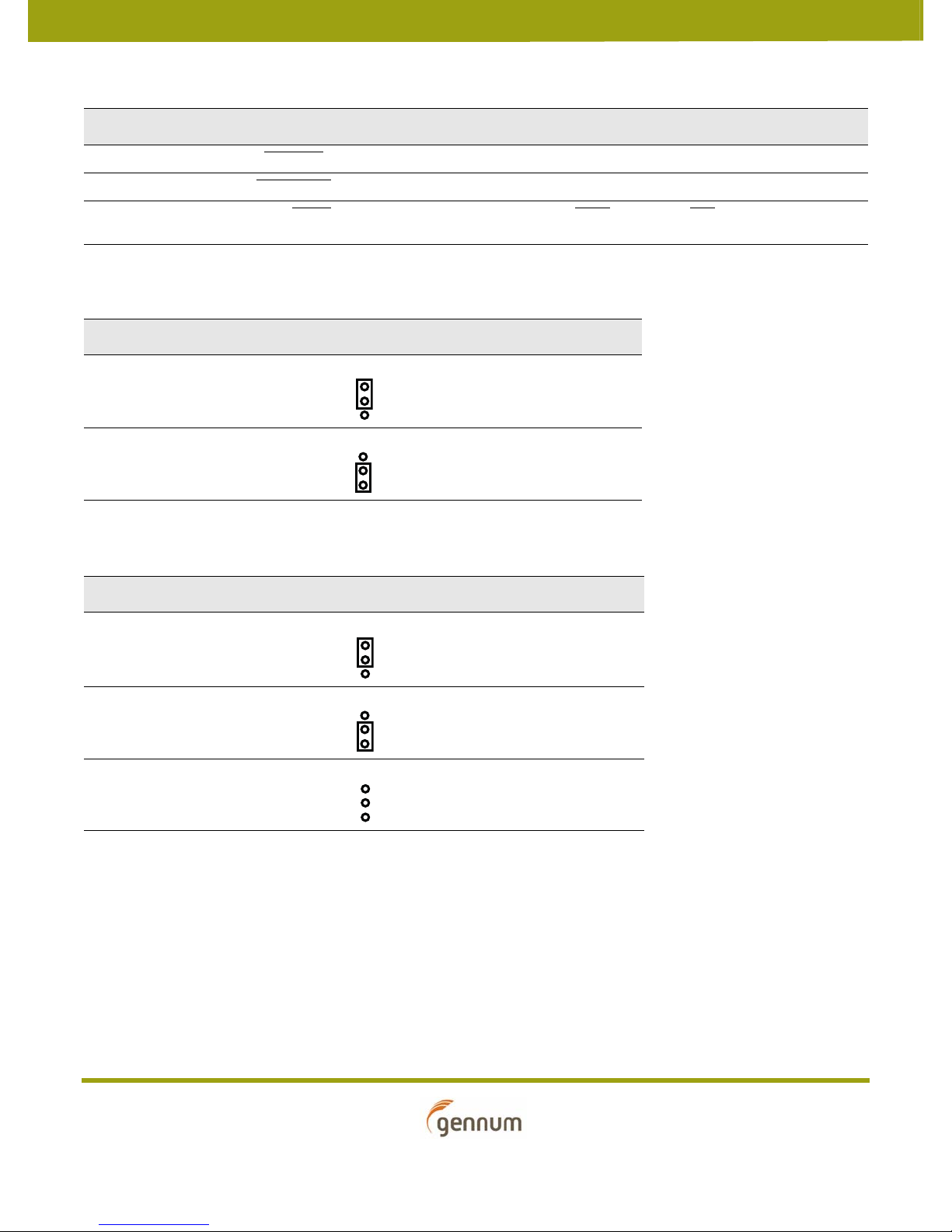
1.4 GS2985 RCLK Control I/O ..............................................................................................................6
1.5 GS2984 EQ Control I/O ...................................................................................................................7
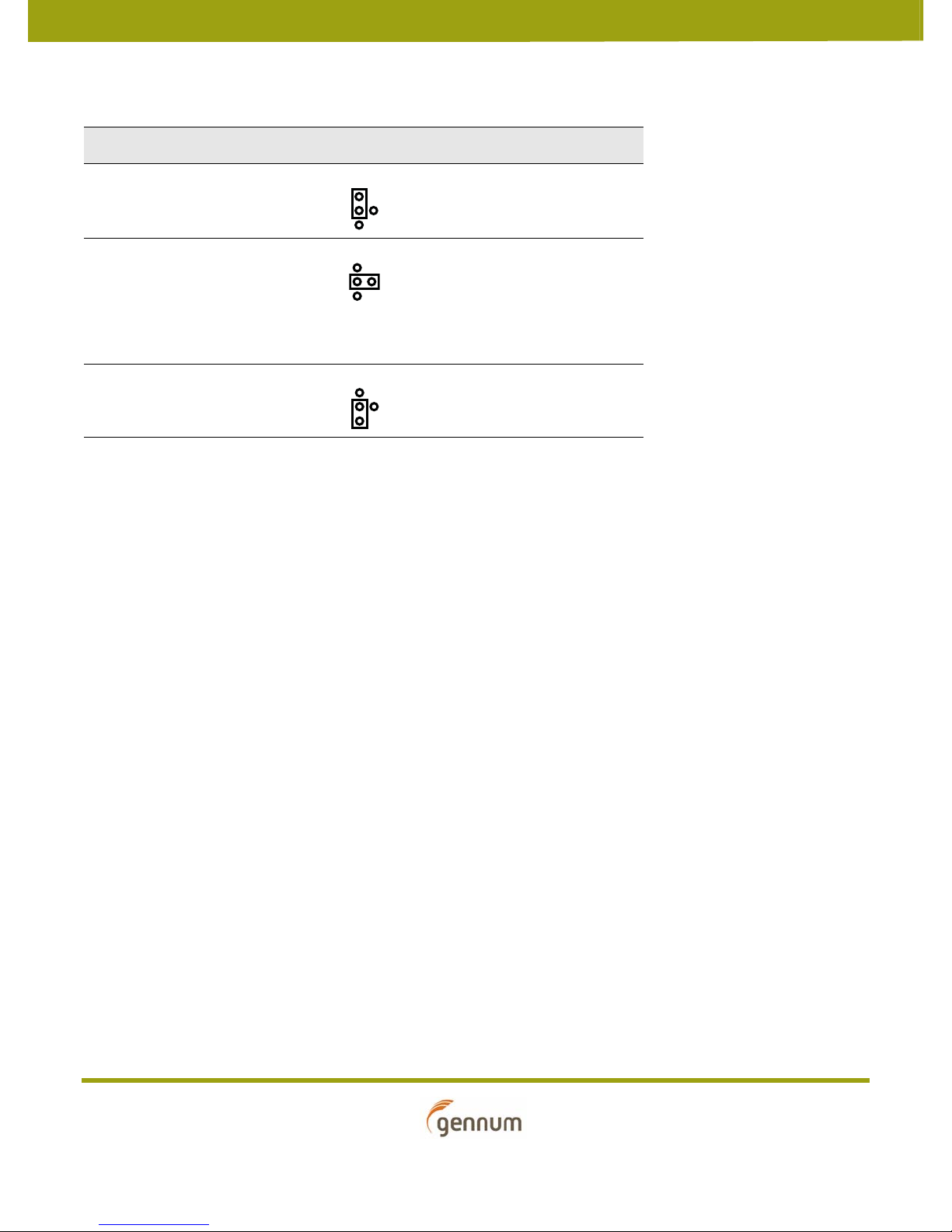
1.6 GS2988 CD Control I/O ..................................................................................................................8
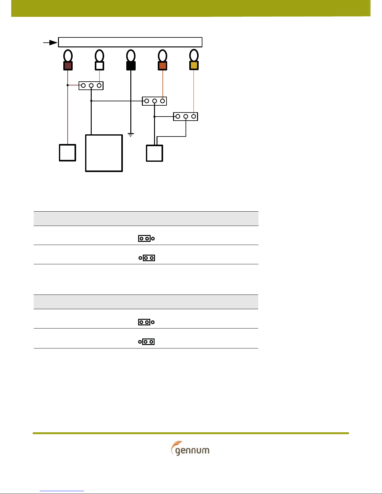
1.7 Power Pins ...........................................................................................................................................9
1.8 Measuring ORL ............................................................................................................................... 11
1.9 Board & Software Setup Instructions ...................................................................................... 11
1.9.1 Installing the Gennum USB Dongle Board Software ............................................. 11
1.9.2 Installing the GS2985 Control Software..................................................................... 13
1.9.3 Setting Up the Hardware ................................................................................................ 16
1.9.4 GS2985 Control Software ............................................................................................... 17
Functionality of Buttons ............................................................................................................................... 18
Functionality of Knobs .................................................................................................................................. 18
Pin Override Functionality .......................................................................................................................... 19
1.9.5 Start-up Process ................................................................................................................. 19
1.10 Optional Connectors .................................................................................................................. 19
2. Schematics .................................................................................................................................................... 20
2.1 EB-GS2985-S Schematic .............................................................................................................. 20
2.2 Power & Control Schematic ....................................................................................................... 21
3. Board Layout................................................................................................................................................ 22
4. Bill of Materials............................................................................................................................................ 23
Version ECR Date Changes and / or Modifications
2 152337 July 2009 Updates to Sections 1.9.4 GS2985 Control
Software, 2. Schematics and 4. Bill of
Materials. Added Section Pin Override
Functionality.
1 152007 June 2009 Changed inductor value in Section 2.1
EB-GS2985-S Schematic and Section 4. Bill of
Materials. Modified Section 1.8 Measuring
ORL.
0 151624 May 2009 New document.

EB-GS2985-S
Evaluation Board User Guide
52246 - 2 July 2009
3 of 25
General Description
The GS2985-S evaluation package is designed to accelerate the evaluation process of the
GS2985 Multi-rate SDI Reclocker with Equalization and De-emphasis.
It is strongly recommended to read the GS2985 Data Sheet (Doc ID: 36663_DocX.pdf)
before using this evaluation kit.
Evaluation Kit Contents
• Gennum EB-GS2985-S Evaluation Board
• Gennum USB Dongle with Ribbon Cable
• CD containing GS2985 Evaluation Software, Drivers and Collateral

EB-GS2985-S
Evaluation Board User Guide
52246 - 2 July 2009
4 of 25
Overview
Together with the EB-GS2985-S (single-channel) Evaluation Board, this document
serves as a guide for evaluating the GS2985, a Gennum 3Gb/s, HD, SD SDI serial digital
reclocker. This document contains four main sections:
1. Evaluation Board User Guide.
2. Evaluation Board Schematics.
3. Evaluation Board Layout.
4. Evaluation Board Bill of Materials
The figure below shows a block diagram of the features and the functions of the
EB-GS2985-S.
The purpose of the EB-GS2985-S single-channel evaluation board is to evaluate the
GS2985 3G Video Reclocker (RCLK). It also features the GS2984 3G Equalizer (EQ) and
the GS2988 3G Cable Driver (CD). The GS2985 is designed to automatically recover the
embedded clock from a SMPTE-424M, SMPTE 292M, or SMPTE 259-C compliant digital
video signal, and re-time the incoming video data.
The GS2984 and the GS2988 are high-speed BiCMOS integrated circuits. The GS2984 is
designed to equalize and restore signals received over 75Ω coaxial cable, and the
GS2988 is designed to drive one to two 75Ω coaxial cables.
The EB-GS2985-S also provides access to the GS2985’s internal registers via SPI. A
Gennum SPI dongle is included in the kit, to communicate with the GS2985 through a
USB connection.
Block Diagram of the EB-GS2985-S
GS2984 GS2988
GS2985
SMA
OptimizedIR L OptimizedORL
DDO0
DDO1/RCO
DDI0
SPIInterface
BNC
BNC
BNC
RCLK CTRL
SMA
LE Ds
EQ CTRL CD CTRL
Power Supplies
EQ RCLK CDCD_TERM

EB-GS2985-S
Evaluation Board User Guide
52246 - 2 July 2009
5 of 25
1. Evaluation Board User Guide
Figure 1-1 shows the inputs, outputs and power connections for the EB-GS2985-S.
Figure 1-1: GS2985 Single-channel Evaluation Board (EB-GS2985-S)
GND
SDO SDO
SDI
DATA1/RCLK Output
EQ Control
(SW3)
RCLK Control
(SW1)
KBB Input Select
(KBB_SEL)
RSET Resistor Select
(RSET_SEL)
EQ
RCLK
CD_TERM
CD
Power
Supply
Connections
CD Control
(SW2)
SPI Interface
MUTE SelectVCO Frequency Select
(VCO_SEL)
RCLK_SEL
CD_SEL
CD_TERM_SEL
LEDs
ORL_JP

EB-GS2985-S
Evaluation Board User Guide
52246 - 2 July 2009
6 of 25
1.1 SDI Inputs and Outputs
EB-GS2985-S features a single ended 75Ωinput through a BNC connector (SDI) and two
single ended 75Ωoutputs through two BNC connectors (SDO, SDO).
1.2 DDO1/RCO Output
The EB-GS2985-S features two SMA connectors (DDO1/RCO, DDO1/RCO) for the
recovered clock RCO and RCO or the data DDO1 and DDO1. This can be selected using
the position on SW1 marked DATA/CLOCK.
1.3 SPI Interface
The EB-GS2985-S features an SPI interface (JP1) which is used to access all of the GS2985
registers. The SPI interface is automatically enabled when the Gennum USB dongle is
connected. The Gennum USB Dongle can connect the EB-GS2985-S to a computer via
USB. When the ribbon cable on JP1 is removed, the SPI interface is automatically
disabled and the board goes into legacy mode. The GS2985 registers will maintain their
settings until the board is powered-down, or reset via the SPI interface. Table 1-1
describes the two modes of operation.
1.4 GS2985 RCLK Control I/O
There are a variety of components on the EB-GS2985-S board to facilitate manual
control of the GS2985 device. These are described in the tables below.
Table 1-1: SPI Interface Modes of Operation
Mode Setting
Legacy Mode HIF = 1
SPI Mode HIF = 0
Table 1-2: SW1 Positions
Switch Position Label Description HIGH (1) LOW (0) Default
1 BYPASS Bypass Bypass On Bypass Off 0
2 AUTOBYPASS Autobypass Autobypass On Autobypass Off 1
3AUTO/MAN
Auto/Manual Automatically locks
to incoming data
rate
Manual data rate
select
1
4 SS0 Data rate select [0] SS[1:0]
0 - Reserved
1 - 270 (Mb/s)
2 - 1485 or 1485/1.001 (Mb/s)
3 - 2970 or 2970/1.001 (Mb/s)
0
5 SS1 Data rate select [1] 0

EB-GS2985-S
Evaluation Board User Guide
52246 - 2 July 2009
7 of 25
1.5 GS2984 EQ Control I/O
A switch (SW3) and a jumper (MUTE_SEL) facilitate the manual configuration of the
GS2984 Equalizer on the EB-GS2985-S evaluation board. These are described in the
tables below.
6 DDO1_DIS DDO1 Disable DDO1 Mute Off DDO1 Mute On 1
7DATA_MUTE
Data Mute Data Mute Off Data Mute On 1
8DATA/CLOCK
Data/Clock select DDO1/DDO1
selected
RCO/RCO selected 1
Table 1-2: SW1 Positions
Switch Position Label Description HIGH (1) LOW (0) Default
Table 1-3: VCO Frequency Select (VCO_SEL)
Position Connection Description
3V3 (default) Sets correct VCO voltage for
a 3.3V power supply
2V5 Sets correct VCO voltage for
a 2.5V power supply
Table 1-4: KBB Input Select (KBB_SEL)
Position Connection Description
HI KBB = VCC
LOW KBB = GND
Not connected (default) KBB = unconnected

EB-GS2985-S
Evaluation Board User Guide
52246 - 2 July 2009
8 of 25
1.6 GS2988 CD Control I/O
A switch (SW2) and a jumper (RSET_SEL) facilitate the manual configuration of the
GS2988 Cable Driver on the EB-GS2985-S evaluation board. These are described in the
tables below.
Table 1-5: SW3 Positions
Switch Position Label Description HIGH (1) LOW (0) Default
1 GS Gain Select Compensation for
6dB flat attenuation
No change in gain 0
2 BP Bypass Bypass On Bypass Off 0
3 CM Common Mode Set
NOTE: CM should be
set to 1 when using
a 2.5V supply for the
Reclocker.
Output CM set to
2.1V
Output CM set to
2.9V
0
Table 1-6: MUTE Select (MUTE_SEL)
Label Connection Description
AUTO (default) Auto Mute
HI Mute On
LO Mute Off
Table 1-7: SW2 Positions
Switch Position Label Description HIGH (1) LOW (0) Default
1EQInput trace
equalization
Input trace
equalization Off
Input trace
equalization On
1
2DIS
Output disable Output 1 enabled Output 1 disabled 1

EB-GS2985-S
Evaluation Board User Guide
52246 - 2 July 2009
9 of 25
1.7 Power Pins
The default supply configuration allows for quick power-up of the EB-GS2985-S by
applying 3.3V to the EQ post and grounding the GND post. Power supply connections
can be changed to evaluate each device seperately over their specified range of supply
voltages.
The GS2984 EQ accepts a 3.3V power supply, while the GS2985 RCLK and GS2988 CD
accept either 3.3V or 2.5V. Furthermore, the termination voltage (CD_TERM) on the
GS2988 CD accepts up to 5V when a high output swing is desired.
Please refer to Figure 1-2. The EB-GS2985-S evaluation board uses an external power
supply through a power post labelled “EQ” to power the EQ at 3.3V. Optionally, a second
power supply can be connected to the post labelled “RCLK” to power the GS2985 and a
third power supply can be connected to the post labelled “CD” to power-up the GS2988
device. Alternatively, the “RCLK” supply can track the “EQ” supply by properly
configuring the RCLK_SEL jumper. Similarly, the “CD” supply can track the “RCLK”
supply by properly configuring the CD_SEL jumper. By default, the jumpers are
configured so that all three devices are powered off the same supply connected to the
“EQ” post. The power supply configuration jumpers are described in Table 1-9,
Table 1-10 and Table 1-11.
NOTE: The cable driver power supply (CD) cannot have a higher potential than the
reclocker power supply (RCLK).
Table 1-8: RSET Resistor Select (RSET_SEL)
Label Connection Description
R19 (default) 800mV output swing
R20 1.8V output swing
NOTE: The CD_TERM post
should be connected to 5V,
and the CD_TERM_SEL
jumper should be set to EXT
in order to achieve this
output swing.
R21 500mV output swing

EB-GS2985-S
Evaluation Board User Guide
52246 - 2 July 2009
10 of 25
Figure 1-2: Power Supply Connections
Table 1-9: Reclocker Supply Select (RCLK_SEL)
Position Connection Description
EQ (default) Reclocker supply tracks
Equalizer supply
EXT Reclocker uses a separate
power supply (RCLK post)
Table 1-10: Cable Driver Supply Select (CD_SEL)
Position Connection Description
RCLK (default) Cable Driver supply tracks
Reclocker supply
EXT Cable Driver uses a separate
power supply (CD post)
3V3
RCLK_VCC
CD_VCC
EQ_VCC
GND
3V3 GND 3V3
MAX
EQ RCLK GND CD
5V
CD_TERM
TE RM_VCC
CD_SEL
CD
RCLK
RCLK _SEL
CD_TERM_SEL
EQ

EB-GS2985-S
Evaluation Board User Guide
52246 - 2 July 2009
11 of 25
1.8 Measuring ORL
To measure Output Return Loss (ORL) on the EB-GS2985-S board, follow the next steps:
1. Disconnect ORL_JP
2. Set the SW2 position marked EQ to LOW “0”. This sets the EQ input of the cable
driver to LOW “0”.
3. The cable driver outputs are now balanced.
ORL can now be measured single-endedly using a Network Analyzer.
Please refer to the GS2988 data sheet for more information regarding balance mode.
1.9 Board & Software Setup Instructions
1.9.1 Installing the Gennum USB Dongle Board Software
Connect the Gennum USB Dongle Board to a Computer.
Insert one end of the USB cable to the computer USB port, and the other end to the
Gennum USB Dongle Board. The microcontroller will come pre-programmed with
firmware.
Install the USB Device Driver (if required):
1. Insert CD.
2. Double-click on the
MCHPFSUSB_Setup.exe
icon on the CD-ROM and proceed
with installation.
3. For Windows XP users, follow instructions below.
Table 1-11: Cable Driver Termination Supply (CD_TERM_SEL)
Position Connection Description
CD (default) Termination voltage supply
tracks Cable Driver supply
EXT Termination voltage uses
separate power supply
(CD_TERM post)
Table 1-12: ORL Jumper Settings (ORL_JP)
Connection Description
Normal Operation (Default)
ORL Measurement

EB-GS2985-S
Evaluation Board User Guide
52246 - 2 July 2009
12 of 25
4. Click Install from a list or specific location (Advanced).
Figure 1-3: Install window for the Gennum USB Dongle Board
5. Select
Include this location…
and navigate (browse) to the directory
D:\MCHPFSUSB\PC\MCHPUSB Driver\Release and click Open. De-Select
Search removable media…
Figure 1-4: Select the location of the files
6. The final dialogue will indicate that the driver has been successfully installed. Click
Finish. It is not required to restart the system.

EB-GS2985-S
Evaluation Board User Guide
52246 - 2 July 2009
13 of 25
Figure 1-5: Completed installation of the Gennum USB Dongle Board
1.9.2 Installing the GS2985 Control Software
Install the GS2985 Control Software (one time installation per computer):
1. Insert the Gennum GS2985 Evaluation Board CD.
2. Traverse to the GS2985_GUI folder.
3. Click setup.exe and follow instructions to install.
The GS2985 Control Installation Wizard will begin.

EB-GS2985-S
Evaluation Board User Guide
52246 - 2 July 2009
14 of 25
Figure 1-6: GS2985 Control Welcome Screen
You will be prompted to select a directory location to install the GS2985 software.
Figure 1-7: GS2985 Control File Location Window

EB-GS2985-S
Evaluation Board User Guide
52246 - 2 July 2009
15 of 25
The next screen is to verify your choices.
Figure 1-8: GS2985 Control Ready to Begin Installation Window
The window below will appear once the wizard finished the installation.
Figure 1-9: GS2985 Control Successful Completion Window

EB-GS2985-S
Evaluation Board User Guide
52246 - 2 July 2009
16 of 25
1.9.3 Setting Up the Hardware
Figure 1-10: Gennum USB Dongle Board
When the Gennum USB Dongle is configured properly, the LEDs D6 and D7 will blink
alternately.
The Master Reset Button is pushed to reset the Gennum USB Dongle Board, in case the
LEDs D6 and D7 stop blinking.
Connect the EB-GS2985-S Board to the USB Dongle Board as per Figure 1-11.
Figure 1-11: EB-GS2985-S Board + USB Dongle Board setup
When the Gennum USB Dongle Board is connected to the EB-GS2985-S, the GS2985
automatically switches from Legacy mode to SPI mode. As an indicator, the HIF LED on
the EB-GS2985-S board turns off.
Pin #1 Reset Button
USB Connector
LED 1
LED 2
LED 4
LED 5
LED 3
LED 6
LED 7
Ribbon Cable
Connector to
GS2985-SEvaluation
Board
Gennum USB
Dongle Board
USB Connector
to PC
Note: The ribbon cable can have the red line on either side.
To get a proper working system, keep the boards in the
present lay-out and DO NOT twist the ribbon cable
when attaching.
Ribbon
Cable
EB-GS2985-S
Evaluation Board

EB-GS2985-S
Evaluation Board User Guide
52246 - 2 July 2009
17 of 25
1.9.4 GS2985 Control Software
1. Start GS2985 Control Software by clicking on the appropriate link on the Start
Menu.
2. Control SPI Register Settings & Observe Outputs.
Figure 1-12: Gennum GS2985 Control Interface

EB-GS2985-S
Evaluation Board User Guide
52246 - 2 July 2009
18 of 25
Functionality of Buttons
Functionality of Knobs
Offset Correction Equalizer offset correction enable
Attenuation Input attenuation enable. Should be enabled
for input signals above 1Vpp differential
Polarity Invert Data polarity invert
Crystal Buffer Crystal buffer disable
Power Down Chip powers down when asserted
LOS Auto Mute When enabled the output will automatically
mute if Loss of Signal is HIGH
Read Read DATA from a GS2985 register (x00 -
x0D)
Write Write DATA to a GS2985 register (x00 - x0D)
ReadStatus Reads status of outputs SS0, SS1, LOS, SD/HD,
Locked
• SS1 and SS0 indicate the selected data
rate (00 - Reserved, 01 - 270Mbs, 10 -
1485Mbs, 11 - 2970Mbs)
• LOS indicates when a Loss of Signal
occurs
• SD/HD indicates when SD mode is
selected
• LOCKED indicates when the PLL is
locked
Reset IC Resets the GS2985
EQ Gain Equalizer gain setting
DE Setting De-emphasis boost amplitude control (0 =
lowest setting, 7 = highest setting)
Output Swing Sets the output amplitude (400mV
swing/800mV swing)
LOS Detection Method Legacy = edge detection method, New =
signal strength detection method, Dual =
combination of edge detection and signal
strength
LOS Threshold Sensitivity LOS Threshold Adjust. 0 = least sensitive,
3 = most sensitive

EB-GS2985-S
Evaluation Board User Guide
52246 - 2 July 2009
19 of 25
Pin Override Functionality
1.9.5 Start-up Process
1. Ensure the software and drivers are installed on your PC.
2. Connect the Gennum USB Dongle Board to the EB-GS2985-S using the supplied
ribbon cable as per Figure 1-11.
3. Connect the power supplies as per Section 1.7 and power up the board.
4. Connect the Gennum USB Dongle Board to a PC USB port via a USB cable.
5. Perform a hard reset, via the Reset button on the Gennum USB Dongle board as per
Figure 1-10.
6. Launch the GS2985 Control Software on the PC connected to the Gennum USB
Dongle Board.
7. The GS2985 registers can now be controlled through the SPI.
1.10 Optional Connectors
The EB-GS2985-S board also features footprints for two optional test points (SQ_ADJ
and XTAL_BUF_OUT).
DATA/CLOCK Sets the DDO1 output.
checked = DATA, unchecked = CLOCK
DDO1 DISABLE Disables DDO1
DATA_MUTE Mutes all DATA outputs
AUTOBYPASS Sets the reclocker in autobypass mode
BYPASS Sets the reclocker in bypass mode
MANUAL checked = manual data rate selection,
unchecked = auto data rate detection
KBB Sets KBB to one of three settings (GND,
Floating, VCC)

EB-GS2985-S
Evaluation Board User Guide
52246 - 2 July 2009
20 of 25
2. Schematics
2.1 EB-GS2985-S Schematic
Figure 2-1: EB-GS2985-S Schematic
C7
10n
controlled75R
SPI_MISO
GND
J5
SMA
GNDGND
GND
DDI0
1
HIF
2
DDI0
3
GND
4
DDI1
5
6
DDI1
7
GND
8
DDI2
9
10
DDI2
11
GND
12
DDI3
13
14
DDI3
15
GND
16
DDI_SEL0
17
DDI_SEL1
18
BYPASS
19
AUTOBYPASS
20
AUTO/MAN
21
VCC_VCO
22
VEE_VCO
23
24
SS0
25
SS1
26
VDD_1P8
27
LOCKED
28
LOS
29
VDD_DIG
30
VSS_DIG
31
GND
32
VEE_DDO0 48
VCC_DDO0 47
DDO0 46
DE0_EN 45
DDO0 44
GND_DRV 43
VEE_DDO1 42
VCC_DDO1 41
DDO1/RCO40
DE1_EN 39
DDO1/RCO38
DATA/CLOCK37
DATA_MUTE 36
DDO1_DISABLE 35
KBB 34
SD/HD 33
64
CP_CAP 63
LF+ 62
VCC_CP61
VEE_CP60
N/C59
SDI/EQ0_EN 58
SDO/EQ1_EN 57
SCK/EQ2_EN 56
CS/EQ3_EN 55
54
XTAL- 53
XTAL+ 52
XTAL_BUF_OUT 51
50
GND 49
TAB
U2
GS2985
R211k21R
BYPASS
1
3
2
4
JP4
VCC3
VCC2
1
3
2
JP6
GND
R20332R
AUTOBYPASS
C1110n
GND
VCC2
R60
0R
GND
R4
49k9
VCC2
R52 1k
VCC1
VCC2
R19825R
C13 10n
C20 10n
Y1
CS10-27.000MABJ
VCC2
C3
47n
EQ_CMSET
6
15
13
2
1211
9
14
7 8
5
43
16
1
10
JP1
87831-1620
GND
R51 1k
C1
18p
R54 1k
GND
controlled75R
controlled75R 1 7
J3BNC
VCC_Term
GND
R15 75R
R16
75R
C22
10n
L3 3n9
GND
C18
4u7
R2
49k9
C2
18p
VCC2
C91u
HIF = LOW, SPI MODE
R14 DNP
R1
49k9
R55
DNP
HIF = HIGH, LEGACY MODE
R56
DNP
GND
GND
CD EQ_EN
R5
221R
SPI_SCK
JP14
LOCKED
controlled100R
SPI_SS0
SDI
2
VEE_A
1VEE_D 12
VCC_A 16
SDI
3
GAIN_SEL
4
BYPASS
7
SQ_ADJ
8
CMSET 9
SDO 10
SDO 11
CD15
MUTE 14
VCC_D 13
AGC
5
AGC
6
TAB
U1
GS2984
L1 6n2
GND
R7 75R
C5
10n
R12
75R
C14 1u
R13
37R4
VCC1 VCC1
C6
10n
GND GND
differential
C10 1u
GND
C21
470n
C19
470n
C34
220n
GND
GND
1
7
J1BNC
VCC2
C30 10n
LOS
CD_DISb
GND
C28
4u7
HIF
VCC2
GND
R23
422R
C31 1u
R3
49k9
controlled100R
C4
220n
GND
controlled100R
place GND via next
to test point
differential
differential
VCC2
16pin SPI Header (2mm)
C29
4u7
R24
267R
1
3
2
JP5
SS0
GND
C33
10u
R9 49k9
1
3
2
4
JP2
C23 DNP
SS1
DDI
1
DDI
2
VCC 9
EQ_EN 16
VEE
3
NC
8
SDO 12
SDO 11
NC13
NC
5
RSET
4
DISABLE
6
RSVD
7OSP14
SD/HD 10
NC15
TAB
U3
GS2988
C27 DNP
R18 DNP
C15 DNP
GND
GND
VCC_Term
GNDGND
VCC3
C32
10n
VCC2
GND
R8
75R
R10 75R
C2610n
L2 3n9
J4
SMA
C8
10n
C16DNP
C12
4u7
17
J2BNC
GND
1
JP3
TP DN P
EQ_GAIN_SEL
C42
DNP
VCC2
C25 10n
VCC2
C43
DNP
GND
GND
EQ_BYPASS
GND
GND
VCC2
GND
GND
GND
R53 1k
GND
GND
SPI_MOSI
C24 10n
R61M
GND
EQ_SQ_ADJ
SD/HD
N/C
N/C
N/C
N/C
N/C
N/C
N/C
SD/HD
DATA_MUTE
DATA/CLOCK
DDO1_DISABLE
AUTO/MAN
HIF
Table of contents
Other GENNUM Motherboard manuals