10
Revision 2.1
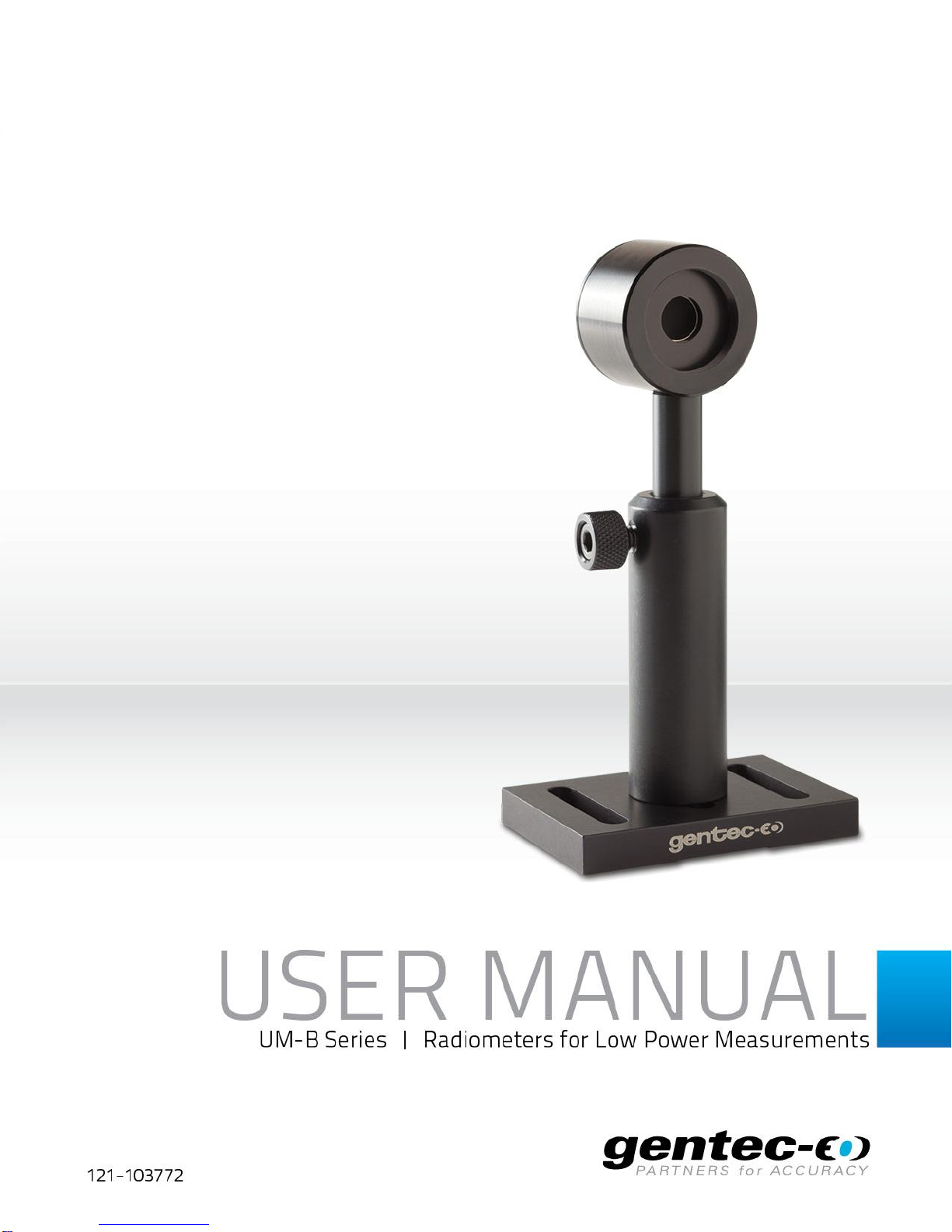
UM-B Series Instruction Manual Gentec Electro-Optics Inc. All rights reserved
NOTE: The parameters programmed in the DB-15 “Smart Interface” are for a 1 Mload
impedance.
3- Remove the detector's protective cover, when applicable.
4- Put the optical chopper (SDC-500 or equivalent) into the laser beam path and adjust the
frequency at 10Hz (laser beam must be contained within the aperture).
5- Put the wattmeter head into the laser beam path after the chopper (laser beam must be
contained within the aperture).
CAUTION: Be careful not to exceed the maximum levels and densities in: energy, peak
power and average power as stated in the specifications pages.
NOTE: As with all pyroelectric devices, these detectors have some position and beam size
linearity. For the most accurate measurements, the beam should normally be
centered on the sensor surface and the beam diameter should ideally be close to
that of the original calibration conditions, which is 100% encircled power (of a semi-
Gaussian beam stopped at 1/e2) applied to a diameter equal to 80% of the
detector aperture. The use of a divergent lens, a Lambertian diffuser such as opal
glass, or any other method of beam spreading, is recommended for this purpose.
Please take note that all of the laser light must be directed within the detector
aperture and that the transmission loss through the optical component must be
known.
3.2 Working at other wavelengths than 1.064µm
The monitor will automatically configure himself using the data stored in the EEPROM of
the DB-15 “Smart Interface”. This includes the calibration sensitivity and wavelength
corrections for 20 current wavelengths34.
For more precise measurements with a UM-B Series wattmeter at wavelengths other than
those already corrected by the “Personal wavelength correctionTM’’
data programmed into
the “Smart Interface”, a correction factor
is automatically set in the monitor to compensate
for the change in sensitivity of the wattmeter caused by the change in absorption of the
optical absorber at different wavelengths. This automatic correction is a linear interpolation
between two measured values of the ‘’Personal wavelength correction’’.
Refer to the spectral curve of the “ Personal Wavelength Correction TM “ certificate supplied with the
wattmeter
Refer to the monitor manuals for instructions.