Gentec-E Maestro User manual


MAESTRO User’s Manual Revision 8.0 1
WARRANTY
The Gentec-EO MAESTRO Single Channel Laser Power, Energy and Power/Energy Meter carries a one-
year warranty (from date of shipment) against material and/or workmanship defects, when used under
normal operating conditions. The warranty does not cover damages related to battery leakage or misuse.
Gentec-EO Inc. will repair or replace, at Gentec-EO Inc.’s option, any MAESTRO that proves to be
defective during the warranty period, except in the case of product misuse.
Any attempt by an unauthorized person to alter or repair the product voids the warranty.
The manufacturer is not liable for consequential damages of any kind.
Customers must fill in and mail the warranty card in order to activate the warranty.
In case of malfunction, contact your local Gentec-EO distributor or nearest Gentec-EO Inc. office to obtain
a return authorization number. The material should be returned to:
Gentec Electro-Optics, Inc.
445, St-Jean-Baptiste, Suite 160
Québec, QC
Canada G2E 5N7
Tel: (418) 651-8003
Fax: (418) 651-1174
e-mail: service@gentec-eo.com
Website: www.gentec-eo.com
CLAIMS
To obtain warranty service, contact your nearest Gentec-EO agent or send the product, with a description
of the problem, and prepaid transportation and insurance, to the nearest Gentec-EO agent. Gentec-EO
Inc. assumes no risk for damage during transit. Gentec-EO Inc. will, at its option, repair or replace the
defective product free of charge or refund your purchase price. However, if Gentec-EO Inc. determines
that the failure is caused by misuse, alterations, accident or abnormal conditions of operation or handling,
you will be billed for the repair and the repaired product will be returned to you, transportation prepaid.

MAESTRO User’s Manual Revision 8.0 2
SAFETY INFORMATION
Do not use the MAESTRO if the device or the detector looks damaged, or if you suspect that the
MAESTRO is not operating properly.
Appropriate installation must be done for water-cooled and fan-cooled detectors. Refer to the specific
instructions for more information. Wait a few minutes before handling the detectors after power is
applied. Surfaces of the detectors get very hot and there is a risk of injury if they are not allowed to cool
down.
Note: This equipment has been tested and found to comply with the limits for a Class B digital
device, pursuant to part 15 of the FCC Rules. These limits are designed to provide
reasonable protection against harmful interference in a residential installation. This
equipment generates, uses, and can radiate radio frequency energy. If not installed
and used in accordance with the instructions, it may cause harmful interference to radio
communications. However, there is no guarantee that interference will not occur in a
particular installation. If this equipment does cause harmful interference to radio or
television reception, which can be determined by turning the equipment off and on, try
to correct the interference by taking one or more of the following steps:
•Reorient or relocate the receiving antenna.
•Increase the distance between the equipment and receiver.
•Connect the equipment to an outlet that is on a different circuit than the receiver.
•Consult the dealer or an experienced radio/TV technician for help.
Caution: Changes or modifications not expressly approved in writing by Gentec-EO Inc. may
void the user’s authority to operate this equipment.
SYMBOLS
The following international symbols are used in this manual:
Refer to the manual for specific Warning or Caution information to avoid any
damage to the product.
DC, Direct Current

MAESTRO User’s Manual Revision 8.0 3
TABLE OF CONTENTS
1THE MAESTRO SINGLE CHANNEL LASER POWER/ENERGY METER...........................................6
1.1 INTRODUCTION..................................................................................................................................6
1.2 SPECIFICATIONS ...............................................................................................................................7
1.3 FRONT PANEL DESCRIPTION..............................................................................................................9
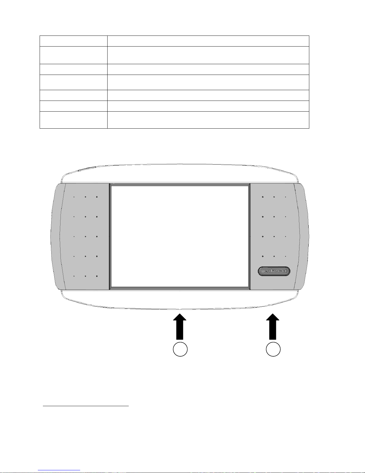
1.4 TOP PANEL DESCRIPTION................................................................................................................10
2GETTING STARTED...........................................................................................................................13
2.1 HOW TO ACCESS THE DIFFERENT MENUS OF THE MAESTRO’S USER INTERFACE...............................14
2.2 QUICK POWER AND ENERGY MEASUREMENT PROCEDURE..................................................................16
2.3 DESCRIPTION OF THE MAESTRO NAVIGATION MENU .......................................................................19
2.4 HOME.............................................................................................................................................20
2.4.1 Set Device.............................................................................................................................20
2.4.1.1 Date & Time (Not available on this version, check our web site for new versions)...........................21
2.4.1.2 Number of Digits...............................................................................................................................21
2.4.1.3 Serial Commands.............................................................................................................................22
2.4.1.4 Ethernet............................................................................................................................................23
2.4.1.5 Languages........................................................................................................................................24
2.4.2 Set Measure..........................................................................................................................25
2.4.2.1 Wavelength ......................................................................................................................................26
2.4.2.2 Range...............................................................................................................................................28
2.4.2.3 Measure Mode .................................................................................................................................29
2.4.2.4 Corrections.......................................................................................................................................32
2.4.2.5 Trigger Level ....................................................................................................................................33
2.4.3 Display...................................................................................................................................34
2.4.3.1 Display Parameters menu bar..........................................................................................................35
2.4.3.2 Real time display..............................................................................................................................38
2.4.3.3 Scope display...................................................................................................................................38
2.4.3.4 Needle display..................................................................................................................................40
2.4.3.5 Averaging display.............................................................................................................................40
2.4.3.6 Statistics display...............................................................................................................................42
2.4.4 Acquisition.............................................................................................................................45
2.4.5 Startup Config........................................................................................................................48
2.4.6 About.....................................................................................................................................49
2.5 SEARCH.......................................................................................................................................50
2.6 INFO .............................................................................................................................................51
2.7 MANAGE USB..............................................................................................................................52
2.8 BACK TO MEASURE BUTTON....................................................................................................52
3SERIAL COMMUNICATION INTERFACE ..........................................................................................53
3.1 USB SERIAL COMMUNICATION ........................................................................................................53
3.1.1 Installation .............................................................................................................................53
3.1.1.1 Installation for Windows™:...............................................................................................................53
3.1.2 Setting up Communication to the MAESTRO .......................................................................53
3.1.2.1 Verify COM Port...............................................................................................................................53
3.1.2.2 Connect to the MAESTRO ...............................................................................................................53
3.1.2.3 To echo commands..........................................................................................................................54
3.1.2.4 Test the connection..........................................................................................................................54
3.1.2.5 HyperTerminal settings shortcut.......................................................................................................54
3.2 ETHERNET COMMUNICATION ...........................................................................................................55
3.3PC-MAESTRO USER-FRIENDLY SERIAL DATA ACQUISITION SOFTWARE.............................................56
3.4 TRADITIONAL COMMUNICATION SETTINGS........................................................................................57
3.4.1 Serial Command format ........................................................................................................57
3.4.1.1 Serial Protocol Rules:.......................................................................................................................57
3.4.1.2 Text mode rules:...............................................................................................................................57
3.4.2 MAESTRO Binary Mode Description ....................................................................................58
3.4.2.1 Description .......................................................................................................................................58

MAESTRO User’s Manual Revision 8.0 4
3.4.2.2 Codification.......................................................................................................................................58
3.4.3 Serial Command Directory ....................................................................................................59
3.4.3.1 Serial commands..............................................................................................................................61
3.4.3.2 Error Messages................................................................................................................................76
3.4.4 Legacy monitor serial commands..........................................................................................77
3.4.4.1 Emulated SOLO2 Serial commands.................................................................................................77
3.4.4.2 Error Messages for SOLO2 Serial mode..........................................................................................88
4MAINTENANCE...................................................................................................................................89
4.1 USB INSTALLATION FOR THE MAESTRO.........................................................................................89
4.2 FREE SOFTWARE UPGRADE ............................................................................................................89
4.3 BATTERY CHARGING.......................................................................................................................89
4.4 TROUBLESHOOTING ........................................................................................................................89
5DECLARATION OF CONFORMITY....................................................................................................90
6APPENDIX A .......................................................................................................................................91
6.1 QED/12/25/50/65/95.....................................................................................................................91
7APPENDIX B .......................................................................................................................................93
7.1 RECYCLING AND SEPARATION PROCEDURE.......................................................................................93
7.2 SEPARATION:..................................................................................................................................93
7.3 DISMANTLING PROCEDURE:.............................................................................................................93

MAESTRO User’s Manual Revision 8.0 5
LIST OF ILLUSTRATIONS
FIG.1-1 MAESTRO FRONT PANEL .................................................................................................................9
FIG.1-2 MAESTRO TOP PANEL ...................................................................................................................10
FIG.1-3 TYPICAL PULSE SHAPE OF A PYROELECTRIC DETECTOR......................................................................12
FIG.2-1 MAESTRO START UP WINDOW ........................................................................................................13
FIG.2-2 HIERARCHY OF THE MAESTRO’S USER INTERFACE STRUCTURE........................................................14
FIG.2-3 PARAMETERS MENU TO SET THE DETECTOR’S ZERO LEVEL .................................................................17
FIG.2-4 THE NAVIGATION MENU BAR ..............................................................................................................19
FIG.2-5 THE HOME MENU WINDOW...............................................................................................................20
FIG.2-6 THE SET DEVICE MENU WINDOW .......................................................................................................21
FIG.2-7 THE NUMBER OF DIGITS MENU WINDOW.............................................................................................22
FIG.2-8 SERIAL COMMANDS MENU WINDOW ...................................................................................................23
FIG.2-9 ETHERNET CONFIGURATION MENU WINDOW.......................................................................................24
FIG.2-10 LANGUAGE CONFIGURATION MENU WINDOW ....................................................................................25
FIG.2-11 THE SET MEASURE MENU WINDOW..................................................................................................26
FIG.2-12 THE WAVELENGTH MENU WINDOWS ................................................................................................27
FIG.2-13 POPUP WINDOW TO ENTER A USER DEFINED WAVELENGTH ...............................................................28
FIG.2-14 THE RANGE SELECTION MENU WINDOW ...........................................................................................29
FIG.2-15 THE MEASURE MODE SELECTION MENUWINDOW FOR A THERMOPILE DETECTOR HEAD.......................30
FIG.2-16 SETTING CORRECTION MENU..........................................................................................................32
FIG.2-17 TRIGGER LEVEL WINDOW................................................................................................................33
FIG.2-18 DISPLAY MENU WINDOW..................................................................................................................35
FIG.2-19 THE DISPLAY PARAMETERS MENU BAR............................................................................................35
FIG.2-20 REAL TIME DISPLAY ........................................................................................................................38
FIG.2-21 SCOPE TIME DISPLAY......................................................................................................................39
FIG.2-22 DIGITAL NEEDLE DISPLAY................................................................................................................40
FIG.2-23 AVERAGING DISPLAY.......................................................................................................................41
FIG.2-24 STATISTICS DISPLAY.......................................................................................................................42
FIG.2-25 STATISTICS SETTINGS POPUP WINDOW ............................................................................................43
FIG.2-26 STATISTICS DURATION SETTINGS POPUP WINDOW ............................................................................44
FIG.2-27 DATA SAMPLING PARAMETERS WINDOW MENU..................................................................................46
FIG.2-28 STARTUP CONFIG MENU WINDOW....................................................................................................48
FIG.2-29 ABOUT WINDOW. ............................................................................................................................49
FIG.2-30 SEARCH WINDOW...........................................................................................................................50
FIG.2-31 INFORMATION MENU WINDOW..........................................................................................................51
FIG.2-32 MANAGE USB MENU WINDOW.........................................................................................................52
FIG.3-1 MAESTRO ETHERNET COMMUNICATION EXAMPLE APPLICATION.......................................................56

MAESTRO User’s Manual Revision 8.0 6
1 THE MAESTRO SINGLE CHANNEL LASER POWER/ENERGY METER
1.1 Introduction
To obtain the full performance from the MAESTRO, we recommend that you read this manual carefully.
The MAESTRO is a microprocessor-based power and energy meter that uses the latest technology to
provide a multitude of options in a user-friendly environment. It is intuitively accessible using a touch
screen. It is a complete power and energy meter. The MAESTRO provides a statistical analysis of your
measurements. It allows you to store data on an external USB key. Moreover, the MAESTRO can be
updated by connecting a USB key with the new file available on our web site in the download section.
The MAESTRO has enhanced network capabilities that take further advantage of the USB port for data
acquisition and remote control. In addition to the external USB key, it can also transfer data files to a PC
for more sophisticated data analysis. Furthermore, the MAESTRO responds to commands through the
PC interface using the USB port. To transform your PC screen into a virtual MAESTRO, look for the
easy-to-use communications software on our website.
There is no need to enter the head specifications when connecting the new Gentec-EO power or energy
detector heads, for heads version 5 and above. The MAESTRO is already internally set to accept the
latest Gentec-EO wattmeter and joulemeter heads with a DB-15 connector. The MAESTRO supports
both fast and slow heads with a rise time from 5 s to 10 s.
The MAESTRO can reread heads in hot plug situation. Before inserting a new head, wait for the
MAESTRO to stop displaying numbers. Once the head has been detected, the monitor will wait 2
seconds to ensure that the head is properly inserted. If you do not respect these conditions and the head
is not read correctly, reboot the MAESTRO.
Unpacking
Each Gentec-EO MAESTRO is thoroughly tested and calibrated prior to shipment.
Visually inspect every MAESTRO unit after removing it from the shipping containers. If you see any
damage, retain all packaging materials and shipping receipts. Any damage claim should be made
promptly to the transportation company. Notify the nearest Gentec-EO representative concerning the
claim, so that any repair or replacement can be arranged as soon as possible.
Easy software upgrade
Keep in touch with the latest improvements to our user-friendly software by going to our website at
www.gentec-eo.com. Download the latest software version anytime and install it on the MAESTRO with
the USB key. You will find all the necessary information on downloading and upgrading in section 4.2.

MAESTRO User’s Manual Revision 8.0 7
1.2 Specifications
The following specifications are based on a one-year calibration cycle, an operating temperature of 18 to
28ºC (64 to 82ºF) and a relative humidity not exceeding 80%.
Table 1-1 List of Specifications
Power meter specifications
Power Range
4 pW to 30 kW
Power Scales
(photo diode head)
300pW, 1nW, 3nW, 10nW, 30nW, 100nW, 300nW, 1µW, 3µW, 10µW,
30µW, 100µW, 300µW, 1mW, 3mW, 10mW, 30mW, 100mW, 300mW,
1W, 3W
Power Scales
(thermal head)
16 scales: 300uW, 1mW, 3mW, 10mW, 30mW, 100mW, 300mW, 1W,
3W, 10W, 30W, 100W, 300W, 1kW, 3kW, 10kW, 30kW
Pyroelectric in power
mode range (UM-B)
100µW, 300µW, 1mW, 3mW, 10mW, 30mW, 100mW, 300mW
Resolution (digital)
Current scale/8192
Monitor Accuracy
±0.25 % 5 µV best scale1
Response Time
(accelerated)2
Head dependant (~1 sec)
Statistics
Current value, Max, Min, Average, Std Dev., RMS stability, PTP stability,
Time
Data Storage
Continuous on USB stick
Energy meter specifications
Energy Range
2fJ to 30kJ
Energy Scales [2]
(photo diode head)
300fJ, 1 pJ, 3 pJ, 10 pJ, 30 pJ, 300pJ, 1 nJ, 3 nJ, 10 nJ, 30 nJ, 100nJ,
300nJ, 1 uJ, 3 uJ,10uJ, 30uJ, 100µJ, 300µJ, 1mJ, 3mJ, 10mJ, 30mJ
Energy Scales [2]
(thermal head)
3mJ, 10mJ, 30mJ, 100mJ, 300mJ, 1J, 3J, 10J, 30J, 100J, 300J, 1kJ, 3kJ,
10kJ, 30kJ
Resolution (digital)
Current scale/8192
1
The 5µV offset can introduce an error into low power measurements with low sensitivity detectors. It is
essential to use the Zero Offset to rezero the Maestro before making a measurement in these conditions.
It is always good practice to use the Zero Offset. See section 2.2.
2
Varies with detector head.

MAESTRO User’s Manual Revision 8.0 8
Accuracy3
1.0 %50 µV < 6 kHz
2%50 µV 6kHz to 10 kHz
Default Trigger Level
2 %
SOFTWARE
TRIGGER LEVEL
0.1% to 99.9%, 0.1% resolution
Repetition
Frequency4
2 kHz for data acquisition in the real time full screen display, no missing
point
1.3 kHz for data acquisition in real time with time stamp, no missing point
2 kHz in statistics mode, no missing point
From 2 kHz to 10kHz the MAESTRO will send the latest energy pulse
every 500us. (corresponding to a subsampling at 2 kHz).
Frequency
Measurement
Accurate frequency measurement up to 14kHz
0-1000 Hz: 0.1% accuracy
1000-2000 Hz: 0.5%
2000-14000 Hz: 1%
Statistics
Current value, Max, Min, Average, Std Dev., RMS stability, PTP stability,
Time, Pulse #, Repetition Rate, Avg Power.
Data Storage
Continuous on USB stick
General Specifications
Digital Display
112.9 x 84.7mm RGB color LCD with touchscreen, 640 x 480 Pixels
Display Rate
3 Hz numeric display
15 Hz bar graph & needle display
Scope
500 divisions
Data Displays
Real time, Scope, Averaging, Statistics, Digital tuning needle
User input correction
factors
1 multipliers and 1 offsets (7 digits floating point)
Analog Output
0 –1 volt, full scale, ± .5%
Internet Upgrades
USB STICK
PC Serial Commands
USB & Ethernet5
& RS-232
No missing point
throughput serial
300 Hz
3
Including linearity, detector dependant.
4
In a full size statistic’s windows, no scope display and no serial communication.
5
USB cable included. RS-232 cable must be purchased separately.
6Backlight at 50% in real time display. The scope and averaging displays decrease the autonomy by
20%.

MAESTRO User’s Manual Revision 8.0 9
frequency
Dimensions (without
stand)
216 mm(W) x 122 mm (H) x 45.7 mm (D)
Weight (with stand)
0.670 kg
Battery Pack
4 rechargeable 1.2 V Ni-MH AA
Battery life
6.5 hours6
Battery charge time
4 hours
Universal External
Power Supply
Input: 100/240 VAC 50-60 Hz, Output 9 VDC 1.66 A.
1.3 Front Panel Description
Fig. 1-1 MAESTRO Front Panel
1- I/O control key.
2
1

MAESTRO User’s Manual Revision 8.0 10
Pressing the I/O key quickly when the MAESTRO is OFF turns the MAESTRO ON (do
not hold the I/O key). To turn the MAESTRO off, press the I/O key. To prevent battery
leakage and to increase battery life, we recommend switching the MAESTRO off when
not in use.
2- LCD SCREEN
Dimensions: 112.9 x 84.7mm RGB color Touchscreen LCD, 640 x 480 Pixels.
To access any of the options or menus, simply touch the appropriate icon or button on the
screen.
1.4 Top Panel Description
Fig. 1-2 MAESTRO Top Panel
1- USB PORT FOR USB KEY
This interface allows the user to insert a USB key for an easy and quick data transfer
without having to connect the monitor to a PC. If your key is not recognized, try using a
new one. Old and slow USB keys are not supported.
2- ETHERNET PORT
This interface allows remote control and data transfers between the MAESTRO and a
computer that has an ETHERNET communication port.
3- EXTERNAL POWER SUPPLY INPUT JACK:
CAUTION
Permanent damage may occur to the optical meter if an external
power supply other than the Gentec-EO P/N 200960A is used.
Please call Gentec-EO or your local distributor if extra power
supplies are needed.
Input voltage required: 9 VDC/1.66A. If input voltage is between 15 and 25 volts, the
monitor will switch to USB power or battery power. If the input power is above 26 volts,
6
5
4
3
2
1

MAESTRO User’s Manual Revision 8.0 11
either the internal fuse will blow or the monitor may be damaged, depending on the
voltage level and the waveform.
4- USB INTERFACE CONNECTOR:
This interface allows remote control and data transfers between the MAESTRO and a
computer that has a USB communication port.
5- SERIAL INTERFACE CONNECTOR (RS-232, Analog out, Ext trigger):
RS-232:
The RS-232 interface allows remote control and data transfers between the
MAESTRO and a computer, a terminal, or any device that has a serial
communication port. To use the RS-232 port, you must have a special cable
(part number 201860).
Analog out:
It allows monitoring the laser average power or energy by using external
equipment such as a chart recorder, a computer with an analog interface, a
voltmeter, etc. To use the analog output port, you must have a special cable
(part number 201958).
For power measurements: the output signal represents the amplified and
anticipated power detector response.
For energy measurements: the output signal is a DC voltage representing the
pulse energy value.
The 1 V value corresponds to the full scale reading of the selected range. It
provides the best signal-to-noise ratio. The measured power or energy is then
related to the output voltage and to the selected range according to the following
equations:
selectedRangeofMax outputVPower
selectedRangeofMax outputVEnergy
For example:
1.00 V corresponds to 10 Watt on the 10 W range
0.25 V corresponds to 2.5 Watt on the 10 W range
0.10 V corresponds to 30 mW on the 300 mW range
Specifications:
Maximum output voltage: 1 V
Output impedance: 2 k
External trigger:
To use the external trigger, you must use a special cable (part number 201956).
The External trigger is TTL compatible. The maximum voltage is 25 volts, the
trigger needs a positive voltage, the minimum width is 1 s. The monitor detects
the trigger on the rising side of the external trigger signal. To measure accurately,
the trigger must be just before the laser pulse, or just after. For example:
A QE12SP-S-MT has a 20 s rise time
The External trigger must be 4 s before or 19 s after the laser pulse.

MAESTRO User’s Manual Revision 8.0 12
Fig. 1-3 Typical pulse shape of a pyroelectric detector
Connector type: cable sold separately
6- PROBE INPUT JACK:
The MAESTRO uses a DB-15 female connector to mate with the detector heads (probes).
The MAESTRO works with all the latest Gentec-EO detectors except the specialty high
rep rate detectors. It automatically recognizes every power detector head, which ensures
accurate auto-calibration. More importantly, it can take advantage of our Personal
wavelength correction™. It reads the memory in the Smart Interface connector (version 5
and higher) to provide a wavelength correction that is based on spectral data measured
from that specific detector.
The MAESTRO may not recognize some of the old heads EEPROM versions. An error
message “Detector not supported!” will appear in a popup window. Please contact a
Gentec-EO representative to resolve this issue. If no message is displayed, either the
head is not supported or it is broken.
Energy detector heads prior to version 4 have a BNC connector. The user must use a
universal BNC/DB-15 adaptor to connect an energy detector head to the MAESTRO. This
adaptor is compatible with all the Gentec-EO pyroelectric joulemeters except the EPD.
Power detectors of version V5 and higher and Energy detectors of version V6 and
higher are equipped with an “intelligent” DB-15 male connector that mates directly to the
DB-15 female connector. They do not require an adaptor.
WARNING: This DB-15 connector, though similar to that of the former TPM-310 and TPM-330
monitors, is incompatible with the power detector heads of PS-310 Series Version 1
and PS-330 Series Version 1. These heads used a different technology and do not
have the same pin-out configuration.
Any attempt to modify connectors of the early version heads to mate with the MAESTRO
can result in damage to the monitor.

MAESTRO User’s Manual Revision 8.0 13
2 GETTING STARTED
This section contains important information concerning the installation and operation of the
MAESTRO.
The MAESTRO is delivered ready to use. Just insert a detector head in the Probe Input Jack (#6 in
Figure 1-2) and press the I/O key. The following window will appear on the monitor (Figure 2-1). It is
separated into four different areas.
Fig. 2-1 MAESTRO Start up window
1- REAL TIME DISPLAY (in dual mode)
The Real Time display shows the current measured value by the detector head (refer to
section 2.4.3.2).
2- DISPLAY PARAMETERS MENU
The Display Parameters menu gives you quick access to the MAESTRO’s main settings
(refer to section 2.4.3.1).
3- SCOPE DISPLAY (in dual mode)
The Scope display gives a quick look at the laser beam’s long-term stability and trend as
a function of time. This display can be easily changed using the display parameters menu
(refer to section 2.4.3.3).
4- NAVIGATION MENU (main menu)
The Navigation menu allows you to navigate through the different menu windows to set
the MAESTRO’s options to your specific needs (refer to section 2.3).
1
2
3
4

MAESTRO User’s Manual Revision 8.0 14
2.1 How to access the different menus of the MAESTRO’s user interface
The powerful CPU of the MAESTRO, combined with the WindowsCE operating system, provides an
easy and intuitive access to all of its functions. The user controls the intuitive interface using the touch
screen. To access any option or functionality, simply touch the appropriate icon or button on the touch
screen. To help you navigate through the different menus, the following figure represents the
MAESTRO’s user interface hierarchy. Each menu and submenu is represented by its icon and
referenced to its corresponding detailed section. (Some functions may not be available in your software
version, check our web site for new release),
Fig. 2-2 Hierarchy of the MAESTRO’s user interface structure

MAESTRO User’s Manual Revision 8.0 15
A set of different buttons and icons allows you to interact with the MAESTRO’s user interface. The
following table describes the different buttons and icons present in the MAESTRO.
Table 2-1 List of Specifications
Icon
Name
Type
Description
Cancel
Button
Closes current window without saving
changes.
OK
Button
Saves changes and closes current
window.
Warning
Icon
Identifies a warning window.
Hint
Icon
Identifies a useful hint.
Full Screen
Button
Switches to the single, full screen
display mode.
Minimize
Button
Switches to the dual screen display
mode.
Settings
Button
Allows the user to change the display
settings.
Play
Button
Starts computing the statistics.
Refresh
Button
Refreshes the data in the display
(used for Scope, Averaging and
Histogram).
Stop
Button
Stops computing the statistics.
Check Box (empty)
Check Box
Deactivates the option.
Check Box (full)
Check Box
Activates the option.
Edit
Button
Allows user to edit the field.
Delete
Button
Erases the field.

MAESTRO User’s Manual Revision 8.0 16
Add
Button
Automatically adds a file name.
Pressing the Add button again
increments the name.
Next Page
Button
Displays the next page in the menu.
Previous Page
Button
Displays the previous page in the
menu.
Scroll up
(Not available)
Button
Displays the upper part of the page.
Scroll down
(Not available)
Button
Displays the lower part of the page.
2.2 Quick power and energy measurement procedure
This section applies to all MAESTRO versions. It will show you the fastest way of making a laser power
and energy measurement with the MAESTRO and a Gentec-EO power or energy detector.
The monitor automatically recognizes all the Gentec-EO power heads and energy heads of version 4 or
higher. All customized technical data required for optimum operation of the detector will be automatically
downloaded from the EEPROM in the DB-15 connector. These data include all the necessary head
parameters such as sensitivity, model, serial number, version, wavelength correction factors, time
response and others. The MAESTRO doesn’t support energy detectors before version 4.
Quick power and energy measurement procedure:
1- Install the power or energy detector head on its optical stand.
2- First, slide the connector latch to the right to unlock the connector.
3- Turn the MAESTRO off and connect a compatible power or energy detector head to the
MAESTRO using the PROBE INPUT JACK (see Fig. 1-2). The Maestro allows hot-swapping
between heads.
4- Slide the latch to the left to lock the connector into place.
5- Switch the MAESTRO ON using the I/O key.
6- Power heads will default the MAESTRO to power measurement; energy heads will default the
MAESTRO to energy measurement. The display will default to a dual display in real time and
scope (Fig 2-1) in auto range mode.
7- Remove the head’s protective cover and start the laser.
Put the detector head into the laser beam path. Leave it there for a few minutes, until the
detector has reached an equilibrium temperature. The entire laser beam must be within the
sensor aperture. Do not exceed maximum specified densities, energies or powers. For the
most accurate measurement, spread the beam across 60% to 80% of the sensor area.
Attention: Power heads can be used with both CW and pulsed lasers.
- Energy heads can only be used with pulsed lasers.

MAESTRO User’s Manual Revision 8.0 17
Adjusting the zero (step 8a for power heads and 8b for photodiode heads)
8- The power read by the MAESTRO when no laser beam is incident on the detector may not be
exactly zero. For power measures, this is because the detector is not thermally stabilized OR
there was a heat source in the field of view of the detector when you turned on the MAESTRO.
As for photodiode measures, zeroing will remove the detector’s offset.
a. Block off laser radiation to the detector. To reset the zero, wait until the reading
has stabilized and touch Zero in the parameters menu. Two options will appear
(On or Off), select On. You are now ready to take an accurate measurement. To
turn the Zero Offset off, select Off.
Fig. 2-3 Parameters menu to set the detector’s zero level
b. If you have connected a photodiode to the MAESTRO, you must cover the diode
and the zero has to be done for all scales. You will not have to do this manually
for each scale as this is automatically done when you turn “on” the zero. In some
software versions, a message appears requesting you to put the black cover over
your photodiode. Touch the OK button after you have done so. The MAESTRO
passes through all the scales to determine the zero diode for each scale. The
message “Diode Zero Done” appears when the MAESTRO has determined the
zero diode.
Notes:
•Refer to specific power detector documentation for complete installation and operating
instructions.
•Power detectors are thermal sensors and are thus sensitive to temperature variations.
For high-precision measurements, it is recommended to:
•Allow the power detector temperature to stabilize before zeroing the MAESTRO.
•Touch only the stand when handling the power detector. Do not touch the detector head.
•Do not zero adjust the energy detectors, such as the QE series.
Avoid forced airflow or drafts around the detector.

MAESTRO User’s Manual Revision 8.0 18
9- Apply the laser beam to the detector head.
10- The laser beam average power or energy can be displayed in four ways for your convenience:
a. Digitally for real time measurements;
b. On a scope graph to evaluate the laser’s variations in time;
c. On a digitally produced analog display using a needle for easy visualization of the
laser beam power variation during laser fine-tuning;
d. Averaged over a certain number of measurements;
e. Complete statistical results over a certain period of time.

MAESTRO User’s Manual Revision 8.0 19
2.3 Description of the MAESTRO navigation menu
This section describes the first group of menus essential to the MAESTRO’s operation. Refer to Figure
2-2 for a schematic view of the menu structure.
The navigation menu bar provides access, at any time, to the five main options by touching the
appropriate icon.
Fig. 2-4 The navigation menu bar
Table 2-2 List of Navigation menu bar options
Option
Icon
Description
HOME
Allows you to manage the MAESTRO’s and the detector head’s
settings. You will have access to:
Device settings
Measurement settings
Display settings
Acquisition settings
Information about the MAESTRO device
SEARCH
This option allows the user to easily access, in alphabetical order,
some of the available functions on the MAESTRO.
INFO
Displays the MAESTRO’s and the connected detector head’s
information and settings
MANAGE USB
Allows you to manage the USB key. It displays the files currently on
the USB key and lets you rename or delete a file.
BACK TO
MEASURE
Returns to the measurement window.
By touching an icon in the navigation menu, the MAESTRO will display the appropriate menu window,
allowing you to set or select the desired settings or options.
Table of contents
Other Gentec-E Measuring Instrument manuals